EP0159687B1 - Système de direction assistée - Google Patents
Système de direction assistée Download PDFInfo
- Publication number
- EP0159687B1 EP0159687B1 EP85104874A EP85104874A EP0159687B1 EP 0159687 B1 EP0159687 B1 EP 0159687B1 EP 85104874 A EP85104874 A EP 85104874A EP 85104874 A EP85104874 A EP 85104874A EP 0159687 B1 EP0159687 B1 EP 0159687B1
- Authority
- EP
- European Patent Office
- Prior art keywords
- fluid
- reaction
- valve
- output shaft
- control valve
- Prior art date
- Legal status (The legal status is an assumption and is not a legal conclusion. Google has not performed a legal analysis and makes no representation as to the accuracy of the status listed.)
- Expired - Lifetime
Links
- 239000012530 fluid Substances 0.000 claims description 45
- 230000001502 supplementing effect Effects 0.000 claims description 2
- 230000007935 neutral effect Effects 0.000 description 7
- 230000007423 decrease Effects 0.000 description 4
- 230000005284 excitation Effects 0.000 description 2
- 230000003247 decreasing effect Effects 0.000 description 1
- 230000000694 effects Effects 0.000 description 1
- 238000012986 modification Methods 0.000 description 1
- 230000004048 modification Effects 0.000 description 1
Images



Classifications
-
- B—PERFORMING OPERATIONS; TRANSPORTING
- B62—LAND VEHICLES FOR TRAVELLING OTHERWISE THAN ON RAILS
- B62D—MOTOR VEHICLES; TRAILERS
- B62D6/00—Arrangements for automatically controlling steering depending on driving conditions sensed and responded to, e.g. control circuits
Definitions
- the present invention relates to a power steering system as claimed in the precharacterizing portion of claim 1.
- a power steering system as mentioned above which utilizes a fluid pump driven by a drive source and a fluid motor for supplementing manual steering torque is already known from GB-A-2 035 931. Said known power steering system comprising.
- the change pressure acting in a steering valve 20 correlates to, or depends on, the change in pressure acting in a reaction device 40, 40'.
- a reaction pressure adjusting device shown in Fig. 3 or 4 decreases the flow volume returned to a reservoir T, thereby increasing flow volume to the steering valve 20.
- the reaction pressure adjusting device increases the flow volume to the reservoir T, thereby decreasing flow volume to the steering valve 20. Accordingly, it is difficult or impossible to realize the coexistence of an optimum reaction pressure control with an optimum assisting power control by the steering valve 20.
- the known system is usually designed to provide a maximum reaction pressure of 10 kg/cm 2 or so when a line to steering valve 20 has a maximum road pressure of 80 kg/cm 2 or so.
- a pressure of 3 kg/ cm 2 or so acts in the steering valve line, with the steering wheel 97 being at a neutral position, it is impossible to supply the reaction device 40, 40' with a pressure of more than 0.3 or 0.4 kglcm 2 .
- the power steering system according to the invention is characterized by first flow control valve means connected between said fluid pump and said rotary fluid control valve for delivering a first fluid flow to said rotary fluid control valve and for leading excess flow to a bypass passage; second flow control valve means connected between said bypass passage and said reaction device for delivering a second fluid flow to said reaction device and for leading excess flow to a reservoir.
- a first flow control valve 51 supplies a predetermined flow volume to a servo-valve line 45 and returns an excess part of fluid from a pump 50 to a second flow control valve 55.
- This second valve 55 uses the excess flow volume to supply another predetermined flow volume to a reaction device line 46 and to return an excess flow volume to a reservoir line 57. Because the excess flow volume from the first valve 51 is used as a fluid source to the reaction valve line 46, no change occurs in the flow volume to the servovalve 20. This advantageously results in avoiding the delay in the generation by the servovalve 20 of assisting power. Similarly, because no change occurs in the flow volume to the reaction device line 46, the control of the reaction power generated by the reaction device 23 is easy.
- the flow volume discharged from the pump 50 is varied depending upon the type of an automotive engine connected thereto, namely upon the models of vehicles, the flow volumes either to the servovalve line 45 of to the reaction device line 46 can be maintained constant, so that the power steering system can be adapted for any of various models of vehicles.
- first and second flow control valves 51 and 55 are independently of each other in supplying fluid to the respective downstream lines 45 and 46, thereby assuring the coexistence of an optimum assisting power control with an optimum reaction power control.
- reference numeral 10 designates a gear housing that is fixedly mounted on a chassis of an automotive vehicle.
- a steering rod 14 is slidably mounted on gear housing 10, with opposite ends thereof extending outwardly from gear housing 10. Respective ends of steering rod 14 are connected to steerable wheels of the vehicle by way of a conventional steering link mechanism.
- a piston 15 of a fluid motor is fixedly attached to a middle portion of steering rod 14 and is slidably accommodated in a cylinder tube 16 that is unitarily connected to gear housing 10.
- an output shaft 11 is rotatably journalled to gear housing 10 in perpendicular relation with steering rod 14.
- a pinion is provided on output shaft 11 and is engaged with a rack 14a which is formed on steering rod 14.
- a valve housing 18 is fixedly attached to gear housing 10 and accommodates a rotary fluid control servo-valve 20 which comprises a sleeve valve member 21 and a rotary valve member 22.
- Sleeve valve member 21 is rotatably housed in. valve housing 18 in coaxial relation with output shaft 11.
- Rotary valve member 22 is formed on an input shaft 24 which is connected to a steering wheel.
- Input shaft 24 is flexibly connected to output shaft 11 by means of a torsion bar 25. Loose engagement of toothed portions 23 of output and input shaft 11 and 24 permits a small amount of relative rotation therebetween.
- a plurality of axially extending slots 21a, 22a are formed on an internal surface of sleeve valve member 21 and on a circumferential surface of rotary valve member 22 at regular intervals.
- a supply port 26 communicates with one of cylinder ports 28, 29 which are respectively in fluid communication with left and right chambers 16a, 16b of the fluid motor, and an exhaust port 27 communicates with the remaining port of cylinder ports 28, 29.
- a cylindrical portion 30 is formed at an inner end of output shaft 11 and is rotatably received in valve housing 18.
- Output shaft 11 is connected to sleeve valve member 21 at the end of cylindrical portion 30 by means of a connecting pin 31.
- a reaction force chamber 33 of a reaction device is formed on cylindrical portion 30 in coaxial relation with output shaft 11.
- a flange shaped reaction force receiver 34 is provided on input shaft 24 and is rotatably housed in reaction force chamber 33.
- reaction piston 35 is axially slidably received in reaction force chamber 33 in face to face relationship with reaction force receiver 34. Reaction piston 35 is prevented from rotation relative to output shaft 11 by means of a pin 38. An inner bore of reaction piston 35 is slidably fitted on input shaft 24 and thus, reaction piston 35 divides reaction force chamber 33 into left and right chambers 33a, 33b.
- the left chamber 33a is led to a port 40 to which controlled fluid pressure is introduced as described hereinafter.
- the right chamber 33b is led to a port 41 that is connected to a reservoir.
- four pairs of conical shaped notches 34a, 35a are formed with the same circumferentially interval.
- reaction force receiver 34 Placed between reaction force receiver 34 and reaction piston 35 is a retainer 37 which receives four balls 36 that respectively engage with conical shaped notches 34a and 35a.
- Reaction piston 35 is urged toward reaction force receiver 34 by a wave spring 39 that is disposed between reaction piston 35 and a bottom wall of reaction force chamber 33.
- Reference numeral 50 designates a pump that is driven by an engine of the vehicle.
- An outlet port 50a of pump 50 is connected to supply port 26 of servo-valve 20 by way of a first flow control valve 51.
- First flow control valve 51 includes a metering orifice 52 which is interposed in a conduit 45 that connects outlet port 50a of pump 50 with supply port 26, and a bypass valve spool 54 that is moved in accordance with the pressure differential across metering orifice 52 so as to keep the pressure differential constant.
- a first fluid flow of a sufficient and constant rate is delivered to supply port 26, and any existing excess flow is led to a bypass passage 53 according to the function of flow control valve 51.
- Second flow control valve 55 also includes a metering orifice 56 which is interposed in a conduit 46 that connects bypass passage 53 with port 40, and a bypass valve spool 58 that is moved in accordance with the pressure differential across metering orifice 56 so as to maintain the pressure differential constant. According to the operation of second flow control valve 55, a second fluid flow of a constant rate is delivered to port 40, and any existing excess flow is led to a reservoir by way of bypass conduit 57.
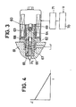
- a magnetic pressure control valve 60 is connected to port 40 of reaction force chamber 33.
- magnetic pressure control valve 60 is provided with a valve body 62 which is attached to housing 61, and a solenoid 63 that is secured to valve body 62.
- a spool member 64 which is adapted to be moved according to excitation of solenoid 63 is slidably accommodated in valve body 62.
- a valve seat member 66 which is secured to housing 61 is provided with a relief passage 65 that is connected to port 40 of the reaction device.
- a ball valve 67 which is engageable with valve seat member 66 to close relief passage 65 is urged toward valve seat member 66 by a spring 68 that is interposed between ball valve 67 and spool member 64.
- Spool member 64 is counterbalanced by a balance spring 69 and is usually maintained atthe position shown in FIGURE 3 where the force of spring 68 applied on ball valve 67 is maximum. The force of spring 68 will be reduced as spool member 64 is moved against balance spring 69 according to the excitation of solenoid 63.
- Solenoid 63 is connected to a solenoid drive circuit 71 which in turn is controlled by a computer 70. Current I which is supplied to solenoid 63 is controlled by computer 70 so as to decrease as the vehicle speed V increases.
- controlled pressure Pc in relief passage 65 namely, the pressure applied to the reaction device decreases, as shown in FIGURE 4.
- a magnetic throttle valve 60a which is operative to vary the area of a throttle according to current supplied to a solenoid thereof controls pressure Pc as a function of the current as shown in FIGURE 4, and may be substituted for magnetic flow control valve 60.
- Fluid flow discharged from pump 50 is divided into a first fluid flow of constant rate and an excess flow by first flow control valve 51.
- the first fluid flow is delivered to supply port 26 of servo-valve 20 to be distributed to the fluid motor.
- the excess flow is also divided into a second fluid flow of constant rate and an excess flow which is bypassed to the reservoir.
- the second fluid flow is delivered to port 40 of the reaction device and is led to the reservoir by way of magnetic pressure control valve 60. While the vehicle speed is low, the force of spring 68 is null because a maximum current I is supplied to solenoid 63.
- controlled pressure Pc namely, the pressure in the left chamber of reaction force chamber 33 is kept substantially null, and, in turn, reaction piston 35 is urged toward balls 36 only by the resilient force of wave spring 39.
- FIGURE 5 Another example of a reaction device is shown in FIGURE 5, wherein four reaction force cylinders 80 are radially formed at a cylindrical portion 81 of output shaft 11 at the same circumferentially interval.
- Four V-shaped grooves 82 are formed on an exterior surface of input shaft 24 opposite to reaction force cylinders 80.
- Plungers 83 which are slidably mounted in respective cylinders 80 include balls 85 which engage with grooves 82 respectively.
- An annular groove 86 is provided on an outer surface of cylinder portion 81 to communicate reaction force cylinders 80 with port 40 to which controlled pressure Pc is supplied.
- reaction force cylinders 33 or 80 are formed on a cylindrical portion of output shaft 11, the same effect as in the above-described embodiments can be obtained in the case where the reaction force cylinders are formed on a sleeve valve member.
- controlled pressure Pc supplied to the reaction device might be controlled according to another vehicle condition such as the rotational angle or rotational speed of the steering wheel or a desirable combination of selected vehicle conditions.
Landscapes
- Engineering & Computer Science (AREA)
- Chemical & Material Sciences (AREA)
- Combustion & Propulsion (AREA)
- Transportation (AREA)
- Mechanical Engineering (AREA)
- Steering Control In Accordance With Driving Conditions (AREA)
- Power Steering Mechanism (AREA)
Claims (5)
Applications Claiming Priority (2)
| Application Number | Priority Date | Filing Date | Title |
|---|---|---|---|
| JP59087221A JPH0645343B2 (ja) | 1984-04-27 | 1984-04-27 | 動力舵取装置の操舵力制御装置 |
| JP87221/84 | 1984-04-27 |
Publications (3)
| Publication Number | Publication Date |
|---|---|
| EP0159687A2 EP0159687A2 (fr) | 1985-10-30 |
| EP0159687A3 EP0159687A3 (en) | 1986-01-15 |
| EP0159687B1 true EP0159687B1 (fr) | 1990-01-24 |
Family
ID=13908840
Family Applications (1)
| Application Number | Title | Priority Date | Filing Date |
|---|---|---|---|
| EP85104874A Expired - Lifetime EP0159687B1 (fr) | 1984-04-27 | 1985-04-22 | Système de direction assistée |
Country Status (4)
| Country | Link |
|---|---|
| US (1) | US4593783A (fr) |
| EP (1) | EP0159687B1 (fr) |
| JP (1) | JPH0645343B2 (fr) |
| DE (1) | DE3575542D1 (fr) |
Cited By (2)
| Publication number | Priority date | Publication date | Assignee | Title |
|---|---|---|---|---|
| DE19633633A1 (de) * | 1996-08-21 | 1998-02-26 | Zahnradfabrik Friedrichshafen | Lenkventil für Hilfskraftlenkungen |
| DE19747639A1 (de) * | 1997-10-29 | 1999-05-06 | Zahnradfabrik Friedrichshafen | Drehschieberventil für Hilfskraftlenkungen von Kraftfahrzeugen |
Families Citing this family (14)
| Publication number | Priority date | Publication date | Assignee | Title |
|---|---|---|---|---|
| FR2575989B1 (fr) * | 1984-12-26 | 1989-08-04 | Nippon Seiko Kk | Dispositif de commande de force de direction pour systeme de direction assistee |
| JPS6259166A (ja) * | 1985-09-09 | 1987-03-14 | Koyo Seiko Co Ltd | 動力舵取装置に於ける操舵力制御装置 |
| JPS62152972A (ja) * | 1985-12-27 | 1987-07-07 | Toyoda Mach Works Ltd | 油圧反力式操舵力制御装置 |
| JPH0784180B2 (ja) * | 1986-01-16 | 1995-09-13 | 豊田工機株式会社 | 動力舵取装置の操舵力制御装置 |
| JPS62299478A (ja) * | 1986-06-19 | 1987-12-26 | Jidosha Kiki Co Ltd | 動力舵取装置の油圧反力装置 |
| WO1988001959A1 (fr) * | 1986-09-19 | 1988-03-24 | Zahnradfabrik Friedrichshafen Ag | Soupape de distribution rotative pour servo-directions hydrauliques |
| WO1988001958A1 (fr) * | 1986-09-19 | 1988-03-24 | Zahnradfabrik Friedrichshafen Ag | Soupape de distribution rotative pour servo-directions hydrauliques |
| DE3739848C2 (de) * | 1986-12-06 | 1996-09-05 | Zahnradfabrik Friedrichshafen | Drehschieberventil für hydraulische Hilfskraftlenkungen |
| US4819545A (en) * | 1987-07-28 | 1989-04-11 | Trw Inc. | Power steering system |
| JP2647094B2 (ja) * | 1987-07-30 | 1997-08-27 | 東芝機械株式会社 | リリーフ弁 |
| US5070958A (en) * | 1991-03-15 | 1991-12-10 | General Motors Corporation | Variable effort steering gear |
| JP3196415B2 (ja) * | 1993-03-29 | 2001-08-06 | 豊田工機株式会社 | 動力舵取装置用流量制御装置 |
| DE102005052078A1 (de) * | 2005-10-28 | 2007-05-16 | Thyssenkrupp Presta Steertec | Lenkeinrichtung mit Druckbegrenzungsventil zur Endlagendämpfung und Überlastschutz der Pumpe |
| KR100924566B1 (ko) | 2007-12-10 | 2009-10-30 | 영신정공 주식회사 | 차량용 오일 펌프의 압력 제어 밸브 |
Citations (1)
| Publication number | Priority date | Publication date | Assignee | Title |
|---|---|---|---|---|
| GB2035931A (en) * | 1978-11-30 | 1980-06-25 | Zahnradfabrik Friedrichshafen | Hydraulic steering system |
Family Cites Families (21)
| Publication number | Priority date | Publication date | Assignee | Title |
|---|---|---|---|---|
| US2791287A (en) * | 1954-07-19 | 1957-05-07 | Gen Motors Corp | Hydraulic power steering mechanism |
| US2893504A (en) * | 1954-12-30 | 1959-07-07 | Gen Motors Corp | Hydraulic steering system with control means for valve reaction pressures |
| GB821944A (en) * | 1955-12-06 | 1959-10-14 | Kent Ltd G | A new or improved control valve for power assisted steering mechanisms |
| US2939429A (en) * | 1957-10-21 | 1960-06-07 | Germane Corp | Rotary valve for power steering mechanism |
| BE609316A (fr) * | 1960-11-21 | 1962-02-15 | ||
| US3408900A (en) * | 1965-09-02 | 1968-11-05 | Toyoda Machine Works Ltd | Servo valve device in power steering gear of automobile |
| US3433127A (en) * | 1966-12-30 | 1969-03-18 | Gen Motors Corp | Power steering system with hydraulic reaction |
| US3406773A (en) * | 1967-10-27 | 1968-10-22 | Gen Motors Corp | Power steering gear |
| US3465842A (en) * | 1967-12-29 | 1969-09-09 | Bendix Corp | Power steering mechanism |
| US3690400A (en) * | 1970-06-01 | 1972-09-12 | Nissan Motor | Vehicle power steering control device |
| JPS4929653B1 (fr) * | 1970-08-06 | 1974-08-06 | ||
| JPS5345571B2 (fr) * | 1971-08-26 | 1978-12-07 | ||
| GB1432555A (en) * | 1972-09-08 | 1976-04-22 | Burman & Sons Ltd | Power-assisted steering gear |
| GB1465901A (en) * | 1973-02-01 | 1977-03-02 | Cam Gears Ltd | Power assisted vehicle steering |
| GB1597360A (en) * | 1976-12-16 | 1981-09-09 | Cam Gears Ltd | Powerassisted steering systems |
| JPS5814352B2 (ja) * | 1977-03-05 | 1983-03-18 | 自動車機器株式会社 | 動力舵取装置の操舵力制御装置 |
| US4189024A (en) * | 1978-06-23 | 1980-02-19 | Zahnradfabrik Friedrichshafen Ag | Auxiliary power steering for motor vehicles |
| DE2829064B2 (de) * | 1978-07-01 | 1981-02-12 | Zahnradfabrik Friedrichshafen Ag, 7990 Friedrichshafen | Hydraulische Hilfskraftlenkung für Kraftfahrzeuge |
| JPS5812866A (ja) * | 1981-07-13 | 1983-01-25 | Toyoda Mach Works Ltd | 動力舵取装置の操舵力制御装置 |
| IT1168203B (it) * | 1982-07-05 | 1987-05-20 | Daimler Benz Ag | Servosterzo per autoveicoli con valvola di modulazione per generare una pressione di reazione |
| US4485883A (en) * | 1982-09-30 | 1984-12-04 | Ford Motor Company | Power steering system with vehicle speed-sensitive flow |
-
1984
- 1984-04-27 JP JP59087221A patent/JPH0645343B2/ja not_active Expired - Lifetime
-
1985
- 1985-04-22 EP EP85104874A patent/EP0159687B1/fr not_active Expired - Lifetime
- 1985-04-22 DE DE8585104874T patent/DE3575542D1/de not_active Expired - Fee Related
- 1985-04-25 US US06/727,079 patent/US4593783A/en not_active Expired - Fee Related
Patent Citations (1)
| Publication number | Priority date | Publication date | Assignee | Title |
|---|---|---|---|---|
| GB2035931A (en) * | 1978-11-30 | 1980-06-25 | Zahnradfabrik Friedrichshafen | Hydraulic steering system |
Cited By (2)
| Publication number | Priority date | Publication date | Assignee | Title |
|---|---|---|---|---|
| DE19633633A1 (de) * | 1996-08-21 | 1998-02-26 | Zahnradfabrik Friedrichshafen | Lenkventil für Hilfskraftlenkungen |
| DE19747639A1 (de) * | 1997-10-29 | 1999-05-06 | Zahnradfabrik Friedrichshafen | Drehschieberventil für Hilfskraftlenkungen von Kraftfahrzeugen |
Also Published As
| Publication number | Publication date |
|---|---|
| JPH0645343B2 (ja) | 1994-06-15 |
| JPS60229870A (ja) | 1985-11-15 |
| DE3575542D1 (de) | 1990-03-01 |
| EP0159687A3 (en) | 1986-01-15 |
| US4593783A (en) | 1986-06-10 |
| EP0159687A2 (fr) | 1985-10-30 |
Similar Documents
| Publication | Publication Date | Title |
|---|---|---|
| EP0159687B1 (fr) | Système de direction assistée | |
| US4561521A (en) | Variable assist power steering system | |
| US4420934A (en) | Automotive vehicle hydraulic system | |
| US4676334A (en) | Power steering system with hydraulic reaction | |
| EP0106842B1 (fr) | Soupape de decharge pour pompe de direction assistee sensible a la vitesse | |
| US6041883A (en) | Flow controlling apparatus for power steering systems | |
| US4759420A (en) | Steering gear with speed sensitive detent switch | |
| US4715464A (en) | Power steering system with hydraulic reaction | |
| US4410058A (en) | Vehicle steering apparatus | |
| US5194053A (en) | Rotational speed differential responsive type control coupling with variable transfer torque control means | |
| US5184693A (en) | Vehicle hydraulic power steering system | |
| US4434866A (en) | Speed-sensitive power steering system | |
| US4877099A (en) | Electronically controlled variable assist power steering system | |
| EP0186135A2 (fr) | Appareil à force de réaction hydraulique pour système de direction assistée | |
| US4805714A (en) | Power steering system with hydraulic reaction | |
| US4418779A (en) | Control apparatus for vehicle steering system | |
| EP0653342A2 (fr) | Direction à assistance hydraulique | |
| US5357845A (en) | Power steering system | |
| EP0353458B1 (fr) | Système de contrôle de débit sensible à la pression et commandé électriquement | |
| CA1089323A (fr) | Regulateur de debit a deux etages pour servo- direction | |
| JPH0624959B2 (ja) | 動力舵取装置の操舵力制御装置 | |
| EP0721412B1 (fr) | Systeme de commande de fluide pour mecanisme de direction assistee de vehicule | |
| EP0405860B1 (fr) | Mécanisme de direction assistée | |
| JPH0747260Y2 (ja) | 動力舵取装置の操舵力制御装置 | |
| JPH036546Y2 (fr) |
Legal Events
| Date | Code | Title | Description |
|---|---|---|---|
| PUAI | Public reference made under article 153(3) epc to a published international application that has entered the european phase |
Free format text: ORIGINAL CODE: 0009012 |
|
| AK | Designated contracting states |
Designated state(s): DE FR GB |
|
| PUAL | Search report despatched |
Free format text: ORIGINAL CODE: 0009013 |
|
| AK | Designated contracting states |
Designated state(s): DE FR GB |
|
| 17P | Request for examination filed |
Effective date: 19860403 |
|
| 17Q | First examination report despatched |
Effective date: 19861120 |
|
| GRAA | (expected) grant |
Free format text: ORIGINAL CODE: 0009210 |
|
| AK | Designated contracting states |
Kind code of ref document: B1 Designated state(s): DE FR GB |
|
| REF | Corresponds to: |
Ref document number: 3575542 Country of ref document: DE Date of ref document: 19900301 |
|
| ET | Fr: translation filed | ||
| PLBE | No opposition filed within time limit |
Free format text: ORIGINAL CODE: 0009261 |
|
| STAA | Information on the status of an ep patent application or granted ep patent |
Free format text: STATUS: NO OPPOSITION FILED WITHIN TIME LIMIT |
|
| 26N | No opposition filed | ||
| PGFP | Annual fee paid to national office [announced via postgrant information from national office to epo] |
Ref country code: FR Payment date: 19920408 Year of fee payment: 8 |
|
| PGFP | Annual fee paid to national office [announced via postgrant information from national office to epo] |
Ref country code: GB Payment date: 19920410 Year of fee payment: 8 |
|
| PGFP | Annual fee paid to national office [announced via postgrant information from national office to epo] |
Ref country code: DE Payment date: 19920521 Year of fee payment: 8 |
|
| PG25 | Lapsed in a contracting state [announced via postgrant information from national office to epo] |
Ref country code: GB Effective date: 19930422 |
|
| GBPC | Gb: european patent ceased through non-payment of renewal fee |
Effective date: 19930422 |
|
| PG25 | Lapsed in a contracting state [announced via postgrant information from national office to epo] |
Ref country code: FR Effective date: 19931229 |
|
| PG25 | Lapsed in a contracting state [announced via postgrant information from national office to epo] |
Ref country code: DE Effective date: 19940101 |
|
| REG | Reference to a national code |
Ref country code: FR Ref legal event code: ST |