EP0159806A2 - Vorrichtung zum Kühlen von Metallbändern - Google Patents
Vorrichtung zum Kühlen von Metallbändern Download PDFInfo
- Publication number
- EP0159806A2 EP0159806A2 EP85301875A EP85301875A EP0159806A2 EP 0159806 A2 EP0159806 A2 EP 0159806A2 EP 85301875 A EP85301875 A EP 85301875A EP 85301875 A EP85301875 A EP 85301875A EP 0159806 A2 EP0159806 A2 EP 0159806A2
- Authority
- EP
- European Patent Office
- Prior art keywords
- temperature
- strip
- cooling
- coolant
- cooling roll
- Prior art date
- Legal status (The legal status is an assumption and is not a legal conclusion. Google has not performed a legal analysis and makes no representation as to the accuracy of the status listed.)
- Granted
Links
- 238000001816 cooling Methods 0.000 title claims abstract description 113
- 239000002184 metal Substances 0.000 title claims description 40
- 229910052751 metal Inorganic materials 0.000 title claims description 40
- 150000002739 metals Chemical class 0.000 title 1
- 239000002826 coolant Substances 0.000 claims abstract description 54
- 238000001514 detection method Methods 0.000 claims abstract description 8
- 230000001105 regulatory effect Effects 0.000 claims abstract description 7
- 238000010438 heat treatment Methods 0.000 claims description 4
- 239000012530 fluid Substances 0.000 claims description 3
- 238000004891 communication Methods 0.000 claims description 2
- 238000009835 boiling Methods 0.000 abstract description 4
- 238000000034 method Methods 0.000 description 11
- 238000002474 experimental method Methods 0.000 description 8
- XLYOFNOQVPJJNP-UHFFFAOYSA-N water Substances O XLYOFNOQVPJJNP-UHFFFAOYSA-N 0.000 description 8
- 239000000498 cooling water Substances 0.000 description 6
- 229910000831 Steel Inorganic materials 0.000 description 5
- 239000010959 steel Substances 0.000 description 5
- 230000008646 thermal stress Effects 0.000 description 4
- 238000000137 annealing Methods 0.000 description 3
- 230000005540 biological transmission Effects 0.000 description 3
- 230000003247 decreasing effect Effects 0.000 description 3
- 230000000694 effects Effects 0.000 description 3
- 239000000463 material Substances 0.000 description 3
- 150000003839 salts Chemical class 0.000 description 3
- 238000010276 construction Methods 0.000 description 2
- 230000001276 controlling effect Effects 0.000 description 2
- 238000011144 upstream manufacturing Methods 0.000 description 2
- 230000008878 coupling Effects 0.000 description 1
- 238000010168 coupling process Methods 0.000 description 1
- 238000005859 coupling reaction Methods 0.000 description 1
- 230000007423 decrease Effects 0.000 description 1
- 238000010586 diagram Methods 0.000 description 1
- 238000005246 galvanizing Methods 0.000 description 1
- 230000001788 irregular Effects 0.000 description 1
- 230000002093 peripheral effect Effects 0.000 description 1
- 230000035882 stress Effects 0.000 description 1
Images

Classifications
-
- F—MECHANICAL ENGINEERING; LIGHTING; HEATING; WEAPONS; BLASTING
- F28—HEAT EXCHANGE IN GENERAL
- F28F—DETAILS OF HEAT-EXCHANGE AND HEAT-TRANSFER APPARATUS, OF GENERAL APPLICATION
- F28F5/00—Elements specially adapted for movement
- F28F5/02—Rotary drums or rollers
-
- C—CHEMISTRY; METALLURGY
- C21—METALLURGY OF IRON
- C21D—MODIFYING THE PHYSICAL STRUCTURE OF FERROUS METALS; GENERAL DEVICES FOR HEAT TREATMENT OF FERROUS OR NON-FERROUS METALS OR ALLOYS; MAKING METAL MALLEABLE, e.g. BY DECARBURISATION OR TEMPERING
- C21D11/00—Process control or regulation for heat treatments
- C21D11/005—Process control or regulation for heat treatments for cooling
-
- C—CHEMISTRY; METALLURGY
- C21—METALLURGY OF IRON
- C21D—MODIFYING THE PHYSICAL STRUCTURE OF FERROUS METALS; GENERAL DEVICES FOR HEAT TREATMENT OF FERROUS OR NON-FERROUS METALS OR ALLOYS; MAKING METAL MALLEABLE, e.g. BY DECARBURISATION OR TEMPERING
- C21D9/00—Heat treatment, e.g. annealing, hardening, quenching or tempering, adapted for particular articles; Furnaces therefor
- C21D9/52—Heat treatment, e.g. annealing, hardening, quenching or tempering, adapted for particular articles; Furnaces therefor for wires; for strips ; for rods of unlimited length
- C21D9/54—Furnaces for treating strips or wire
- C21D9/56—Continuous furnaces for strip or wire
- C21D9/573—Continuous furnaces for strip or wire with cooling
-
- F—MECHANICAL ENGINEERING; LIGHTING; HEATING; WEAPONS; BLASTING
- F28—HEAT EXCHANGE IN GENERAL
- F28D—HEAT-EXCHANGE APPARATUS, NOT PROVIDED FOR IN ANOTHER SUBCLASS, IN WHICH THE HEAT-EXCHANGE MEDIA DO NOT COME INTO DIRECT CONTACT
- F28D21/00—Heat-exchange apparatus not covered by any of the groups F28D1/00 - F28D20/00
- F28D21/0001—Recuperative heat exchangers
-
- F—MECHANICAL ENGINEERING; LIGHTING; HEATING; WEAPONS; BLASTING
- F28—HEAT EXCHANGE IN GENERAL
- F28F—DETAILS OF HEAT-EXCHANGE AND HEAT-TRANSFER APPARATUS, OF GENERAL APPLICATION
- F28F27/00—Control arrangements or safety devices specially adapted for heat-exchange or heat-transfer apparatus
- F28F27/02—Control arrangements or safety devices specially adapted for heat-exchange or heat-transfer apparatus for controlling the distribution of heat-exchange media between different channels
-
- F—MECHANICAL ENGINEERING; LIGHTING; HEATING; WEAPONS; BLASTING
- F28—HEAT EXCHANGE IN GENERAL
- F28D—HEAT-EXCHANGE APPARATUS, NOT PROVIDED FOR IN ANOTHER SUBCLASS, IN WHICH THE HEAT-EXCHANGE MEDIA DO NOT COME INTO DIRECT CONTACT
- F28D21/00—Heat-exchange apparatus not covered by any of the groups F28D1/00 - F28D20/00
- F28D2021/0019—Other heat exchangers for particular applications; Heat exchange systems not otherwise provided for
- F28D2021/0077—Other heat exchangers for particular applications; Heat exchange systems not otherwise provided for for tempering, e.g. with cooling or heating circuits for temperature control of elements
Definitions
- the present invention relates to apparatus for cooling strip metal, for example, during passage of the strip through a continuous annealing Line, galvanizing Line, or the Like.
- FIG. 1(a) A typical known arrangement for the continuous cooling of strip metal processed in a continuous annealing furnace, or the like, is schematically shown in FIG. 1(a).
- strip metal 2 is fed around a plurality of spaced cooling rolls 1 so that the strip is cooled at the areas in contact with these cooling rolls, while passing therethrough.
- These cooling rolls 1 are, as typically shown in FIG. 1(b), of such a construction that they are rotatably supported on bearings 3, and have a helical or spiral passage 5 formed in the radially inner surface of a shell 4, around the outer surface of which the strip 2 passes in contact relationship.
- a pair of rotary coupling joints 6 are provided, adapted to inter-communicate with the mentioned spiral passage 5 via a rotating shaft 7, and through which cooling water is fed into the spiral passage 5 for cooling the shell 4.
- the number of cooling rolls 1 may vary depending upon the amount of cooling required of the strip.
- the range of control of the cooling rates attainable from such an arrangement would be substantially small, i.e. the volume of cooling water cannot be decreased significantly in view of the possibility that it will boil or vaporize, and with a change of water temperature say from 20 to 90°C, the control range attained at a strip temperature of around 800°C C could be as small as 10% or so; even with a strip temperature of 400°C, the control range would be merely 20% or so.
- the typical arrangement for cooling strip metal as discussed above is such that the angle of contact, and hence the area of contact between the strip and the cooling roll shells requires to be adjusted; this is effected in practice mostly from a change in the cooling roll positions.
- a change of cooling roll positions to achieve a required cooLing capacity is effected on every occasion that the material and thickness of strip and the running velocity of the strip cooling Line is changed, this could substantially affect the paraLLeL- ness between adjacent pairs of cooling rolls. This would then be not only a cause of mistracking or zig-zag running of the running strip, but also a further cause for unbalanced contact between the strip and the cooling rolls.
- the object of the present invention is to provide cooling apparatus which is adapted to prevent the occurrence of the irregularities and distortions in the configuration of strip metal without the need to change the angle of contact between the strip and cooling rolls.
- cooling apparatus for metal strip of the kind in which the strip is passed in contact partly around the outer circumferences of a number of spaced cooling rolls, through which coolant passes is characterized in that temperature detection means are provided for detecting the temperature of the strip metal before contact with each said cooling roll, in that coolant temperature adjusting means are provided which, in dependence upon the detected temperature, are adapted to adjust the temperature of the coolant passing through each cooling roll to a range which Limits the temperature drop such that unacceptable irregularities or distortions in the configuration of the strip cannot occur, and in that the coolant used for each cooling roll is selected with a boiling point appropriate to the respective detected temperature for each roll.
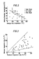
- FIG. 2 is a graph showing the results of a series of experiments conducted by the AppLicants as to the influence of the average temperature T of strip metal and the differential temperature T observed widthwise of the strip upon the possibility of configurational distortions of the strip occurring.
- marks 0, ⁇ and X are used, the mark 0 showing cases of good quality of configuration or shape of the strip, A showing cases of fair quality, and X showing the cases of poor quality.
- Cases of fair quality in configuration are considered here to mean strips having a degree of bowing or warping therein; cases of poor quality configuration are considered to mean strips having an appreciable waving or stretching, or even crumpling or wrinkling.
- the series of experiments were conducted on a plurality of steel strips having thicknesses ranging from 0.5 to 1.2mm and a width ranging from 800 to 1,200mm, stretched across a group of cooling rolls with tensions ranging from 0.5 through 3.0 kg/mm 2 . These steel strips were measured for their average temperatures T and their widthwise differential temperature AT after having passed through the cooling procedure, and their configurations were tested visually for any irregularities.
- this is a graph showing the relationship between maximum temperature drop TH and minimum temperature drop TL as observed widthwise of the strip metal in a further series of experiments conducted by the AppLicants . It can be seen from the graph that there exists a relationship between these two temperature drops as expressed by the following formula; i.e.,
- the graph confirms that there is the possibiLity of occurrence of difference of 1 : 5 in the rate of heat transmission as observed widthwise of the strip metal, due to a possible unevenness in contact of the strip with the cooling roLLs.
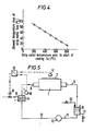
- FIG. 4 there is plotted the temperature of strip metal Ts1 prior to the start of the cooLing process on the abscissa axis, while the aLLowabLe extent of temperature drop of the strip Tsm is plotted on the ordinate axis.
- the allowable extent of the temperature drop Tsm where there is no improper configurational distortions of the strip may be expressed by the following equation; i.e.,
- AppLicants propose to have the value ⁇ Ts Limited in accordance with the following calculation as obtained from equation (3), as foLLows;
- the coolant passing through the interior passage of the cooling roll is preferably held with an as small as possible temperature change observed widthwise of the strip metal, in order to attain the effect of even cooling widthwise of the strip.
- the cooling process is designed with a relatively Large coolant flow rate so that the temperature rise of the coolant in the interior of the cooling roll may be held to be as small as possible in practice.
- the average temperature of the coolant Tw be taken to be equal to the coolant temperature at the entrance to the cooling roll Tw1.
- FIG. 5 there is shown a strip of metal 2 wrapped around the shell of a cooling roll 1 which is rotatably supported. Over the area of engagement in contact with the peripheral outer surface of the roll, the strip 2 is cooled off.
- the cooling roll 1 is provided as described hereinbefore, with a spiraL-shaped passage (not shown) around the inner surface of its shell, and coolant is introduced via a supply pipe 8 into the spiral passage. The coolant after abstracting heat from the strip 2 is discharged via a discharge pipe 9.
- the discharge pipe 9 is connected in communication with a storage tank 10 which is in turn connected with the cooling roll 1 through a supply pipe 11, a pump 12, a supply pipe 13, a heat exchanger 14 and the above mentioned supply pipe 8, in that order.
- coolant stored in the storage tank 10 is circulated through the cooling roll 1 by operation of the pump 12.
- the heat exchanger 14 comprises tubing 15 designed to receive cooling or heating fluid as appropriate, which fluid is regulated to an appropriate flow rate by a fLow rate regulating valve 16, whereby the temperature of the coolant can be properly adjusted.
- a temperature detector 17 is positioned and adapted to detect the temperature of the strip 2 prior to its contact with the cooling roll 1, and a further temperature detector 18 is positioned and adapted to detect the coolant temperature to be fed into the cooling roll 1.
- the output signals from these detectors are inputted to a control 19, by which the flow rate regulating valve 16 is regulated in accordance with these signals so that the coolant temperature may be properly adjusted. More specifically, it is arranged that the coolant temperature is adjusted on the basis of the temperature of the strip 2 prior to the start of the cooling operation as detected by the temperature detector 17, so that the coolant may be held at a temperature Tw1, as obtained from formula (7) above, that gives an allowed temperature drop Tsm which ensures that configurational distortions of the strip do not occur
- the storage tank 10 is provided with a coolant supply pipe 20 and a coolant discharge pipe 21 arranged in such a manner that the coolant passing through the cooling roLL 1 may be exchanged with another appropriate coolant, in accordance with the temperature of the strip 2 fed therethrough. More specifically, the kind of coolant may be selected as shown typically in TabLe 2, in accordance with the coolant temperature Tw1 as specified from the temperature Ts1 of the strip 2.
- the general Layout of the cooling Line comprises a series of cooling rolls 1,1',l" and 1"' for the sequential cooling operation of the strip metal, each having its own coolant circulating system R,R',R" and R"' respectively.
- this cooling system it is arranged that the strip of metal 2 is cooled-off in sequence as it passes in contact with each of the cooling rolls.
- the coolant fed into each of these cooling rolls is controlled at respective temperatures Tw1 in terms of a Limit value (as obtained from formula (7) above) on the basis of the temperature Ts1 of the strip metal 2, as detected by respective temperature detectors 17,17',17" and 17"' upstream of each of the cooling roLLs.
- the type of coolant is selected appropriately, in accordance with the specification shown in the TabLe 2, where the different types are defined in terms of the range of coolant temperature Tw1 required. More specifically, it can be seen that the appropriate coolant is selected to be molten salt, oil and water in the order of cooling steps from the upstream end of the strip metal 2, in terms of the required strip temperature, at each of the cooling steps. For example, it may be that molten salt is selected for the first cooling step provided by cooling roLL 1, oil for the next step (cooling roll 1') and water for the further steps (cooling roLL 1", 1"', respectively). Of course, it could happen that the same coolant may be used for two or more cooling steps, in which case the circulating system for the coolant may well be designed to be common for the corresponding cooling rolls, yet providing for independent temperature adjustment at the entrance to each such cooling roll.
- WhiLe coolants such as molten salt, oil and water as typical examples are proposed above in respect of the preferred embodiment, it is to be undertood that the present invention is not restricted to such coolants.
- the formulae adapted as discussed above to obtain the required coolant temperatures may Likewise be changed in accordance with the changes in conditions such as the kind of strip material, or the Like, as desire.
Landscapes
- Engineering & Computer Science (AREA)
- Chemical & Material Sciences (AREA)
- Physics & Mathematics (AREA)
- Thermal Sciences (AREA)
- Mechanical Engineering (AREA)
- General Engineering & Computer Science (AREA)
- Crystallography & Structural Chemistry (AREA)
- Materials Engineering (AREA)
- Metallurgy (AREA)
- Organic Chemistry (AREA)
- Heat Treatment Of Strip Materials And Filament Materials (AREA)
- Coating With Molten Metal (AREA)
Applications Claiming Priority (2)
| Application Number | Priority Date | Filing Date | Title |
|---|---|---|---|
| JP59075809A JPS60221533A (ja) | 1984-04-17 | 1984-04-17 | 金属ストリツプの冷却装置 |
| JP75809/84 | 1984-04-17 |
Publications (3)
| Publication Number | Publication Date |
|---|---|
| EP0159806A2 true EP0159806A2 (de) | 1985-10-30 |
| EP0159806A3 EP0159806A3 (en) | 1988-03-09 |
| EP0159806B1 EP0159806B1 (de) | 1991-04-24 |
Family
ID=13586885
Family Applications (1)
| Application Number | Title | Priority Date | Filing Date |
|---|---|---|---|
| EP85301875A Expired - Lifetime EP0159806B1 (de) | 1984-04-17 | 1985-03-18 | Vorrichtung zum Kühlen von Metallbändern |
Country Status (8)
| Country | Link |
|---|---|
| US (1) | US4638851A (de) |
| EP (1) | EP0159806B1 (de) |
| JP (1) | JPS60221533A (de) |
| KR (1) | KR900001092B1 (de) |
| CA (1) | CA1234977A (de) |
| DE (1) | DE3582609D1 (de) |
| ES (1) | ES8606508A1 (de) |
| ZA (1) | ZA852795B (de) |
Cited By (2)
| Publication number | Priority date | Publication date | Assignee | Title |
|---|---|---|---|---|
| EP1433036A4 (de) * | 2001-10-01 | 2008-10-22 | Entegris Inc | Vorrichtung zur konditionierung der temperatur eines fluids |
| EP1814678B2 (de) † | 2005-03-17 | 2014-08-27 | SMS Siemag AG | Verfahren und vorrichtung zum entzundern eines metallbandes |
Families Citing this family (7)
| Publication number | Priority date | Publication date | Assignee | Title |
|---|---|---|---|---|
| IT1189926B (it) * | 1986-02-18 | 1988-02-10 | Cefin Spa | Metodo per il raffreddamento del filo continuo di copertura di rulli di saldatura di una macchina per la saldatura in continuo di elementi tubolari |
| JPS62290832A (ja) * | 1986-06-11 | 1987-12-17 | Mitsubishi Heavy Ind Ltd | 金属ストリツプの加熱および冷却方法 |
| US5189960A (en) * | 1991-11-18 | 1993-03-02 | Fredric Valentini | Apparatus and method for controlling temperature of printing plate on cylinder in rotary press |
| US6662867B1 (en) * | 2000-10-30 | 2003-12-16 | Owens-Corning Fiberglas Technology, Inc. | Controlled heating of a coating material |
| ITUD20010101A1 (it) * | 2001-05-29 | 2002-11-29 | Danieli Off Mecc | Cristallizzatore a rulli per una macchina di colata continua |
| DE10137596A1 (de) * | 2001-08-01 | 2003-02-13 | Sms Demag Ag | Verfahren zur Kühlung von Werkstücken, insbesondere von Profilwalzprodukten, aus Schienenstählen |
| CN115537542B (zh) * | 2021-06-29 | 2026-03-17 | 宝山钢铁股份有限公司 | 采用冷却辊进行冷却的带钢冷却装置和方法 |
Family Cites Families (5)
| Publication number | Priority date | Publication date | Assignee | Title |
|---|---|---|---|---|
| US2890037A (en) * | 1954-11-10 | 1959-06-09 | United States Steel Corp | Method and apparatus for continuously cooling metal strips |
| US2971460A (en) * | 1959-03-30 | 1961-02-14 | George H Shindle | Method and apparatus for automatic temperature control of rotary printing press ink rollers |
| DE2055584A1 (de) * | 1970-11-12 | 1972-05-25 | Windmöller & Hölscher, 4540 Lengerich | Einrichtung zum Konstanthalten der Temperatur der Gegendruckzylinder von Mehrfarbendruckmaschinen |
| US4459726A (en) * | 1981-12-21 | 1984-07-17 | Usm Corporation | Temperature control for shell type rolls |
| JPS5920429A (ja) * | 1982-07-26 | 1984-02-02 | Nippon Kokan Kk <Nkk> | 連続焼鈍炉における鋼帯冷却方法 |
-
1984
- 1984-04-17 JP JP59075809A patent/JPS60221533A/ja active Pending
-
1985
- 1985-03-18 EP EP85301875A patent/EP0159806B1/de not_active Expired - Lifetime
- 1985-03-18 DE DE8585301875T patent/DE3582609D1/de not_active Expired - Lifetime
- 1985-04-11 US US06/722,213 patent/US4638851A/en not_active Expired - Lifetime
- 1985-04-15 ZA ZA852795A patent/ZA852795B/xx unknown
- 1985-04-16 CA CA000479265A patent/CA1234977A/en not_active Expired
- 1985-04-16 KR KR1019850002539A patent/KR900001092B1/ko not_active Expired
- 1985-04-16 ES ES542945A patent/ES8606508A1/es not_active Expired
Cited By (2)
| Publication number | Priority date | Publication date | Assignee | Title |
|---|---|---|---|---|
| EP1433036A4 (de) * | 2001-10-01 | 2008-10-22 | Entegris Inc | Vorrichtung zur konditionierung der temperatur eines fluids |
| EP1814678B2 (de) † | 2005-03-17 | 2014-08-27 | SMS Siemag AG | Verfahren und vorrichtung zum entzundern eines metallbandes |
Also Published As
| Publication number | Publication date |
|---|---|
| EP0159806A3 (en) | 1988-03-09 |
| US4638851A (en) | 1987-01-27 |
| EP0159806B1 (de) | 1991-04-24 |
| ES542945A0 (es) | 1986-04-16 |
| KR900001092B1 (ko) | 1990-02-26 |
| KR850007810A (ko) | 1985-12-09 |
| JPS60221533A (ja) | 1985-11-06 |
| ZA852795B (en) | 1985-12-24 |
| ES8606508A1 (es) | 1986-04-16 |
| CA1234977A (en) | 1988-04-12 |
| DE3582609D1 (de) | 1991-05-29 |
Similar Documents
| Publication | Publication Date | Title |
|---|---|---|
| EP0159806B1 (de) | Vorrichtung zum Kühlen von Metallbändern | |
| JPS6314050B2 (de) | ||
| JPS6230845B2 (de) | ||
| US3033539A (en) | Heat transfer apparatus for continuously moving strip | |
| AU614506B2 (en) | Method and system for suppressing fluctuation of width in hot rolled strip or sheet metal | |
| JPS5847457B2 (ja) | 連続焼鈍設備における鋼帯の冷却方法 | |
| KR890002799B1 (ko) | 연속 소둔로 냉각대의 스트립 온도 제어방법 | |
| JPS6020090B2 (ja) | 板材の冷却注水装置 | |
| EP0210847A2 (de) | Verfahren und Vorrichtung zur Abkühlung von Stahlbändern | |
| EP0108328A1 (de) | Vorrichtung zum kontinuierlichen Glühen | |
| JPS6013525Y2 (ja) | クラウン量可変ロ−ル | |
| JPS58128208A (ja) | 冷間圧延機のロ−ル冷却水供給方法及び装置 | |
| JPS6330371B2 (de) | ||
| JPS6340601B2 (de) | ||
| JPS5923826A (ja) | 冷却ロ−ルによる金属ストリツプ冷却方法 | |
| SU798056A1 (ru) | Вал дл прокатки стекла | |
| JPS6336042Y2 (de) | ||
| JPS6160901B2 (de) | ||
| JPS58100633A (ja) | クラウン可変水冷ロ−ル | |
| JPH051332A (ja) | 金属ストリツプのロール冷却装置 | |
| JP3114498B2 (ja) | 加熱炉の炉内ロールクラウン量調整方法 | |
| JPS59104436A (ja) | 金属ストリツプの冷却速度制御方法 | |
| JPH1190521A (ja) | 高温鋼板の冷却方法 | |
| JPH0361041B2 (de) | ||
| RU2191650C1 (ru) | Способ стабилизации теплового профиля валков |
Legal Events
| Date | Code | Title | Description |
|---|---|---|---|
| PUAI | Public reference made under article 153(3) epc to a published international application that has entered the european phase |
Free format text: ORIGINAL CODE: 0009012 |
|
| AK | Designated contracting states |
Designated state(s): DE FR GB |
|
| PUAL | Search report despatched |
Free format text: ORIGINAL CODE: 0009013 |
|
| AK | Designated contracting states |
Kind code of ref document: A3 Designated state(s): DE FR GB |
|
| 17P | Request for examination filed |
Effective date: 19880826 |
|
| 17Q | First examination report despatched |
Effective date: 19900213 |
|
| GRAA | (expected) grant |
Free format text: ORIGINAL CODE: 0009210 |
|
| AK | Designated contracting states |
Kind code of ref document: B1 Designated state(s): DE FR GB |
|
| REF | Corresponds to: |
Ref document number: 3582609 Country of ref document: DE Date of ref document: 19910529 |
|
| ET | Fr: translation filed | ||
| PLBE | No opposition filed within time limit |
Free format text: ORIGINAL CODE: 0009261 |
|
| STAA | Information on the status of an ep patent application or granted ep patent |
Free format text: STATUS: NO OPPOSITION FILED WITHIN TIME LIMIT |
|
| 26N | No opposition filed | ||
| REG | Reference to a national code |
Ref country code: GB Ref legal event code: IF02 |
|
| PGFP | Annual fee paid to national office [announced via postgrant information from national office to epo] |
Ref country code: FR Payment date: 20030310 Year of fee payment: 19 |
|
| PGFP | Annual fee paid to national office [announced via postgrant information from national office to epo] |
Ref country code: GB Payment date: 20030312 Year of fee payment: 19 |
|
| PGFP | Annual fee paid to national office [announced via postgrant information from national office to epo] |
Ref country code: DE Payment date: 20030327 Year of fee payment: 19 |
|
| PG25 | Lapsed in a contracting state [announced via postgrant information from national office to epo] |
Ref country code: GB Free format text: LAPSE BECAUSE OF NON-PAYMENT OF DUE FEES Effective date: 20040318 |
|
| PG25 | Lapsed in a contracting state [announced via postgrant information from national office to epo] |
Ref country code: DE Free format text: LAPSE BECAUSE OF NON-PAYMENT OF DUE FEES Effective date: 20041001 |
|
| GBPC | Gb: european patent ceased through non-payment of renewal fee |
Effective date: 20040318 |
|
| PG25 | Lapsed in a contracting state [announced via postgrant information from national office to epo] |
Ref country code: FR Free format text: LAPSE BECAUSE OF NON-PAYMENT OF DUE FEES Effective date: 20041130 |
|
| REG | Reference to a national code |
Ref country code: FR Ref legal event code: ST |