EP0159825A2 - Appareil de mesure de moment de torsion - Google Patents
Appareil de mesure de moment de torsion Download PDFInfo
- Publication number
- EP0159825A2 EP0159825A2 EP85302120A EP85302120A EP0159825A2 EP 0159825 A2 EP0159825 A2 EP 0159825A2 EP 85302120 A EP85302120 A EP 85302120A EP 85302120 A EP85302120 A EP 85302120A EP 0159825 A2 EP0159825 A2 EP 0159825A2
- Authority
- EP
- European Patent Office
- Prior art keywords
- sensing apparatus
- torque
- workpiece
- torque sensing
- bridge
- Prior art date
- Legal status (The legal status is an assumption and is not a legal conclusion. Google has not performed a legal analysis and makes no representation as to the accuracy of the status listed.)
- Withdrawn
Links
- 238000004804 winding Methods 0.000 claims abstract description 23
- 230000008878 coupling Effects 0.000 claims abstract description 5
- 238000010168 coupling process Methods 0.000 claims abstract description 5
- 238000005859 coupling reaction Methods 0.000 claims abstract description 5
- 230000015572 biosynthetic process Effects 0.000 abstract description 3
- 230000010363 phase shift Effects 0.000 abstract 2
- 239000011888 foil Substances 0.000 description 4
- 238000010586 diagram Methods 0.000 description 2
- 230000000694 effects Effects 0.000 description 2
- 230000035699 permeability Effects 0.000 description 2
- 230000035945 sensitivity Effects 0.000 description 2
- 230000004323 axial length Effects 0.000 description 1
- 238000005219 brazing Methods 0.000 description 1
- 239000012141 concentrate Substances 0.000 description 1
- 238000000034 method Methods 0.000 description 1
- 238000005476 soldering Methods 0.000 description 1
- 238000003466 welding Methods 0.000 description 1
- 229910000859 α-Fe Inorganic materials 0.000 description 1
Images


Classifications
-
- G—PHYSICS
- G01—MEASURING; TESTING
- G01L—MEASURING FORCE, STRESS, TORQUE, WORK, MECHANICAL POWER, MECHANICAL EFFICIENCY, OR FLUID PRESSURE
- G01L3/00—Measuring torque, work, mechanical power, or mechanical efficiency, in general
- G01L3/02—Rotary-transmission dynamometers
- G01L3/04—Rotary-transmission dynamometers wherein the torque-transmitting element comprises a torsionally-flexible shaft
- G01L3/10—Rotary-transmission dynamometers wherein the torque-transmitting element comprises a torsionally-flexible shaft involving electric or magnetic means for indicating
- G01L3/108—Rotary-transmission dynamometers wherein the torque-transmitting element comprises a torsionally-flexible shaft involving electric or magnetic means for indicating involving resistance strain gauges
-
- G—PHYSICS
- G01—MEASURING; TESTING
- G01L—MEASURING FORCE, STRESS, TORQUE, WORK, MECHANICAL POWER, MECHANICAL EFFICIENCY, OR FLUID PRESSURE
- G01L3/00—Measuring torque, work, mechanical power, or mechanical efficiency, in general
- G01L3/02—Rotary-transmission dynamometers
- G01L3/04—Rotary-transmission dynamometers wherein the torque-transmitting element comprises a torsionally-flexible shaft
- G01L3/10—Rotary-transmission dynamometers wherein the torque-transmitting element comprises a torsionally-flexible shaft involving electric or magnetic means for indicating
- G01L3/101—Rotary-transmission dynamometers wherein the torque-transmitting element comprises a torsionally-flexible shaft involving electric or magnetic means for indicating involving magnetic or electromagnetic means
- G01L3/105—Rotary-transmission dynamometers wherein the torque-transmitting element comprises a torsionally-flexible shaft involving electric or magnetic means for indicating involving magnetic or electromagnetic means involving inductive means
Definitions
- This invention relates to torque sensing apparatus.
- the torque on a shaft can be measured by using data fro; foil gauges adhered directly to the surface of the shaft or from a transducer partially inset into the shaft.
- Suitable transducers and mounting arrangements are described for example in British Patent No. 2,050,624B and in European Application Publication number 0127278, and a particular use on vehicle axles is described in European Application Publication number 0132930.
- torque sensing apparatus comprising a strain sensitive device with a bridge arrangement of gauges, characterised in that it is for a rotary workpiece and in that there are further provided transformers, each with one winding for rota ing with the workpiece and another winding fixed, means for feeding an oscillating signal to one fixed winding, means connecting the rotary windings to the bridge, and means for comparing the phase of the signal to said one fixed winding with the phase of the signal from the other fixed winding, the phase difference being indicative of torque.
- the transformers will preferably be axially spaced on opposite sides of the strain sensitive device.
- the windings may simply be turns coaxial with the workpiece,-and preferably they will be housed in annular channeled yokes which co-operate to enhance the magnetic coupling.
- the strain sensitive device will conveniently be mounted at anintermidiate point on a bridge member attached at axially spaced zones to the rotary workpiece, the bridge member being substantially more compliant than the rotary workpiece.
- the bridge member will be cylindrical and co-axially sleeve the workpiece with an annular gap intermediate the attachment zones. The response may be improved by cutting away part of the cylinder to form a central neck on which the strain sensitive device is mounted.
- torque sensing apparatus comprising means for attachment at axially spaced points to a workpiece subject to torque about its axis, a bridge member between, and spaced from the workpiece by, said attachment means, and a strain sensitive device at an intermediate point on the bridge member.
- foil gauges 1 may be adhered to the surface of a shaft 2 as shown at (a) in Figure 1.
- the gauges are in pairs lying in symmetrical formation on the lines of opposed helices of 45° pitch.
- An equivalent arrangement is shown at (b) in Figure 1, where a transducer 3 is inset into a shallow hole in the surface of the shaft 4, this transducer in effect incorporating four strain gauges in similar formation.
- gauges are also labelled as resistors Rl,R2,R3 and R4 for the purpose of Figure 2, which shows their connection, and also in Figure 6.
- R1 and R3 will change their resistance in one sense (for example reduce it) while - the other resistors R2 and-R4 will change in the opposite sense (increase in this example).
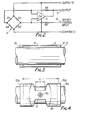
- They are arranged in a bridge circuit with a DC supply across one pair of opposed corners and the output taken from across the other pair. This is directed to an operational amplifier 5, to one input of which is also applied an offset control input 6.
- the output of the amplifier is to terminal 7 and there is also feedback to the other input via a resistor.
- the control input 6 may be adjusted to ensure that the output from terminal 7 at zero strain is equal to the desired zero reference level.
- FIG. 3 A possible solution to the mounting problem is shown in Figure 3 in which a shaft 8 is sleeved by a coaxial cylinder 9 having end rings 10 which are secured to the shaft 8 by welding, soldering or brazing, or by interference fit.
- the rings 10 are integral with the cylinder 9, but they may be separately constructed. They hold the cylinder so that there is a small annular gap between it and the shaft, and if the latter is subject to torque, so will the cylinder 9 be over the greater part of its axial length where it bridges the rings 10.
- a strain transducer disc 11 is inset centrally into it, with its component gauges oriented as described. These will produce data indicative of the torque on the cylinder 9, which will in turn be indicative of the torque on the shaft 8.
- the cylinder will stiffen the shaft locally between the rings 10, but not to any great extent since it is thin walled and considerably more compliant than the shaft itself.
- the cylinder may be cut away as shown in Figure 4. Similar parts are referenced as in Figure 3, but with the suffix a. This cutaway leaves the cylinder 9a with a neck 12 symmetrically between the rings 10a, and the transducer lla is central of this neck.
- the relative axial dimensions of the cylinder and its cutaway are indicated by L and 1 respectively. For any given torsional strain in the shaft, a larger torsional strain will be experienced by the transducer lla by a factor of approximately L/l, since in effect only the neck 12 will be compliant and the complete end portions of the cylinder will be substantially rigid.
- a shaft 13 extends through a stationary housing 14 and is fitted with a cutaway cylinder 15 similar to that of Figure 4.
- the neck is here referenced 16 and a strain gauge transducer 17 is fitted centrally to it.
- transformers 18 and 19 At the ends of the cylinder there are transformers 18 and 19, one winding 18a,19a of each being on the cylinder 15 and the others 18b,19b being on the housing 14.
- the windings are simply a plurality of turns co-axial with the shaft, and they are housed in annular, channeled yokes 20a,20b,21a,21b.
- the channels are open towards each other and they are of high magnetic permeability, such as ferrite,to provide efficient transformer coupling. Fine accuracy in their positioning and the winding operation is not necessary.
- the transducer 17 is wired to the windings 18a,19a as shown in Figure 6, one being the secondary of the transformer 18 and the other being the primary of the transformer 19.
- an oscillator 22 energises the primary 18b of the transformer 18, a transducer output is available from the secondary 19b of the transformer 19, whence it is directed through a high gain amplifier 23 to a phase sensitive detector 24 which also receives the oscillator output direct. From this and a low pass filter 25 there is produced a DC voltage which will be proportional to the torque in magnitude and size.
- the transformers are spaced apart on opposite sides of the transducer to reduce as far as possible any mutual interference.
- transformers may both be on the same side and well removed from the transducer. Also, although shown at the ends of the cylinder 15, overlying the attachment zones, the inner windings of the transformers may be mounted directly on the shaft.
Landscapes
- Physics & Mathematics (AREA)
- General Physics & Mathematics (AREA)
- Electromagnetism (AREA)
- Force Measurement Appropriate To Specific Purposes (AREA)
- Steering Controls (AREA)
- Arrangements For Transmission Of Measured Signals (AREA)
Applications Claiming Priority (2)
| Application Number | Priority Date | Filing Date | Title |
|---|---|---|---|
| GB8408502 | 1984-04-03 | ||
| GB848408502A GB8408502D0 (en) | 1984-04-03 | 1984-04-03 | Torque sensing apparatus |
Publications (2)
| Publication Number | Publication Date |
|---|---|
| EP0159825A2 true EP0159825A2 (fr) | 1985-10-30 |
| EP0159825A3 EP0159825A3 (fr) | 1987-04-15 |
Family
ID=10559065
Family Applications (1)
| Application Number | Title | Priority Date | Filing Date |
|---|---|---|---|
| EP85302120A Withdrawn EP0159825A3 (fr) | 1984-04-03 | 1985-03-27 | Appareil de mesure de moment de torsion |
Country Status (5)
| Country | Link |
|---|---|
| US (1) | US4649758A (fr) |
| EP (1) | EP0159825A3 (fr) |
| JP (1) | JPS615399A (fr) |
| AU (1) | AU4057385A (fr) |
| GB (1) | GB8408502D0 (fr) |
Cited By (10)
| Publication number | Priority date | Publication date | Assignee | Title |
|---|---|---|---|---|
| DE4009286A1 (de) * | 1990-03-22 | 1991-09-26 | Wiegand Gmbh & Co Alexander | Verfahren zum messen der torsion eines stabfoermigen koerpers sowie messelement zur durchfuehrung des verfahrens |
| EP0570066A1 (fr) * | 1992-05-09 | 1993-11-18 | Philips Patentverwaltung GmbH | Transducteur de contrainte pour mesurer le couple dans un arbre cylindrique |
| EP0740138A3 (fr) * | 1995-04-25 | 1997-05-21 | Werner & Pfleiderer | Dispositif de mesure du couple d'entrée d'une extrudeuse à plusieurs vis |
| DE19804695C1 (de) * | 1998-02-06 | 1999-06-24 | Staiger Mohilo & Co Gmbh | Anordnung zum Messen des Drehmoments von rotierenden Maschinenteilen mit Hilfe einer auf dem rotierenden Maschinenteil angebrachten Dehnungsmeßbrücke und schleifringloser Meßwertübertragung |
| DE10023961A1 (de) * | 2000-05-16 | 2002-01-31 | Sew Eurodrive Gmbh & Co | System zur Messung physikalischer Grössen bei einer Achse oder drehbaren Welle |
| WO2002023147A1 (fr) * | 2000-09-15 | 2002-03-21 | Robert Bosch Gmbh | Dispositif de mesure sans fil de l'effort exerce dans une tige mobile axialement |
| FR3014196A1 (fr) * | 2013-12-03 | 2015-06-05 | Snecma | Dispositif de montage de jauges de contraintes sur un arbre rotatif. |
| FR3017458A1 (fr) * | 2014-02-10 | 2015-08-14 | Snecma | Dispositif de mesure de couple pour arbre de turbomachine. |
| CN111033198A (zh) * | 2017-08-14 | 2020-04-17 | 阿自倍尓株式会社 | 扭矩检测器 |
| FR3090439A1 (fr) | 2018-12-21 | 2020-06-26 | Etablissements Georges Renault | outil électroportatif équipé d’un transformateur tournant doté de supports de bobine en plasto-ferrite |
Families Citing this family (12)
| Publication number | Priority date | Publication date | Assignee | Title |
|---|---|---|---|---|
| DE8700180U1 (de) * | 1987-01-03 | 1987-06-25 | Dietrich Grünau GmbH & Co KG, 7778 Markdorf | Meßwertübertrager |
| FR2707395B1 (fr) * | 1993-07-09 | 1995-10-06 | Facom | Outil de mesure d'un couple, tel qu'une clé dynamométrique électronique. |
| US6442812B1 (en) * | 2000-03-02 | 2002-09-03 | Eaton Corporation | Method of manufacturing a piezoelectric torque sensor |
| US20070241890A1 (en) * | 2006-03-31 | 2007-10-18 | Jun Yoshioka | Torque measurement system |
| CN100487403C (zh) * | 2007-10-01 | 2009-05-13 | 中北大学 | 张合式扭矩传感器 |
| JP6102004B2 (ja) * | 2012-01-31 | 2017-03-29 | ミネベアミツミ株式会社 | トルク変換器 |
| JP5710036B2 (ja) * | 2014-02-26 | 2015-04-30 | ユニパルス株式会社 | トルクセンサ |
| RU2555189C1 (ru) * | 2014-03-18 | 2015-07-10 | Закрытое акционерное общество "ИНСТРУМ-РЭНД" | Устройство для бесконтактного измерения крутящего момента |
| JP6843019B2 (ja) * | 2017-08-14 | 2021-03-17 | アズビル株式会社 | トルク検出器及びトルク検出器の製造方法 |
| JP6820102B2 (ja) * | 2017-08-14 | 2021-01-27 | アズビル株式会社 | トルク検出器及びトルク検出器の製造方法 |
| US11448562B2 (en) * | 2019-11-19 | 2022-09-20 | International Electronic Machines Corp. | Mechanical component torque measurement |
| EP4145099B1 (fr) | 2021-09-02 | 2025-06-11 | Ratier-Figeac SAS | Ensemble de mesure de contrainte |
Family Cites Families (12)
| Publication number | Priority date | Publication date | Assignee | Title |
|---|---|---|---|---|
| US2633019A (en) * | 1947-09-20 | 1953-03-31 | Glenn L Martin Co | Strain gauge pulse system |
| DE1115051B (de) * | 1957-03-30 | 1961-10-12 | Siemens Ag | Vorrichtung zur Ermittlung des in einer rotierenden Welle uebertragenen Drehmomentes |
| GB957653A (en) * | 1962-10-19 | 1964-05-06 | Ruston & Hornsby Ltd | Torque measuring apparatus |
| US3717029A (en) * | 1968-10-23 | 1973-02-20 | Himmelstein & Co S | Torquemeter |
| US3617878A (en) * | 1969-04-21 | 1971-11-02 | Blh Electronics | Ac to de high-accuracy low-level voltage measuring system |
| US3855857A (en) * | 1973-05-09 | 1974-12-24 | Schlumberger Technology Corp | Force-measuring apparatus for use in a well bore pipe string |
| GB2050624B (en) * | 1979-05-11 | 1983-08-03 | Barnett J D | Strain transducers |
| US4312241A (en) * | 1979-07-05 | 1982-01-26 | Productronix, Inc. | Load cell |
| US4545261A (en) * | 1983-03-21 | 1985-10-08 | International Harvester Company | Shaft torque measuring system |
| GB8308372D0 (en) * | 1983-03-26 | 1983-05-05 | Trw Probe Electronics Co Ltd | Strain transducers |
| GB2140565B (en) * | 1983-05-27 | 1986-11-12 | Asea Ab | Magnetoelastic torque transducer |
| GB8315346D0 (en) * | 1983-06-03 | 1983-07-06 | Trw Probe Electronics Co Ltd | Strain gauge assemblies |
-
1984
- 1984-04-03 GB GB848408502A patent/GB8408502D0/en active Pending
-
1985
- 1985-03-27 EP EP85302120A patent/EP0159825A3/fr not_active Withdrawn
- 1985-03-29 US US06/717,455 patent/US4649758A/en not_active Expired - Fee Related
- 1985-04-01 AU AU40573/85A patent/AU4057385A/en not_active Abandoned
- 1985-04-03 JP JP60070734A patent/JPS615399A/ja active Pending
Cited By (17)
| Publication number | Priority date | Publication date | Assignee | Title |
|---|---|---|---|---|
| DE4009286A1 (de) * | 1990-03-22 | 1991-09-26 | Wiegand Gmbh & Co Alexander | Verfahren zum messen der torsion eines stabfoermigen koerpers sowie messelement zur durchfuehrung des verfahrens |
| DE4009286C2 (de) * | 1990-03-22 | 2000-11-23 | Wiegand Gmbh & Co Alexander | Anordnung zum Messen der Torsion eines stabförmigen Hohlkörpers |
| EP0570066A1 (fr) * | 1992-05-09 | 1993-11-18 | Philips Patentverwaltung GmbH | Transducteur de contrainte pour mesurer le couple dans un arbre cylindrique |
| US5585572A (en) * | 1992-05-09 | 1996-12-17 | Kindler; Ulrich | Deformation measuring device for measuring the torque of a cylindrical shaft |
| EP0740138A3 (fr) * | 1995-04-25 | 1997-05-21 | Werner & Pfleiderer | Dispositif de mesure du couple d'entrée d'une extrudeuse à plusieurs vis |
| DE19804695C1 (de) * | 1998-02-06 | 1999-06-24 | Staiger Mohilo & Co Gmbh | Anordnung zum Messen des Drehmoments von rotierenden Maschinenteilen mit Hilfe einer auf dem rotierenden Maschinenteil angebrachten Dehnungsmeßbrücke und schleifringloser Meßwertübertragung |
| DE10023961A1 (de) * | 2000-05-16 | 2002-01-31 | Sew Eurodrive Gmbh & Co | System zur Messung physikalischer Grössen bei einer Achse oder drehbaren Welle |
| DE10023961B4 (de) * | 2000-05-16 | 2006-10-19 | Sew-Eurodrive Gmbh & Co. Kg | System zur Messung physikalischer Größen bei einer Achse oder drehbaren Welle |
| FR2814237A1 (fr) * | 2000-09-15 | 2002-03-22 | Bosch Gmbh Robert | Dispositif de mesure sans fil de l'effort exerce dans une tige mobile axialament |
| WO2002023147A1 (fr) * | 2000-09-15 | 2002-03-21 | Robert Bosch Gmbh | Dispositif de mesure sans fil de l'effort exerce dans une tige mobile axialement |
| FR3014196A1 (fr) * | 2013-12-03 | 2015-06-05 | Snecma | Dispositif de montage de jauges de contraintes sur un arbre rotatif. |
| FR3017458A1 (fr) * | 2014-02-10 | 2015-08-14 | Snecma | Dispositif de mesure de couple pour arbre de turbomachine. |
| CN111033198A (zh) * | 2017-08-14 | 2020-04-17 | 阿自倍尓株式会社 | 扭矩检测器 |
| CN111033198B (zh) * | 2017-08-14 | 2021-09-28 | 阿自倍尓株式会社 | 扭矩检测器 |
| FR3090439A1 (fr) | 2018-12-21 | 2020-06-26 | Etablissements Georges Renault | outil électroportatif équipé d’un transformateur tournant doté de supports de bobine en plasto-ferrite |
| EP3674036A1 (fr) | 2018-12-21 | 2020-07-01 | Etablissements Georges Renault | Outil électroportatif équipé d'un transformateur tournant doté de supports de bobine en plasto-ferrite |
| US11571791B2 (en) | 2018-12-21 | 2023-02-07 | Etablissements Georges Renault | Portable electrical tool equipped with a rotary transformer provided with coil having plasto-ferrite support |
Also Published As
| Publication number | Publication date |
|---|---|
| JPS615399A (ja) | 1986-01-11 |
| AU4057385A (en) | 1985-10-10 |
| GB8408502D0 (en) | 1984-05-16 |
| EP0159825A3 (fr) | 1987-04-15 |
| US4649758A (en) | 1987-03-17 |
Similar Documents
| Publication | Publication Date | Title |
|---|---|---|
| US4649758A (en) | Torque sensing apparatus | |
| KR900000660B1 (ko) | 비접촉 토오크 센서 | |
| JP4357841B2 (ja) | 磁気弾性トルクセンサー | |
| US4786846A (en) | Level guage apparatus | |
| US6443020B1 (en) | Steering column differential angle position sensor | |
| US6823746B2 (en) | Magnetoelastic torque sensor for mitigating non-axisymmetric inhomogeneities in emanating fields | |
| JPS5856082B2 (ja) | 誤配列検出装置 | |
| EP0367442B1 (fr) | Capteur de couple de rotation | |
| US4796463A (en) | Variable permeability steering torque sensor | |
| EP1752750B1 (fr) | Transducteur de couple magnéto-élastique | |
| EP1504246B1 (fr) | Ensemble de detection de courant de foucault permettant de mesurer le couple d'un arbre | |
| US3584505A (en) | Measuring device for monitoring stresses of a tool | |
| CA1229747A (fr) | Appareil d'analyse du couple | |
| EP0178780B1 (fr) | Monitoring du déplacement d'un accouplement de l'arbre | |
| JPS62108120A (ja) | トルクトランスジユ−サ | |
| JPS63188731A (ja) | 自動車の操舵トルク測定装置 | |
| JPH0512748Y2 (fr) | ||
| KR19980078163A (ko) | 차량용 조향장치의 토오크 센서 | |
| GB2140565A (en) | Magnetoelastic torque transducer | |
| JPS6161026A (ja) | 軸トルク計 | |
| KR200159423Y1 (ko) | 차량용 조향장치의 토오크 센서 | |
| SU1354028A1 (ru) | Измерительна цепь дл передачи информации с вращающихс изделий | |
| RU1809296C (ru) | Датчик угловых перемещений | |
| EP0279479B1 (fr) | Dispositif pour empêcher la surcharge pour des transducteurs de couple | |
| JPS63311136A (ja) | 磁歪式トルクセンサ |
Legal Events
| Date | Code | Title | Description |
|---|---|---|---|
| PUAI | Public reference made under article 153(3) epc to a published international application that has entered the european phase |
Free format text: ORIGINAL CODE: 0009012 |
|
| AK | Designated contracting states |
Designated state(s): DE FR GB IT SE |
|
| PUAL | Search report despatched |
Free format text: ORIGINAL CODE: 0009013 |
|
| AK | Designated contracting states |
Kind code of ref document: A3 Designated state(s): DE FR GB IT SE |
|
| 17P | Request for examination filed |
Effective date: 19871015 |
|
| STAA | Information on the status of an ep patent application or granted ep patent |
Free format text: STATUS: THE APPLICATION IS DEEMED TO BE WITHDRAWN |
|
| 18D | Application deemed to be withdrawn |
Effective date: 19881001 |
|
| RIN1 | Information on inventor provided before grant (corrected) |
Inventor name: HARBOUR, JOHN |