EP3674036A1 - Outil électroportatif équipé d'un transformateur tournant doté de supports de bobine en plasto-ferrite - Google Patents
Outil électroportatif équipé d'un transformateur tournant doté de supports de bobine en plasto-ferrite Download PDFInfo
- Publication number
- EP3674036A1 EP3674036A1 EP19214571.2A EP19214571A EP3674036A1 EP 3674036 A1 EP3674036 A1 EP 3674036A1 EP 19214571 A EP19214571 A EP 19214571A EP 3674036 A1 EP3674036 A1 EP 3674036A1
- Authority
- EP
- European Patent Office
- Prior art keywords
- winding
- ferrite
- tool according
- plasto
- rotor
- Prior art date
- Legal status (The legal status is an assumption and is not a legal conclusion. Google has not performed a legal analysis and makes no representation as to the accuracy of the status listed.)
- Granted
Links
Images


Classifications
-
- B—PERFORMING OPERATIONS; TRANSPORTING
- B25—HAND TOOLS; PORTABLE POWER-DRIVEN TOOLS; MANIPULATORS
- B25B—TOOLS OR BENCH DEVICES NOT OTHERWISE PROVIDED FOR, FOR FASTENING, CONNECTING, DISENGAGING, OR HOLDING
- B25B23/00—Details of, or accessories for, spanners, wrenches, screwdrivers
- B25B23/14—Arrangement of torque limiters or torque indicators in wrenches or screwdrivers
- B25B23/147—Arrangement of torque limiters or torque indicators in wrenches or screwdrivers specially adapted for electrically operated wrenches or screwdrivers
- B25B23/1475—Arrangement of torque limiters or torque indicators in wrenches or screwdrivers specially adapted for electrically operated wrenches or screwdrivers for impact wrenches or screwdrivers
-
- H—ELECTRICITY
- H01—ELECTRIC ELEMENTS
- H01F—MAGNETS; INDUCTANCES; TRANSFORMERS; SELECTION OF MATERIALS FOR THEIR MAGNETIC PROPERTIES
- H01F38/00—Adaptations of transformers or inductances for specific applications or functions
- H01F38/18—Rotary transformers
-
- H—ELECTRICITY
- H02—GENERATION; CONVERSION OR DISTRIBUTION OF ELECTRIC POWER
- H02K—DYNAMO-ELECTRIC MACHINES
- H02K11/00—Structural association of dynamo-electric machines with electric components or with devices for shielding, monitoring or protection
- H02K11/20—Structural association of dynamo-electric machines with electric components or with devices for shielding, monitoring or protection for measuring, monitoring, testing, protecting or switching
- H02K11/24—Devices for sensing torque, or actuated thereby
-
- H—ELECTRICITY
- H02—GENERATION; CONVERSION OR DISTRIBUTION OF ELECTRIC POWER
- H02K—DYNAMO-ELECTRIC MACHINES
- H02K7/00—Arrangements for handling mechanical energy structurally associated with dynamo-electric machines, e.g. structural association with mechanical driving motors or auxiliary dynamo-electric machines
- H02K7/14—Structural association with mechanical loads, e.g. with hand-held machine tools or fans
- H02K7/145—Hand-held machine tool
-
- G—PHYSICS
- G11—INFORMATION STORAGE
- G11B—INFORMATION STORAGE BASED ON RELATIVE MOVEMENT BETWEEN RECORD CARRIER AND TRANSDUCER
- G11B5/00—Recording by magnetisation or demagnetisation of a record carrier; Reproducing by magnetic means; Record carriers therefor
- G11B5/62—Record carriers characterised by the selection of the material
- G11B5/68—Record carriers characterised by the selection of the material comprising one or more layers of magnetisable material homogeneously mixed with a bonding agent
- G11B5/70—Record carriers characterised by the selection of the material comprising one or more layers of magnetisable material homogeneously mixed with a bonding agent on a base layer
- G11B5/706—Record carriers characterised by the selection of the material comprising one or more layers of magnetisable material homogeneously mixed with a bonding agent on a base layer characterised by the composition of the magnetic material
- G11B5/70626—Record carriers characterised by the selection of the material comprising one or more layers of magnetisable material homogeneously mixed with a bonding agent on a base layer characterised by the composition of the magnetic material containing non-metallic substances
- G11B5/70642—Record carriers characterised by the selection of the material comprising one or more layers of magnetisable material homogeneously mixed with a bonding agent on a base layer characterised by the composition of the magnetic material containing non-metallic substances iron oxides
- G11B5/70678—Ferrites
-
- H—ELECTRICITY
- H01—ELECTRIC ELEMENTS
- H01F—MAGNETS; INDUCTANCES; TRANSFORMERS; SELECTION OF MATERIALS FOR THEIR MAGNETIC PROPERTIES
- H01F1/00—Magnets or magnetic bodies characterised by the magnetic materials therefor; Selection of materials for their magnetic properties
- H01F1/01—Magnets or magnetic bodies characterised by the magnetic materials therefor; Selection of materials for their magnetic properties of inorganic materials
- H01F1/03—Magnets or magnetic bodies characterised by the magnetic materials therefor; Selection of materials for their magnetic properties of inorganic materials characterised by their coercivity
- H01F1/032—Magnets or magnetic bodies characterised by the magnetic materials therefor; Selection of materials for their magnetic properties of inorganic materials characterised by their coercivity of hard-magnetic materials
- H01F1/10—Magnets or magnetic bodies characterised by the magnetic materials therefor; Selection of materials for their magnetic properties of inorganic materials characterised by their coercivity of hard-magnetic materials non-metallic substances, e.g. ferrites, e.g. [(Ba,Sr)O(Fe2O3)6] ferrites with hexagonal structure
- H01F1/11—Magnets or magnetic bodies characterised by the magnetic materials therefor; Selection of materials for their magnetic properties of inorganic materials characterised by their coercivity of hard-magnetic materials non-metallic substances, e.g. ferrites, e.g. [(Ba,Sr)O(Fe2O3)6] ferrites with hexagonal structure in the form of particles
-
- H—ELECTRICITY
- H02—GENERATION; CONVERSION OR DISTRIBUTION OF ELECTRIC POWER
- H02K—DYNAMO-ELECTRIC MACHINES
- H02K7/00—Arrangements for handling mechanical energy structurally associated with dynamo-electric machines, e.g. structural association with mechanical driving motors or auxiliary dynamo-electric machines
- H02K7/003—Couplings; Details of shafts
Definitions
- the field of the invention is that of the design and manufacture of electromechanical tools used in industry and which can be a screwdriver, a drill or a torque measurement device. More specifically, the invention relates to a rotary transformer on board the rotor of an electromechanical tool and designed to generate an electrical voltage intended to supply an electronic card placed on the rotor.
- the supports of the coils contained in the rotary transformer according to the invention are made of plasto-ferrite to give them increased impact resistance.
- electromechanical tools are used in industry, on automobile production lines for example. These tools are for example: screwdrivers, impact or impulse wrenches, drills, torque measuring devices, and generally any tool with a rotating shaft and extending at one end by a member terminal, a screwdriver bit for example.
- This type of tool is subject to severe conditions of use: high productivity and shocks due to not very careful handling or to poorly damped docking in the context of an automatic machine or even vibrations specific to screwdrivers with discontinuous tightening.
- the strain gauges are glued to the rotary shaft in the form of a Wheastone bridge, it is not possible to supply them and recover their signal with simple wires making the electrical junction between the rotating shaft and the electronic card of the tool.
- solutions using a rotary transformer have been developed to make the electrical connection between the tool housing and the shaft.
- a rotary transformer offers good durability, which is not the case for an electrical collector whose brushes are subject to wear.
- Screwdrivers generally integrate a torque measurement on the shaft.
- the transformer provides electrical power by induction to the board on the rotary shaft.
- This rotary transformer typically comprises two rings, one for the stator and the other for the rotor, these rings being made of ferrite.
- Ferrite powders are composed of iron oxide (manganese, nickel).
- the magnetic properties of ferrite powders are obtained by a heat treatment. This method of production is analogous to the manufacture of ferrite where the ferrite powder provided with its binder is compacted before passing through the furnace.
- the function of the on-board electronic card consists in recovering a supply voltage coming from the rotor and transmitting it to the gauges after rectification then in recovering the output voltage of the gauges, conditioning it and transmitting it to the rotor.
- a main electronic card is carried by the casing and works in a complementary manner with the card on the output shaft.
- the invention particularly aims to provide an effective solution to at least some of these different problems.
- an objective of the invention is to provide a solution for strengthening the impact resistance of the element making it possible to measure the torque applied to the rotary shaft of an electromechanical tool.
- Another objective of the invention is to set up a technique for producing a transformer which uses standard, reliable and robust means, but which are also simple to design. This technique must also make it possible to reduce the production costs of the transformer.
- the invention provides an electromechanical tool comprising a casing, a shaft animating in rotation a tip, and a rotary transformer.
- the rotary shaft incorporates an electronic circuit intended to measure a physical quantity of the shaft
- the rotary transformer comprises a stator secured to the casing and a rotor fixed to the rotary shaft.
- the stator integrates a first winding and a first support of this first winding
- the rotor integrates a second winding and a second support of this second winding.
- the supports are made of plasto-ferrite material.
- the tool thus produced is more solid and more resistant to shocks, in particular to falls.
- the physical quantity measured is a torque or a force.
- the tool is informed about the torque or the force which is applied to the moving parts, more particularly the torque applied to a screw or the tensile force installed in a screw following a screwing.
- the plasto-ferrite material consists of different metals reduced to powder and of a plastic matrix binding the grains of metal.
- the matrix is chosen from the following list of materials: polyamide, polyacetal. phenylene polysulfide.
- the ferrite concentration is between 80% and 95% of the total mass of the plasto-ferrite material.
- the diameter of the wires surrounding said coils is between 0.25 and 0.35 millimeters.
- the ferrite powder is non-magnetic.
- the ferrite powder is chosen from a powder list comprising: (alloy of Iron, Nickel, Zinc, Aluminum and Silicon), (alloy of Iron and Sodium).
- the magnetic permeability of the plasto-ferrite is between 5 and 30.
- the ratio of the number of turns of the stator to that of the rotor is between 0.2 and 0.5.
- a power tool for example, fitted with a torque sensor on the rotary shaft.
- the present invention is based on the use of a material called plasto-ferrite combining a plastic or resin matrix loaded with ferrite powder.
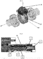
- the Fig. 1 presents an example of an electromechanical tool according to an exemplary embodiment of the invention.
- the tool is a screwing device, or screwdriver 1.
- a screwdriver comprises a casing 2 housing inside the motor means which in this embodiment comprise an electric motor.
- the screwdriver comprises an output shaft 3 which has a first end 5 which extends outside the casing 2. This first end is intended to cooperate with a terminal element which is for example a screwdriver bit or a socket intended to cooperate with an element to screw.
- the output shaft 3 has a second end 6 which is directly connected to the motor shaft or to a reduction means, the latter being connected to the motor shaft.
- the screwdriver comprises control means in the form of a main electronic card 4 which make it possible to control the screwdriver.
- the transmission and in particular the reduction may be such that the output shaft 3 extends perpendicular to the axis of the drive means.
- This screwdriver incorporates a main electronic card which supports the means of control of the screwdriver.
- This main electronic card in particular receives signals from a torque sensor to determine the tightening torque from the measurement of the deformations of the output shaft 3 by means of the gauges. Part 20 of the tool is shown in the Fig. 5 .
- the rotary transformer supplies the on-board card with an electrical voltage produced by the main card of the screwdriver and which, once rectified by the on-board card, supplies the bridge with strain gauges.
- This gauge bridge produces an output signal in the form of a voltage which is transformed into a digital signal by the on-board circuit to then be recovered via the rotary transformer and returned to the main electronic card.
- the frequency of the alternating voltage signal supplying the coil 9 which emits the electromagnetic field is typically between 100 Khz and 200 Khz. Communication is typically carried out at a rate of between 1 Mbits and 2 Mbits per second.
- the matrix can also consist of phenylene polysulfide.
- these plasto-ferrites have a concentration of much lower ferrite than a conventional sintered component whose ferrite proportion is greater than 95% for a permeability of: ⁇ > 100).
- the energy transformation yield is optimal for a ferrite concentration of between 80% and 95% of the total mass of the plasto-ferrite material.
- This value of magnetic permeability is given without unit in fact, it is the multiplication of this value by the magnetic permeability of the vacuum ⁇ 0 (which it is in Henry per meter [H / m]). The result gives the magnetic permeability of the materials.
- the low ferrite content greatly alters the magnetic permeability ( ⁇ varying from 5 to 30). This deficiency is compensated for by a specific winding described later in the description. Furthermore, a low remanence of the transformer is sought so as to maximize the efficiency of the transformer. For this reason, it is necessary to minimize another variable which is the coercive field, that must be between 50 and 1000 A / m
- the transformer traversed by a magnetic field retains its magnetic property unchanged.
- the hysteresis effect as shown in Fig. 2 illustrates this principle.
- the x axis indicates the strength of the magnetic field H and the y axis, the degree of magnetization B.
- This figure clearly shows that the relationship between the field strength (H) and the magnetization (B) n is not linear.
- the initial magnetization curve increases rapidly at the start, then becomes asymptotic when reaching the point of magnetic saturation (Hs).
- Hs point of magnetic saturation
- B the phenomenon of hysteresis.
- the magnetization is shifted from the origin by a value equal to the afterglow.
- there is no magnetic field there is also no (at the beginning) magnetization and the curves are confused from the start.
- the Fig. 3 represents the section of a rotating transformer seen from the front and side view according to an exemplary embodiment.
- the rotary transformer comprises a coil 10 inside the stator 11, and a second coil 12 around the rotor 13.
- the rotary transformer comprises in particular two cores which can be of multiple shapes and placed facing each other. opposite (here in the example illustrated by these two figures: two concentric rings). These two cores are each provided with a coil.
- Each winding sometimes primary, sometimes secondary, generates or collects a magnetic field channeled by the plasto-ferrite cores.
- the section view shown in the Fig. 3 allows you to view the geometry of the magnetic cores and the arrangement of the two windings 10 and 12 facing each other.
- Each coil is made up of enameled wires of a section and a number of turns of specific wires.
- the size of the rings is calculated by the theory of magnetism and simulation.
- plasto-ferrite unlike a more efficient pure ferrite material, the flux density generated is low because of the low coupling ratio.
- the inductance affects by its value the capacity to transmit with the same winding a power signal and a high frequency transmission signal.
- the width of the ranges is chosen so as to satisfy the dual use of the transformer: supply of the electronic card on board the output shaft at a frequency between 100 Khz and 200 Khz and transmission of the signal from the digitized gauge bridge ( conditioned) at high frequency.
- the inductance is dependent on the properties of the core (magnetic permeability, the geometry of the core, the value of the air gap and the characteristics of the coil (number of turns and section of the wire).
- the second stage consists in prototyping and testing because the simulation does not allow an easy assessment of the losses linked to the transformer environment (steel shaft and casing, permeable cover) which degrade the coupling ratios.
- the size of the winding wire is increased within the limit of the size and the minimum inductance criterion.
- the minimum inductance constrains a minimum number of turns.
- the optimization criterion was to reduce losses by increasing the section of the coil wires within the limit of reducing the number of turns.
- the wire diameter initially from 0.11 to 0.15 millimeters is increased to reach a value between 0.25 and 0.35 millimeters.
- the other means of optimization is the use of "taps" which make it possible to specialize the winding according to the mode of use, power supply or data transmission.
- the tapping consists in providing electrical connections between the two ends of the coils allowing a configuration of double winding on the rotor and the stator used according to the functional mode (power supply or high frequency communication).
- This branching allows, in power generation mode for the supply of the secondary circuit, to configure a maximum number of turns.
- This connection also allows, in high frequency communication mode, to increase the communication capacity by reducing the number of turns.
- the Fig. 4 shows a perspective view of the coupling between the rotor and the stator according to another embodiment of a rotary transformer.
- the rotor part 17 remains unchanged with the principle of an O-ring provided with a coil produced by a winding of traditional wire.
- the stator part 16 adopts a “C” shape whose opening allows the passage of the rotor part 17.
- the core of the stator part occupies a prismatic volume which makes it possible to locate the form in a portion of revolution around the tool axis.
- the compactness of the solution is degraded locally in a sector but makes it possible to provide maximum compactness of the solution outside this sector.
- the Fig. 5 shows a sectional view of the part referenced 20 of the tool presented on the Fig. 1 showing the rotor and stator of a rotating transformer according to an exemplary embodiment.
- the output shaft 3 supports an electronic card 12 also driven in rotation. This card is connected to strain gauges measuring the torque.
- the devices proposed comprise different variants, modifications and improvements which will be obvious to those skilled in the art, it being understood that these different variants, modifications and improvements make part of the scope of the invention, as defined by the claims which follow.
- different aspects and characteristics described above can be implemented together, or separately, or else substituted for one another, and all of the different combinations and sub combinations of aspects and characteristics are part of the scope of the 'invention.
- some devices described above may not incorporate all of the modules and functions provided for the embodiments described.
Landscapes
- Engineering & Computer Science (AREA)
- Power Engineering (AREA)
- Mechanical Engineering (AREA)
- Microelectronics & Electronic Packaging (AREA)
- Force Measurement Appropriate To Specific Purposes (AREA)
- Coils Or Transformers For Communication (AREA)
- Arrangements For Transmission Of Measured Signals (AREA)
- Recording Or Reproducing By Magnetic Means (AREA)
Abstract
Description
- Le domaine de l'invention est celui de la conception et de la fabrication d'outils électromécaniques utilisés dans l'industrie et pouvant être une visseuse, une perceuse ou un dispositif de mesure du couple. Plus précisément, l'invention concerne un transformateur tournant embarqué sur le rotor d'un outil électromécanique et conçus pour générer une tension électrique destinée à alimenter une carte électronique placée sur le rotor. Les supports des bobines contenues dans le transformateur tournant selon l'invention sont fabriqués en plasto-ferrite pour leur conférer une résistance au choc accrue.
- De nombreux outils électromécaniques sont utilisés dans l'industrie, sur des chaînes de fabrication automobile par exemple. Ces outils sont par exemple : des visseuses, des clés à choc ou à impulsions, des perceuses, des dispositifs de mesure de couple, et de façon générale tout outil doté d'un arbre animé en rotation et se prolongeant à une extrémité par un organe terminal, un embout de vissage par exemple. Ce type d'outil est soumis à des conditions d'utilisation sévères : forte productivité et chocs dus à des manipulations peu précautionneuses ou à des accostages peu amortis dans le cadre de machine automatique ou encore des vibrations propres à des visseuses à serrage discontinu.
- Ces outils peuvent disposer d'un moyen de mesure du couple appliqué sur l'arbre de sortie rotatif. Il s'avère que la mesure de couple dans ces outils électromécanique procure de meilleurs résultats si elle est appliquée au plus près de l'organe terminal et donc sur l'arbre de sortie de la visseuse. Des capteurs de couple dits dynamiques ont été développés à cet effet.
- Dans ce type de structure, les jauges de contrainte sont collées sur l'arbre rotatif sous la forme d'un pont de Wheastone, il n'est pas possible de les alimenter et de récupérer leur signal avec de simples fils faisant la jonction électrique entre l'arbre tournant et la carte électronique de l'outil. Pour répondre à cette difficulté, des solutions utilisant un transformateur tournant, ont été développées pour réaliser la connexion électrique entre le carter de l'outil et l'arbre. Un transformateur tournant offre une bonne durabilité, ce qui n'est pas le cas d'un collecteur électrique dont les balais sont soumis à de l'usure. Les visseuses intègrent généralement une mesure de couple sur l'arbre.
- Un outil rotatif utilisant des moyens inductifs sans contacts mécaniques pour assurer l'alimentation et la communication avec les moyens de mesure du couple qui sont embarqués sur l'arbre, comporte notamment les éléments suivants :
- un carter formant l'enveloppe extérieure de l'outil,
- une carte électronique principale supportant les moyens de contrôle de la visseuse,
- des éléments d'interface permettant le support mécanique de la visseuse durant son fonctionnement ainsi que son activation et l'affichage de son statut,
- des moyens moteur, intégrant éventuellement un moteur électrique synchrone à aimant permanent animant en rotation un arbre de sortie,
- des moyens de mesure du couple intégrant :
- une carte électronique embarquée sur l'arbre de sortie.
- un pont de jauge de contraintes collé sur l'arbre de sortie
- un transformateur tournant comportant un stator fixe par rapport au carter et un rotor fixe par rapport à l'arbre et situé en vis-à-vis du stator, le stator étant relié à la carte électronique principale et le rotor étant relié à la carte embarquée.
- Le transformateur assure l'alimentation électrique par induction de la carte embarquée sur l'arbre rotatif. Ce transformateur tournant comporte typiquement deux bagues, l'une pour le stator et l'autre pour le rotor, ces bagues étant réalisées en ferrite. Les poudres de ferrite sont composées d'oxyde de fer (manganèse, nickel). Les propriétés magnétiques des poudres de ferrites sont obtenues par un traitement thermique. Ce mode d'obtention est analogue à la fabrication de ferrite où la poudre de ferrite munie de son liant est compactée avant passage au four.
- La fonction de la carte électronique embarquée consiste à récupérer une tension d'alimentation venant du rotor et de la transmettre aux jauges après redressement puis à récupérer la tension de sortie des jauges, la conditionner et la transmettre au rotor. Une carte électronique principale est portée par le carter et fonctionne de façon complémentaire avec la carte embarquée sur l'arbre de sortie.
- Le brevet
EP0712105 "Electrical power and signal transmission system", déposé le 14/11/1994 décrit une telle solution. Ce type de structure utilise un transformateur tournant dont les bagues sont réalisées en ferrite pour satisfaire à une circulation correcte du champ magnétique. Ces composants sont composés de deux bobines disposées sur un support capable de canaliser le flux magnétique. Ce support est réalisé en ferrite et mis en œuvre par frittage. Ce matériau procure une performance particulière au transformateur tournant caractérisé par sa perméabilité magnétique. Les surfaces des bagues en vis-à-vis sont dimensionnées pour permettre la transmission du flux magnétique d'une bague à l'autre au travers de l'entrefer. - D'autres documents de l'état de la technique décrivent en partie ou totalité ce type de dispositif, qui sont cités ci-après au titre d'arrière-plan technologique :
- le document
DE 1920890 déposé le 03/04/1980 illustre un exemple de transformateur tournant. - le document
EP0159825 déposé le 15/06/1984 illustre un capteur de couple utilisant des transformateurs tournants. - le document
JPS614676 - le document
DE4210201 déposé le 28/03/1992 illustre une visseuse pneumatique munie d'un capteur de couple à jauges de contraintes sur l'arbre de sortie, l'alimentation et la récupération du signal des jauges de contraintes étant réalisées par 1 transformateur tournant. Une électronique de traitement du signal est embarquée sur l'arbre tournant pour conditionner le signal avant de le renvoyer vers les moyens de contrôle de l'outil par le même transformateur tournant. - le document
DE4307131 déposé le 06/03/1993 illustre une mesure de couple sur un arbre de sortie de visseuse, l'alimentation et la récupération du signal des jauges de contraintes étant réalisées par 1 transformateur tournant. - le document
DE19637934 déposé le 1/09/1996 illustre des moyens de mesure de couple sur l'arbre de sortie d'une visseuse d'angle. Un transformateur tournant est utilisé pour alimenter les jauges de contraintes sur l'arbre tournant. Le signal produit par ces jauges est renvoyé vers les moyens de contrôle de l'outil grâce à des moyens optique. - le document
JP2010184329 - le document
WO2007063106 déposé le 01/05/2005 illustre une visseuse d'angle comportant des moyens de mesure de couple sur son arbre de sortie. Un transformateur tournant est utilisé pour alimenter et récupérer le signal d'un pont de jauges collées sur l'arbre. - le document
WO2010144048 déposé le 11/06/2009 illustre une visseuse comportant des moyens de mesure de couple sur un arbre tournant. Un transformateur tournant est utilisé pour alimenter et récupérer le signal d'un pont de jauges collées sur l'arbre. Les éléments en ferrite sont fragiles et risque de se fendre et de casser sous le choc, par exemple lors de la chute de l'outil sur le sol. La réparation d'un tel outil est fastidieuse car elle nécessite un démontage complet de l'arbre rotatif. - La réalisation d'un transformateur tournant par frittage de poudre de ferrite impose un procédé de frittage spécifique à chaque géométrie et ne permet pas l'emploi d'une méthode d'usinage standard.
- L'invention a notamment pour objectif d'apporter une solution efficace à au moins certains de ces différents problèmes.
- En particulier, selon au moins un mode de réalisation, un objectif de l'invention est de fournir une solution pour renforcer la résistance aux chocs de l'élément permettant de mesurer le couple appliqué à l'arbre rotatif d'un outil électromécanique.
- Un autre objectif de l'invention est de mettre en place une technique de réalisation d'un transformateur qui utilise des moyens standards, fiables et robustes, mais également simples de conception. Cette technique doit également permettre de diminuer les coûts de production du transformateur.
- Pour ceci, l'invention propose un outil électromécanique comportant un carter, un arbre animant en rotation un embout, et un transformateur tournant. L'arbre rotatif intégre un circuit électronique destiné à mesurer une grandeur physique de l'arbre, et le transformateur tournant comporte un stator solidarisé avec le carter et un rotor fixé à l'arbre rotatif. Le stator intégre un premier bobinage et un premier support de ce premier bobinage, le rotor intégre un deuxième bobinage et un deuxième support de ce deuxième bobinage. Les supports sont réalisés en matériau plasto-ferrite.
- De cette manière, l'outil ainsi réalisé est plus solide et résiste mieux aux chocs, en particulier aux chutes.
- Selon un premier mode de réalisation, la grandeur physique mesurée est un couple ou une force. De cette façon, l'outil est renseigné sur le couple ou la force qui s'applique sur les pièces en mouvement, plus particulièrement le couple appliqué sur une vis ou la force de traction installée dans une vis à la suite d'un vissage.
- Selon un autre mode de réalisation, le matériau plasto-ferrite est constitué de différents métaux réduits en poudre et d'une matrice plastique liant les grains de métal.
- Selon un autre mode de réalisation, la matrice est choisie dans la liste de matériaux suivants : polyamide, polyacétale. polysulfure de phénylène.
- Selon un autre mode de réalisation, la concentration en ferrite est comprise entre 80 % et 95 % de la masse totale du matériau plasto-ferrite.
- Selon un autre mode de réalisation, le diamètre des fils entourant lesdits bobinages se situe entre 0.25 et 0.35 millimètres.
- Selon un autre mode de réalisation, la poudre de ferrite est amagnétique.
- Selon un autre mode de réalisation, la poudre de ferrite est choisie dans une liste de poudre comprenant: (alliage de Fer, Nickel, Zinc, Aluminium et Silicium), (alliage de Fer et Sodium).
- Selon un autre mode de réalisation, la perméabilité magnétique de la plasto-ferrite est comprise entre 5 et 30.
- Selon un autre mode de réalisation, le rapport du nombre de spires du stator sur celui du rotor est compris entre 0,2 et 0,5.
- D'autres caractéristiques et avantages de l'invention apparaîtront à la lecture de la description suivante de modes de réalisation particuliers, donnée à titre de simple exemple illustratif et non limitatif, et des dessins annexés parmi lesquels :
- [
Fig 1 ] : lafigure 1 illustre un schéma d'un outil électromécanique mettant en œuvre l'invention ; - [
Fig 2 ] : lafigure 2 illustre une courbe d'hystérésis représentant la relation entre la force de champ H et l'aimantation B ; - [
Fig 3 ] : lafigure 3 représente la section d'un transformateur tournant vue de face et vue de coté selon un exemple de réalisation ; - [
Fig 4 ] : lafigure 4 montre une vue en perspective du couplage entre le rotor et le stator selon un autre mode de réalisation d'un transformateur tournant ; - [
Fig 5 ] : lafigure 5 montre une vue en coupe d'un outil montrant le rotor et le stator d'un transformateur tournant selon un exemple de réalisation. - On présente en relation avec les
figures 1 ,3 à 6 un outil électroportatif, une visseuse par exemple, doté d'un capteur de couple embarqué sur l'arbre rotatif. La présente invention repose sur l'usage d'un matériau nommé plasto-ferrite alliant une matrice en plastique ou résine chargée avec de la poudre de ferrite. - La
Fig. 1 présente un exemple d'outil électromécanique selon un exemple de réalisation de l'invention. Selon cet exemple, l'outil est un dispositif de vissage, ou visseuse 1. Ainsi que cela est représenté sur laFig.1 , une telle visseuse comprend un carter 2 logeant à l'intérieur des moyens moteurs qui dans ce mode de réalisation comprennent un moteur électrique. La visseuse comprend un arbre de sortie 3 qui présente une première extrémité 5 qui s'étend en dehors du carter 2. Cette première extrémité est destinée à coopérer avec un élément terminal qui est par exemple un embout de vissage ou une douille prévue pour coopérer avec un élément à visser. L'arbre de sortie 3 présente une deuxième extrémité 6 qui est directement reliée à l'arbre du moteur ou à un moyen de réduction, ce dernier étant relié à l'arbre du moteur. - La visseuse comprend des moyens de contrôle sous la forme d'une carte électronique principale 4 qui permettent de piloter la visseuse.
- Selon une variante de réalisation, la transmission et notamment la réduction pourront être telles que l'arbre de sortie 3 s'étend perpendiculairement à l'axe des moyens moteur.
- Cette visseuse intègre une carte électronique principale qui supporte les moyens de contrôle de la visseuse. Cette carte électronique principale reçoit notamment des signaux provenant d'un capteur de couple pour déterminer le couple de serrage à partir de la mesure des déformations de l'arbre de sortie 3 au moyen des jauges. La partie 20 de l'outil est représenté sur la
Fig. 5 . - Cette visseuse représenté en entier par le
Fig. 1 intègre également un capteur de couple. Ce capteur se présente sous la forme d'un module traversé par l'arbre de sortie de la visseuse. Il intègre : - un transformateur tournant 7,
- un arbre sur lequel est collé un pont de jauges de contraintes 8,
- une carte électronique embarquée dans un alésage coaxial à l'arbre 9.
- Le transformateur tournant fournit à la carte embarquée une tension électrique produite par la carte principale de la visseuse et qui, une fois redressée par la carte embarquée, alimente le pont de jauges de contraintes. Ce pont de jauge produit un signal de sortie sous la forme d'une tension qui est transformée en signal numérique par le circuit embarqué pour ensuite être récupéré via le transformateur tournant et renvoyé vers la carte électronique principale. La fréquence du signal de tension alternatif alimentant le bobinage 9 qui émet le champ électromagnétique est typiquement compris entre 100 Khz et 200 Khz. La communication s'effectue typiquement à un débit compris entre 1 Mbits et 2 Mbits par seconde.
- La présente invention repose sur l'usage d'un matériau nommé plasto-ferrite alliant une matrice en plastique ou résine chargée avec de la poudre de ferrite pour la réalisation de bagues du transformateur tournant. Voici deux exemples de matières proposées pour réaliser les bagues constituant le transformateur tournant :
- une première matière comportant une matrice en polyamide et comme métal : du Fer, du Nickel et du Zinc, ainsi que de l'Aluminium et du Silicium en proportion moindre.
- une seconde matière comportant une matrice en polyacétal (P.O.M. en abrégé) et comme métal du Fer, et du Sodium en faible proportion.
- Selon un alternative au polyamide et polyacétal, la matrice peut être également constituée de polysulfure de phénylène.
- On peut noter que ces plasto-ferrites disposent d'une concentration en ferrite bien plus faible qu'un composant conventionnel fritté dont la proportion en ferrite est supérieure à 95% pour une perméabilité de : µ >100). L'expérimentation a montré que le rendement de la transformation énergétique est optimal pour une concentration en ferrite comprise entre 80 % et 95 % de la masse totale du matériau plasto-ferrite. Cette valeur de perméabilité magnétique est donnée sans unité en fait, c'est la multiplication de cette valeur par la perméabilité magnétique du vide µ0 (qui elle est en Henry par mètre [H/m]). Le résultat donne la perméabilité magnétique du matériaux.
- Pour une proportion de 82%, on obtient une perméabilité électromagnétique de µ=8, et pour une proportion de 89 %, on obtient : µ=14.
- La faible teneur en ferrite altère grandement la perméabilité magnétique (µ variant de 5 à 30). Cette déficience est compensée par un bobinage spécifique décrit plus loin dans la description. Par ailleurs, une rémanence faible du transformateur est recherchée de manière à maximiser le rendement du transformateur. Pour cette raison, il est nécessaire de minimiser une autre variable qui est le champ coercitif, celui doit être compris entre 50 et 1000 A/m
- De cette manière, le transformateur parcouru par un champ magnétique (nécessaire au principe de transmission de flux du primaire au secondaire) conserve sa propriété magnétique inchangée.
- L'effet d'hystérésis tel que montré à la
Fig.2 illustre ce principe. Sur cette figure, l'axe x indique la force du champ magnétique H et l'axe y, le degré de magnétisation B. Cette figure montre bien que la relation entre la force du champ (H) et l'aimantation (B) n'est pas linéaire. Ainsi, si le matériau est démagnétisé (H = B = 0), alors la courbe d'aimantation initiale augmente rapidement au début, puis devient asymptotique en atteignant le point de saturation magnétique (Hs). Si, par la suite, le champ magnétique est réduit de manière monotone, alors B suit une courbe différente, d'où le phénomène d'hystérésis. Lorsque le champ devient nul, l'aimantation est décalée de l'origine d'une valeur égale à la rémanence. Lorsqu'il n'y a pas de champ magnétique, il n'y a pas non plus (au début) de magnétisation et les courbes sont confondues dès l'origine. - La
Fig. 3 représente la section d'un transformateur tournant vue de face et vue de coté selon un exemple de réalisation. - Le transformateur tournant comporte un bobinage 10 à l'intérieur du stator 11, et un second bobinage 12 autour du rotor 13. Comme le montre ces deux figures, le transformateur tournant comporte notamment deux noyaux qui peuvent être de formes multiples et placés en vis-à-vis (ici dans l'exemple illustré par ces deux figures : deux bagues concentriques). Ces deux noyaux sont munis chacun d'un bobinage. Chaque bobinage tantôt primaire, tantôt secondaire, génère ou recueille un champ magnétique canalisé par les noyaux en plasto-ferrite.
- La vue en section montrée à la
Fig. 3 permet de visualiser la géométrie des noyaux magnétiques et la disposition des deux bobinages 10 et 12 en vis-à-vis. Chaque bobine est composée de fils émaillés d'une section et d'un nombre de tours de fils spécifiques. - Ces représentations montre les deux noyaux magnétiques 14 et 15 servant de support aux bobinages, ces noyaux formant deux anneaux l'un interne et l'autre externe. L'ensemble des caractéristiques des deux bobinages 10 et 12 et des deux noyaux 14 et 15 de plasto-ferrite définissent les propriétés intrinsèques du transformateur tournant dans sa capacité à transmettre le flux magnétique souhaité.
- Le dimensionnement des bagues est calculé par la théorie du magnétisme et simulation. Avec la plasto-ferrite à la différence d'un matériau de ferrite pur plus performant, la densité de flux généré est faible à cause du faible rapport de couplage.
- L'inductance affecte par sa valeur la capacité à transmettre avec un même bobinage un signal de puissance et un signal de transmission haute fréquence.[1]
- La première étape du dimensionnement du transformateur tournant consiste en une simulation numérique afin de calculer :
- les flux magnétiques induits,
- le rapport de couplage entre le stator et le rotor dans les deux sens qui doit être maximal et le plus proche de 1,
- l'inductance du stator doit être comprise de préférence entre 5 et 20 µH suivant la taille du transformateur,
- l'inductance du rotor doit être comprise de préférence entre 40 et 200 µH suivant la taille du transformateur.
- La largeur des plages est choisie de façon à satisfaire à la double utilisation du transformateur : alimentation de la carte électronique embarquée sur l'arbre de sortie à une fréquence comprise entre 100 Khz et 200 Khz et la transmission du signal du pont de jauges numérisé (conditionné) à haute fréquence.
- L'inductance est dépendante des propriétés du noyau (perméabilité magnétique, de la géométrie du noyau, de la valeur de l'entrefer et des caractéristiques de la bobine (nombre de spires et section du fil).
- La deuxième étape consiste à prototyper et tester car la simulation ne permet pas d'évaluer aisément les pertes liées à l'environnement du transformateur (arbre et carter en acier, capotage perméable) qui dégradent les rapports de couplage.
- Pour compenser le faible rapport de couplage, résultant de la faible densité en ferrite, il faut augmenter le courant sans amplifier démesurément les pertes en joules. Pour cela, la taille du fil de bobinage est augmentée dans la limite de l'encombrement et du critère d'inductance minimal.
- Enfin, l'inductance minimale contraint un nombre minimal de spires.
- L'ensemble de ces critères constitue les variables dépendantes du système.
- Pour permettre la fonctionnalité du transformateur tournant avec ce matériau particulier, l'expérimentation a conduit à concevoir un bobinage qui minimise les pertes en joule et augmente le rapport de couplage. Le critère d'optimisation a été de réduire les pertes par augmentation de la section des fils de bobines dans la limite de la réduction du nombre de spires.
- Pour compenser la faible valeur de µ, le diamètre des fils initialement de 0.11 à 0.15 millimètres est augmenté pour atteindre une valeur entre 0.25 et 0.35 millimètres.
- L'autre moyen d'optimisation est le recours à des « piquages » qui permettent de spécialiser le bobinage en fonction du mode d'utilisation, alimentation ou transmission de données.
- Le piquage consiste à prévoir des connexions électriques entre les deux extrémités des bobines permettant une configuration de bobinage double sur le rotor et le stator utilisé selon le mode fonctionnel (alimentation de puissance ou communication haute fréquence). Ce piquage permet, en mode de génération de puissance pour l'alimentation du circuit secondaire, de configurer un nombre maximum de spires. Ce piquage permet aussi, en mode de communication haute fréquence, d'augmenter la capacité de communication par réduction du nombre de spire.
- La
Fig. 4 montre une vue en perspective du couplage entre le rotor et le stator selon un autre mode de réalisation d'un transformateur tournant. - Afin de répondre à une contrainte de compacité du produit une architecture de transformateur particulière est apportée. La partie rotor 17 reste inchangée avec le principe d'une bague torique munie d'une bobine réalisée par un enroulement de fil traditionnel. La partie stator 16 par contre adopte une forme en «C» dont l'ouverture permet le passage de la partie rotor 17. Le noyau de la partie stator occupe un volume prismatique qui permet de localiser la forme dans une portion de révolution autour de l'axe de l'outil. La compacité de la solution est dégradée localement sur un secteur mais permet d'apporter une compacité maximale de la solution hors de ce secteur.
- Avec une architecture de la sorte le couplage sur un secteur limité affecte la densité de flux magnétique.
- La
Fig. 5 montre une vue en coupe de la partie référencée 20 de l'outil présenté sur laFig. 1 montrant le rotor et le stator d'un transformateur tournant selon un exemple de réalisation. L'arbre de sortie 3 supporte une carte électronique 12 animé également en rotation. Cette carte est reliée à des jauges de contraintes mesurant le couple. - Bien que décrits à travers un certain nombre d'exemples de réalisation détaillés, les dispositifs proposés comprennent différentes variantes, modifications et perfectionnements qui apparaîtront de façon évidente à l'homme de l'art, étant entendu que ces différentes variantes, modifications et perfectionnements font partie de la portée de l'invention, telle que définie par les revendications qui suivent. De plus, différents aspects et caractéristiques décrits ci-dessus peuvent être mis en œuvre ensemble, ou séparément, ou bien substitués les uns aux autres, et l'ensemble des différentes combinaisons et sous combinaisons des aspects et caractéristiques font partie de la portée de l'invention. En outre, il se peut que certains dispositifs décrits ci-dessus n'incorporent pas la totalité des modules et fonctions prévus pour les modes de réalisation décrits.
Claims (10)
- Outil électromécanique (1), tel qu'une visseuse une perceuse ou un dispositif de mesure de couple, comportant un carter (2), un arbre (3) animant en rotation un embout, et un transformateur tournant (10, 11, 12, 13, 14, 15) ledit arbre rotatif intégrant un circuit électronique destiné à mesurer une grandeur physique de l'arbre, ledit transformateur tournant comportant un stator (11) solidarisé avec le carter et un rotor (13) fixé à l'arbre rotatif, le stator intégrant un premier bobinage (10) et un premier support dudit premier bobinage, le rotor intégrant un deuxième bobinage (12) et un deuxième support dudit deuxième bobinage, caractérisé en ce que lesdits supports sont réalisés en matériau plasto-ferrite.
- Outil selon la revendication 1 dans lequel la grandeur physique mesurée est un couple ou une force.
- Outil selon la revendication 1 ou 2 dans lequel le matériau plasto-ferrite est constitué de différents métaux réduits en poudre et d'une matrice plastique liant les grains de métal.
- Outil selon la revendication 3, caractérisé en ce que la matrice est choisie dans la liste de matériaux suivants : polyamide, polyacétale. polysulfure de phénylène.
- Outil selon la revendication 3 ou 4, caractérisé en ce que la concentration en ferrite est comprise entre 80 % et 95 % de la masse totale du matériau plasto-ferrite.
- Outil selon l'une quelconque des revendications précédentes, caractérisé en ce que le diamètre des fils entourant lesdits bobinages se situe entre 0.25 et 0.35 millimètres.
- Outil selon l'une quelconque des revendications précédentes, caractérisé en ce la poudre de ferrite est amagnétique.
- Outil selon l'une quelconque des revendications précédentes, caractérisé en que la poudre de ferrite est choisie dans une liste de poudre comprenant : (alliage de Fer, Nickel, Zinc, Aluminium et Silicium), (alliage de Fer et Sodium).
- Outil selon l'une quelconque des revendications précédentes, caractérisé en ce que la perméabilité magnétique de la plasto-ferrite est comprise entre 5 et 30.
- Outil selon l'une quelconque des revendications précédentes, caractérisé en ce que le rapport du nombre de spires du premier bobinage (10) du stator (11) sur le nombre de spires du second bobinage (12) du rotor (13) est compris entre 0,2 et 0,5.
Applications Claiming Priority (1)
| Application Number | Priority Date | Filing Date | Title |
|---|---|---|---|
| FR1873880A FR3090439B1 (fr) | 2018-12-21 | 2018-12-21 | outil électroportatif équipé d’un transformateur tournant doté de supports de bobine en plasto-ferrite |
Publications (2)
| Publication Number | Publication Date |
|---|---|
| EP3674036A1 true EP3674036A1 (fr) | 2020-07-01 |
| EP3674036B1 EP3674036B1 (fr) | 2022-08-31 |
Family
ID=66776489
Family Applications (1)
| Application Number | Title | Priority Date | Filing Date |
|---|---|---|---|
| EP19214571.2A Active EP3674036B1 (fr) | 2018-12-21 | 2019-12-09 | Outil électroportatif équipé d'un transformateur tournant doté de supports de bobine en plasto-ferrite |
Country Status (3)
| Country | Link |
|---|---|
| US (1) | US11571791B2 (fr) |
| EP (1) | EP3674036B1 (fr) |
| FR (1) | FR3090439B1 (fr) |
Families Citing this family (2)
| Publication number | Priority date | Publication date | Assignee | Title |
|---|---|---|---|---|
| US20230124788A1 (en) * | 2019-10-10 | 2023-04-20 | Gary William Box | Rotary Transformer |
| WO2022243010A1 (fr) * | 2021-05-17 | 2022-11-24 | Atlas Copco Industrial Technique Ab | Outil électrique avec capacité de transfert de signal sans fil |
Citations (12)
| Publication number | Priority date | Publication date | Assignee | Title |
|---|---|---|---|---|
| DE1920890A1 (de) | 1969-04-24 | 1970-11-12 | Guenther Vogeler | Schleifringloser induktiver UEbertrager |
| EP0159825A2 (fr) | 1984-04-03 | 1985-10-30 | TRW Transportation Electronics Limited | Appareil de mesure de moment de torsion |
| JPS614676A (ja) | 1984-06-15 | 1986-01-10 | ヨコタ工業株式会社 | インパルスレンチの締付トルク制御装置 |
| DE4210201A1 (de) | 1992-03-28 | 1993-09-30 | Gardner Denver Gmbh | Schrauber, insbesondere Druckluftschrauber |
| DE4307131A1 (de) | 1993-03-06 | 1994-09-08 | Albert Kipfelsberger | Kraftschrauber mit elektronischer Drehmomentbegrenzung |
| EP0712105A2 (fr) | 1994-11-14 | 1996-05-15 | Clyde L. Ruthroff | Système de transmission d'énergie et de signaux électriques |
| DE19637934A1 (de) | 1996-09-17 | 1998-03-26 | Psm Drucklufttechnik Vertrieb | Winkelschrauber mit eingebautem Drehmomentgeber |
| FR2839825A1 (fr) * | 2002-05-17 | 2003-11-21 | Seb Sa | Moteur electrique pour appareil electromenager de preparation culinaire |
| WO2007063106A1 (fr) | 2005-12-01 | 2007-06-07 | Etablissements Georges Renault | Outil de vissage a tete d'angle, incluant un capteur de couple monte sur l'arbre de sortie, et module de transmission correspondant |
| JP2010184329A (ja) | 2009-02-13 | 2010-08-26 | Hitachi Koki Co Ltd | 動力工具 |
| WO2010144048A1 (fr) | 2009-06-11 | 2010-12-16 | Atlas Copco Tools Ab | Clé à choc portative pourvue d'un boîtier d'engrenage et d'un dispositif de détection de paramètre |
| EP3043458A1 (fr) * | 2014-12-31 | 2016-07-13 | Société Électromécanique du Nivernais | Moteur electrique tubulaire |
Family Cites Families (10)
| Publication number | Priority date | Publication date | Assignee | Title |
|---|---|---|---|---|
| DE4214376A1 (de) * | 1992-04-30 | 1993-11-04 | Siemens Matsushita Components | Magnetisches material fuer leistungsuebertragerkerne |
| JP3418827B2 (ja) * | 2000-03-15 | 2003-06-23 | ミネベア株式会社 | Mn−Znフェライトおよびその製造方法 |
| JPWO2006126298A1 (ja) * | 2005-05-23 | 2008-12-25 | 大西 一正 | 円盤状の切断ブレードを備えた切断装置 |
| JPWO2006137453A1 (ja) * | 2005-06-21 | 2009-01-22 | 大西 一正 | 超音波振動を利用する研磨装置 |
| JP2008160973A (ja) * | 2006-12-25 | 2008-07-10 | Mitsuba Corp | ロータ及び回転電機 |
| JP5458343B2 (ja) * | 2007-11-14 | 2014-04-02 | Smc株式会社 | サーボモータ |
| FR3055235B1 (fr) * | 2016-08-23 | 2019-06-28 | Etablissements Georges Renault | Dispositif de vissage a mesure de couple de sortie optimisee, et procede de determination du couple de sortie correspondant |
| CN107026550B (zh) * | 2017-05-19 | 2019-07-02 | 北京航空航天大学 | 一种混合励磁开关磁阻电机 |
| DE102017214776A1 (de) * | 2017-08-23 | 2018-04-26 | Continental Automotive Gmbh | Verfahren zum Fertigen eines Rotors für eine elektrische Maschine mit berührungslosem Leistungsübertragungssystem sowie Rotor, elektrische Maschine und Kraftfahrzeug |
| CN207910558U (zh) * | 2017-12-27 | 2018-09-25 | 曹永辉 | 一种新能源汽车用的高压eps电机 |
-
2018
- 2018-12-21 FR FR1873880A patent/FR3090439B1/fr active Active
-
2019
- 2019-12-09 EP EP19214571.2A patent/EP3674036B1/fr active Active
- 2019-12-17 US US16/717,250 patent/US11571791B2/en active Active
Patent Citations (12)
| Publication number | Priority date | Publication date | Assignee | Title |
|---|---|---|---|---|
| DE1920890A1 (de) | 1969-04-24 | 1970-11-12 | Guenther Vogeler | Schleifringloser induktiver UEbertrager |
| EP0159825A2 (fr) | 1984-04-03 | 1985-10-30 | TRW Transportation Electronics Limited | Appareil de mesure de moment de torsion |
| JPS614676A (ja) | 1984-06-15 | 1986-01-10 | ヨコタ工業株式会社 | インパルスレンチの締付トルク制御装置 |
| DE4210201A1 (de) | 1992-03-28 | 1993-09-30 | Gardner Denver Gmbh | Schrauber, insbesondere Druckluftschrauber |
| DE4307131A1 (de) | 1993-03-06 | 1994-09-08 | Albert Kipfelsberger | Kraftschrauber mit elektronischer Drehmomentbegrenzung |
| EP0712105A2 (fr) | 1994-11-14 | 1996-05-15 | Clyde L. Ruthroff | Système de transmission d'énergie et de signaux électriques |
| DE19637934A1 (de) | 1996-09-17 | 1998-03-26 | Psm Drucklufttechnik Vertrieb | Winkelschrauber mit eingebautem Drehmomentgeber |
| FR2839825A1 (fr) * | 2002-05-17 | 2003-11-21 | Seb Sa | Moteur electrique pour appareil electromenager de preparation culinaire |
| WO2007063106A1 (fr) | 2005-12-01 | 2007-06-07 | Etablissements Georges Renault | Outil de vissage a tete d'angle, incluant un capteur de couple monte sur l'arbre de sortie, et module de transmission correspondant |
| JP2010184329A (ja) | 2009-02-13 | 2010-08-26 | Hitachi Koki Co Ltd | 動力工具 |
| WO2010144048A1 (fr) | 2009-06-11 | 2010-12-16 | Atlas Copco Tools Ab | Clé à choc portative pourvue d'un boîtier d'engrenage et d'un dispositif de détection de paramètre |
| EP3043458A1 (fr) * | 2014-12-31 | 2016-07-13 | Société Électromécanique du Nivernais | Moteur electrique tubulaire |
Also Published As
| Publication number | Publication date |
|---|---|
| US11571791B2 (en) | 2023-02-07 |
| EP3674036B1 (fr) | 2022-08-31 |
| FR3090439A1 (fr) | 2020-06-26 |
| FR3090439B1 (fr) | 2020-12-18 |
| US20200198104A1 (en) | 2020-06-25 |
Similar Documents
| Publication | Publication Date | Title |
|---|---|---|
| EP3674036B1 (fr) | Outil électroportatif équipé d'un transformateur tournant doté de supports de bobine en plasto-ferrite | |
| FR2927681A1 (fr) | Systeme de mesure d'usure de frein | |
| US6788212B2 (en) | Conductor detecting device | |
| KR20070030916A (ko) | 배기가스 터보차저 | |
| EP0221802B1 (fr) | Porte-outil de sécurité pour machine-outil | |
| CN104034301A (zh) | 微小型迎角传感器 | |
| FR3072773A1 (fr) | Capteur de couple pour element en rotation utilisant un couplage mecanique a friction | |
| CN1420597A (zh) | 密闭构造电动机及其使用方法 | |
| EP3955433A1 (fr) | Distributeur fluidique a fonctionnement ameliore | |
| EP0023163A1 (fr) | Sonde souple destinée au contrôle non destructif de tubes de grande longueur | |
| FR2831345A1 (fr) | Machine electrique a defluxage mecanique | |
| EP0609645B1 (fr) | Moteur électrique asynchrone de puissance élevée et à vitesse de rotation élevée | |
| EP3867603B1 (fr) | Méthode et système capteur de détermination d'une position angulaire relative entre deux pièces, et procédé de fabrication d'un corps magnétique | |
| US20140000356A1 (en) | Tape Adhesion Test System | |
| WO2010040956A1 (fr) | Dispositif magnetique de determination de position angulaire produisant un signal sinusoïdal et machine electrique tournante polyphasee comprenant un tel dispositif | |
| FR2844591A1 (fr) | Dispositif de determination du deplacement d'un arbre | |
| EP1567870B1 (fr) | Capteur de vitesse d' un organe mobile | |
| EP2912345A1 (fr) | Dispositif d'actionnement d'un ou plusieurs organes mobiles, notamment pour turbocompresseur de vehicule automobile | |
| FR3042330A1 (fr) | Direction assistee de vehicule automobile avec un moteur electromagnetique a flux magnetique axial et une alimentation electrique des stators du moteur se faisant en parallele a redondance | |
| EP3244167A1 (fr) | Composant magnetique pour capteur a effet hall, ensemble electrique et compresseur de suralimentation electrique comprenant un tel composant magnetique | |
| EP1727998B1 (fr) | Palier magnetique actif a auto-detection de position | |
| JP6840970B2 (ja) | 回転速度検出装置付きターボチャージャ | |
| EP0107167B1 (fr) | Percuteur à grande sensibilité | |
| WO2007085772A1 (fr) | Detecteur electromagnetique de vitesse de rotation d'un organe tournant | |
| EP1166295A1 (fr) | Procede pour la determination de la position d'un organe mobile dans au moins un entrefer principal d'un actionneur electromagnetique |
Legal Events
| Date | Code | Title | Description |
|---|---|---|---|
| PUAI | Public reference made under article 153(3) epc to a published international application that has entered the european phase |
Free format text: ORIGINAL CODE: 0009012 |
|
| STAA | Information on the status of an ep patent application or granted ep patent |
Free format text: STATUS: THE APPLICATION HAS BEEN PUBLISHED |
|
| STAA | Information on the status of an ep patent application or granted ep patent |
Free format text: STATUS: REQUEST FOR EXAMINATION WAS MADE |
|
| AK | Designated contracting states |
Kind code of ref document: A1 Designated state(s): AL AT BE BG CH CY CZ DE DK EE ES FI FR GB GR HR HU IE IS IT LI LT LU LV MC MK MT NL NO PL PT RO RS SE SI SK SM TR |
|
| AX | Request for extension of the european patent |
Extension state: BA ME |
|
| 17P | Request for examination filed |
Effective date: 20200615 |
|
| RBV | Designated contracting states (corrected) |
Designated state(s): AL AT BE BG CH CY CZ DE DK EE ES FI FR GB GR HR HU IE IS IT LI LT LU LV MC MK MT NL NO PL PT RO RS SE SI SK SM TR |
|
| GRAP | Despatch of communication of intention to grant a patent |
Free format text: ORIGINAL CODE: EPIDOSNIGR1 |
|
| STAA | Information on the status of an ep patent application or granted ep patent |
Free format text: STATUS: GRANT OF PATENT IS INTENDED |
|
| INTG | Intention to grant announced |
Effective date: 20220203 |
|
| GRAJ | Information related to disapproval of communication of intention to grant by the applicant or resumption of examination proceedings by the epo deleted |
Free format text: ORIGINAL CODE: EPIDOSDIGR1 |
|
| STAA | Information on the status of an ep patent application or granted ep patent |
Free format text: STATUS: REQUEST FOR EXAMINATION WAS MADE |
|
| GRAS | Grant fee paid |
Free format text: ORIGINAL CODE: EPIDOSNIGR3 |
|
| STAA | Information on the status of an ep patent application or granted ep patent |
Free format text: STATUS: GRANT OF PATENT IS INTENDED |
|
| GRAP | Despatch of communication of intention to grant a patent |
Free format text: ORIGINAL CODE: EPIDOSNIGR1 |
|
| INTC | Intention to grant announced (deleted) | ||
| INTG | Intention to grant announced |
Effective date: 20220701 |
|
| GRAA | (expected) grant |
Free format text: ORIGINAL CODE: 0009210 |
|
| STAA | Information on the status of an ep patent application or granted ep patent |
Free format text: STATUS: THE PATENT HAS BEEN GRANTED |
|
| AK | Designated contracting states |
Kind code of ref document: B1 Designated state(s): AL AT BE BG CH CY CZ DE DK EE ES FI FR GB GR HR HU IE IS IT LI LT LU LV MC MK MT NL NO PL PT RO RS SE SI SK SM TR |
|
| REG | Reference to a national code |
Ref country code: CH Ref legal event code: EP Ref country code: GB Ref legal event code: FG4D Free format text: NOT ENGLISH |
|
| REG | Reference to a national code |
Ref country code: AT Ref legal event code: REF Ref document number: 1514969 Country of ref document: AT Kind code of ref document: T Effective date: 20220915 Ref country code: DE Ref legal event code: R096 Ref document number: 602019018916 Country of ref document: DE |
|
| REG | Reference to a national code |
Ref country code: IE Ref legal event code: FG4D Free format text: LANGUAGE OF EP DOCUMENT: FRENCH |
|
| REG | Reference to a national code |
Ref country code: LT Ref legal event code: MG9D |
|
| REG | Reference to a national code |
Ref country code: NL Ref legal event code: MP Effective date: 20220831 |
|
| PG25 | Lapsed in a contracting state [announced via postgrant information from national office to epo] |
Ref country code: SE Free format text: LAPSE BECAUSE OF FAILURE TO SUBMIT A TRANSLATION OF THE DESCRIPTION OR TO PAY THE FEE WITHIN THE PRESCRIBED TIME-LIMIT Effective date: 20220831 Ref country code: RS Free format text: LAPSE BECAUSE OF FAILURE TO SUBMIT A TRANSLATION OF THE DESCRIPTION OR TO PAY THE FEE WITHIN THE PRESCRIBED TIME-LIMIT Effective date: 20220831 Ref country code: NO Free format text: LAPSE BECAUSE OF FAILURE TO SUBMIT A TRANSLATION OF THE DESCRIPTION OR TO PAY THE FEE WITHIN THE PRESCRIBED TIME-LIMIT Effective date: 20221130 Ref country code: LV Free format text: LAPSE BECAUSE OF FAILURE TO SUBMIT A TRANSLATION OF THE DESCRIPTION OR TO PAY THE FEE WITHIN THE PRESCRIBED TIME-LIMIT Effective date: 20220831 Ref country code: LT Free format text: LAPSE BECAUSE OF FAILURE TO SUBMIT A TRANSLATION OF THE DESCRIPTION OR TO PAY THE FEE WITHIN THE PRESCRIBED TIME-LIMIT Effective date: 20220831 Ref country code: FI Free format text: LAPSE BECAUSE OF FAILURE TO SUBMIT A TRANSLATION OF THE DESCRIPTION OR TO PAY THE FEE WITHIN THE PRESCRIBED TIME-LIMIT Effective date: 20220831 |
|
| REG | Reference to a national code |
Ref country code: AT Ref legal event code: MK05 Ref document number: 1514969 Country of ref document: AT Kind code of ref document: T Effective date: 20220831 |
|
| PG25 | Lapsed in a contracting state [announced via postgrant information from national office to epo] |
Ref country code: PL Free format text: LAPSE BECAUSE OF FAILURE TO SUBMIT A TRANSLATION OF THE DESCRIPTION OR TO PAY THE FEE WITHIN THE PRESCRIBED TIME-LIMIT Effective date: 20220831 Ref country code: IS Free format text: LAPSE BECAUSE OF FAILURE TO SUBMIT A TRANSLATION OF THE DESCRIPTION OR TO PAY THE FEE WITHIN THE PRESCRIBED TIME-LIMIT Effective date: 20221231 Ref country code: HR Free format text: LAPSE BECAUSE OF FAILURE TO SUBMIT A TRANSLATION OF THE DESCRIPTION OR TO PAY THE FEE WITHIN THE PRESCRIBED TIME-LIMIT Effective date: 20220831 Ref country code: GR Free format text: LAPSE BECAUSE OF FAILURE TO SUBMIT A TRANSLATION OF THE DESCRIPTION OR TO PAY THE FEE WITHIN THE PRESCRIBED TIME-LIMIT Effective date: 20221201 |
|
| PG25 | Lapsed in a contracting state [announced via postgrant information from national office to epo] |
Ref country code: SM Free format text: LAPSE BECAUSE OF FAILURE TO SUBMIT A TRANSLATION OF THE DESCRIPTION OR TO PAY THE FEE WITHIN THE PRESCRIBED TIME-LIMIT Effective date: 20220831 Ref country code: RO Free format text: LAPSE BECAUSE OF FAILURE TO SUBMIT A TRANSLATION OF THE DESCRIPTION OR TO PAY THE FEE WITHIN THE PRESCRIBED TIME-LIMIT Effective date: 20220831 Ref country code: PT Free format text: LAPSE BECAUSE OF FAILURE TO SUBMIT A TRANSLATION OF THE DESCRIPTION OR TO PAY THE FEE WITHIN THE PRESCRIBED TIME-LIMIT Effective date: 20230102 Ref country code: ES Free format text: LAPSE BECAUSE OF FAILURE TO SUBMIT A TRANSLATION OF THE DESCRIPTION OR TO PAY THE FEE WITHIN THE PRESCRIBED TIME-LIMIT Effective date: 20220831 Ref country code: DK Free format text: LAPSE BECAUSE OF FAILURE TO SUBMIT A TRANSLATION OF THE DESCRIPTION OR TO PAY THE FEE WITHIN THE PRESCRIBED TIME-LIMIT Effective date: 20220831 Ref country code: CZ Free format text: LAPSE BECAUSE OF FAILURE TO SUBMIT A TRANSLATION OF THE DESCRIPTION OR TO PAY THE FEE WITHIN THE PRESCRIBED TIME-LIMIT Effective date: 20220831 Ref country code: AT Free format text: LAPSE BECAUSE OF FAILURE TO SUBMIT A TRANSLATION OF THE DESCRIPTION OR TO PAY THE FEE WITHIN THE PRESCRIBED TIME-LIMIT Effective date: 20220831 |
|
| PG25 | Lapsed in a contracting state [announced via postgrant information from national office to epo] |
Ref country code: SK Free format text: LAPSE BECAUSE OF FAILURE TO SUBMIT A TRANSLATION OF THE DESCRIPTION OR TO PAY THE FEE WITHIN THE PRESCRIBED TIME-LIMIT Effective date: 20220831 Ref country code: EE Free format text: LAPSE BECAUSE OF FAILURE TO SUBMIT A TRANSLATION OF THE DESCRIPTION OR TO PAY THE FEE WITHIN THE PRESCRIBED TIME-LIMIT Effective date: 20220831 |
|
| REG | Reference to a national code |
Ref country code: DE Ref legal event code: R097 Ref document number: 602019018916 Country of ref document: DE |
|
| PG25 | Lapsed in a contracting state [announced via postgrant information from national office to epo] |
Ref country code: NL Free format text: LAPSE BECAUSE OF FAILURE TO SUBMIT A TRANSLATION OF THE DESCRIPTION OR TO PAY THE FEE WITHIN THE PRESCRIBED TIME-LIMIT Effective date: 20220831 Ref country code: AL Free format text: LAPSE BECAUSE OF FAILURE TO SUBMIT A TRANSLATION OF THE DESCRIPTION OR TO PAY THE FEE WITHIN THE PRESCRIBED TIME-LIMIT Effective date: 20220831 |
|
| PLBE | No opposition filed within time limit |
Free format text: ORIGINAL CODE: 0009261 |
|
| STAA | Information on the status of an ep patent application or granted ep patent |
Free format text: STATUS: NO OPPOSITION FILED WITHIN TIME LIMIT |
|
| REG | Reference to a national code |
Ref country code: CH Ref legal event code: PL |
|
| 26N | No opposition filed |
Effective date: 20230601 |
|
| REG | Reference to a national code |
Ref country code: BE Ref legal event code: MM Effective date: 20221231 |
|
| PG25 | Lapsed in a contracting state [announced via postgrant information from national office to epo] |
Ref country code: SI Free format text: LAPSE BECAUSE OF FAILURE TO SUBMIT A TRANSLATION OF THE DESCRIPTION OR TO PAY THE FEE WITHIN THE PRESCRIBED TIME-LIMIT Effective date: 20220831 Ref country code: LU Free format text: LAPSE BECAUSE OF NON-PAYMENT OF DUE FEES Effective date: 20221209 |
|
| PG25 | Lapsed in a contracting state [announced via postgrant information from national office to epo] |
Ref country code: LI Free format text: LAPSE BECAUSE OF NON-PAYMENT OF DUE FEES Effective date: 20221231 Ref country code: IE Free format text: LAPSE BECAUSE OF NON-PAYMENT OF DUE FEES Effective date: 20221209 Ref country code: CH Free format text: LAPSE BECAUSE OF NON-PAYMENT OF DUE FEES Effective date: 20221231 |
|
| PG25 | Lapsed in a contracting state [announced via postgrant information from national office to epo] |
Ref country code: BE Free format text: LAPSE BECAUSE OF NON-PAYMENT OF DUE FEES Effective date: 20221231 |
|
| PG25 | Lapsed in a contracting state [announced via postgrant information from national office to epo] |
Ref country code: HU Free format text: LAPSE BECAUSE OF FAILURE TO SUBMIT A TRANSLATION OF THE DESCRIPTION OR TO PAY THE FEE WITHIN THE PRESCRIBED TIME-LIMIT; INVALID AB INITIO Effective date: 20191209 |
|
| PG25 | Lapsed in a contracting state [announced via postgrant information from national office to epo] |
Ref country code: CY Free format text: LAPSE BECAUSE OF FAILURE TO SUBMIT A TRANSLATION OF THE DESCRIPTION OR TO PAY THE FEE WITHIN THE PRESCRIBED TIME-LIMIT Effective date: 20220831 |
|
| PG25 | Lapsed in a contracting state [announced via postgrant information from national office to epo] |
Ref country code: MK Free format text: LAPSE BECAUSE OF FAILURE TO SUBMIT A TRANSLATION OF THE DESCRIPTION OR TO PAY THE FEE WITHIN THE PRESCRIBED TIME-LIMIT Effective date: 20220831 Ref country code: IT Free format text: LAPSE BECAUSE OF FAILURE TO SUBMIT A TRANSLATION OF THE DESCRIPTION OR TO PAY THE FEE WITHIN THE PRESCRIBED TIME-LIMIT Effective date: 20220831 |
|
| PG25 | Lapsed in a contracting state [announced via postgrant information from national office to epo] |
Ref country code: MC Free format text: LAPSE BECAUSE OF FAILURE TO SUBMIT A TRANSLATION OF THE DESCRIPTION OR TO PAY THE FEE WITHIN THE PRESCRIBED TIME-LIMIT Effective date: 20220831 |
|
| PG25 | Lapsed in a contracting state [announced via postgrant information from national office to epo] |
Ref country code: MC Free format text: LAPSE BECAUSE OF FAILURE TO SUBMIT A TRANSLATION OF THE DESCRIPTION OR TO PAY THE FEE WITHIN THE PRESCRIBED TIME-LIMIT Effective date: 20220831 |
|
| PG25 | Lapsed in a contracting state [announced via postgrant information from national office to epo] |
Ref country code: BG Free format text: LAPSE BECAUSE OF FAILURE TO SUBMIT A TRANSLATION OF THE DESCRIPTION OR TO PAY THE FEE WITHIN THE PRESCRIBED TIME-LIMIT Effective date: 20220831 |
|
| PG25 | Lapsed in a contracting state [announced via postgrant information from national office to epo] |
Ref country code: MT Free format text: LAPSE BECAUSE OF FAILURE TO SUBMIT A TRANSLATION OF THE DESCRIPTION OR TO PAY THE FEE WITHIN THE PRESCRIBED TIME-LIMIT Effective date: 20220831 |
|
| PG25 | Lapsed in a contracting state [announced via postgrant information from national office to epo] |
Ref country code: TR Free format text: LAPSE BECAUSE OF FAILURE TO SUBMIT A TRANSLATION OF THE DESCRIPTION OR TO PAY THE FEE WITHIN THE PRESCRIBED TIME-LIMIT Effective date: 20220831 |
|
| PGFP | Annual fee paid to national office [announced via postgrant information from national office to epo] |
Ref country code: DE Payment date: 20251219 Year of fee payment: 7 |
|
| PGFP | Annual fee paid to national office [announced via postgrant information from national office to epo] |
Ref country code: GB Payment date: 20251223 Year of fee payment: 7 |
|
| PGFP | Annual fee paid to national office [announced via postgrant information from national office to epo] |
Ref country code: FR Payment date: 20251218 Year of fee payment: 7 |