EP0160281B1 - Belüftungseinrichtung - Google Patents
Belüftungseinrichtung Download PDFInfo
- Publication number
- EP0160281B1 EP0160281B1 EP85105098A EP85105098A EP0160281B1 EP 0160281 B1 EP0160281 B1 EP 0160281B1 EP 85105098 A EP85105098 A EP 85105098A EP 85105098 A EP85105098 A EP 85105098A EP 0160281 B1 EP0160281 B1 EP 0160281B1
- Authority
- EP
- European Patent Office
- Prior art keywords
- valve
- hopper
- valve head
- head
- valve seat
- Prior art date
- Legal status (The legal status is an assumption and is not a legal conclusion. Google has not performed a legal analysis and makes no representation as to the accuracy of the status listed.)
- Expired - Lifetime
Links
- 238000005056 compaction Methods 0.000 title claims description 4
- 239000011236 particulate material Substances 0.000 claims abstract description 6
- 239000012530 fluid Substances 0.000 claims description 20
- 230000002093 peripheral effect Effects 0.000 claims description 4
- 239000000463 material Substances 0.000 abstract description 8
- 210000003414 extremity Anatomy 0.000 description 2
- 239000007788 liquid Substances 0.000 description 2
- 239000000843 powder Substances 0.000 description 2
- 239000007787 solid Substances 0.000 description 2
- 238000004140 cleaning Methods 0.000 description 1
- 238000009434 installation Methods 0.000 description 1
- 238000004519 manufacturing process Methods 0.000 description 1
- 238000012856 packing Methods 0.000 description 1
- 239000004033 plastic Substances 0.000 description 1
- 229920003023 plastic Polymers 0.000 description 1
- 229910001220 stainless steel Inorganic materials 0.000 description 1
- 239000010935 stainless steel Substances 0.000 description 1
- 210000001364 upper extremity Anatomy 0.000 description 1
Images
Classifications
-
- B—PERFORMING OPERATIONS; TRANSPORTING
- B65—CONVEYING; PACKING; STORING; HANDLING THIN OR FILAMENTARY MATERIAL
- B65D—CONTAINERS FOR STORAGE OR TRANSPORT OF ARTICLES OR MATERIALS, e.g. BAGS, BARRELS, BOTTLES, BOXES, CANS, CARTONS, CRATES, DRUMS, JARS, TANKS, HOPPERS, FORWARDING CONTAINERS; ACCESSORIES, CLOSURES, OR FITTINGS THEREFOR; PACKAGING ELEMENTS; PACKAGES
- B65D88/00—Large containers
- B65D88/54—Large containers characterised by means facilitating filling or emptying
- B65D88/64—Large containers characterised by means facilitating filling or emptying preventing bridge formation
- B65D88/70—Large containers characterised by means facilitating filling or emptying preventing bridge formation using fluid jets
- B65D88/706—Aerating means, e.g. one-way check valves
Definitions
- This invention relates to a controllable anti-compaction device for perticulate material stored in a hopper.
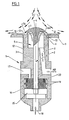
- a diffuser valve can comprise a body generally indicated by arrow 1, a valve member generally indicated by arrow 2, mounted within a body, said valve member comprising a stem 3 mounted for reciprocation in the body 1 and a valve head 4 opening to and positioned at one end of the body.
- the end of the diffuser valve is provided with a fluid outlet generally indicated by arrow 5 which includes a valve seat 6 upon which a valve face 7 of the valve head 4 can rest, and means such as passage 8 communicable with the fluid outlet 5 by which the valve may be connected to a fluid under pressure.
- the valve is constructed and arranged such that in use, with the valve mounted in the wall 9 of a container and the valve outlet extending into the interiors of an object (not shown). When fluid under pressure is applied to the fluid outlet 5 the valve member 2 opens to allow fluid to be dispersed via the outlet between the valve seat 6 and the valve face 7.
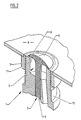
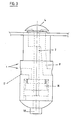
- valve is shown in an open position in Figures 1 and 3, and a closed position in Figure 2.
- valve is used as a diffuser valve to assist the passage of particulate materials from a hopper (not shown)
- a number of the valves can be positioned strategically about the walls of the hopper with the valve being mounted over apertures 10 therein and the valve body being fixed to a socket 11 ( Figure 2 only) which is fixed over the apertures 10.
- a convenient way to unite the socket and the body is to have an internal thread on the socket 11 and a matching external thread on the upper extremities 12 of the body 1 as indicated. When the valve member is fitted the valve is positioned such that extreme edges 13 of the body 1 are flush with the interiors of the wall 9 if the hopper and the outer extremities of the valve face extend above the inner surfaces of the wall 9 of the hopper.
- valve member 2 When a fluid such as compressed air is applied to the fluid outlet 5 the valve member 2 lifts and the valve face 7 is separated from the valve seat 6 which as indicated presents a knife- edge 6A to the valve face.
- the valve face 7 is provided with an arcuate surface, the outer extremities 7A of which overhang the valve seat 6 such that fluid escaping from the outlet is directed substantially at right angles to the lengthwise axis of the valve member and across the surfaces of the interiors of the hopper 9 substantially as indicated by the path arrows R in Figure 1 and particulate materials in the hopper and immediately surrounding the valve head 4 would tend to flow in the same direction as the path arrows S creating an inverted vortex in the region above the arcuate surface of the valve head 4.
- the valve When the hopper is empty the valve may be closed although as will be appreciated the valve may be used in an open position as required.
- valve member 2 may be normally biased in a closed position by having a biasing spring 20 acting on the valve stem which would be overcome when fluid under pressure enters the outlet 5.
- the fluid outlet 5 is a pressure equalising chamber which will ensure that equal pressure is provided about the periphery of the valve -face to lift the valve.
- valve body can incorporate a fluid chamber 15 at the end opposite to the fluid outlet and into which the valve stem 3 extends.
- the valve stem 3 can mount a piston 16 and an inlet means 17, 18 can be provided communicable with opposite sides of the piston such that when a fluid such as air at different pressures is applied to opposite sides of the piston this will cause the valve member to reciprocate to and from open and closed positions.
- the piston 16 can be provided with peripheral grooves 19 into which rubber 0- rings seals or the like (not shown) can be fitted.
- air at high pressure can be provided via inlet 8 and inlet 18 whilst air at a lower pressure (or a vacuum) can be applied at inlet 17. The valve will then move to an open position.
- valve can be moulded or fabricated in stainless steel, such being an excepted material for food industries where contact between machine and product is made during manufacturing processes.
- the valve could however be mounted or fabricated in other materials such as plastics.
- valve can be used to disperse a liquid into an object for the purpose of cleaning or fire fitting.
- the knife edge 6A of the valve seat 6 is designed to eliminate the possibility of particulate materials clogging up the valve outlet.
- the valve described can be conveniently fitted to existing installations by mounting the socket 11 in position as indicated and then fixing the valve and its connections.
- piston 16 is used to affect opening or closing of the valve then its cross-sectional area on the closing side can be made to be greater than the exposed cross-sectional area of the valve head so that a common pressure source can be applied to those areas.
Landscapes
- Engineering & Computer Science (AREA)
- Mechanical Engineering (AREA)
- Lift Valve (AREA)
- Compressor (AREA)
- Massaging Devices (AREA)
- Check Valves (AREA)
- Filling Or Emptying Of Bunkers, Hoppers, And Tanks (AREA)
- Input Circuits Of Receivers And Coupling Of Receivers And Audio Equipment (AREA)
Claims (3)
Priority Applications (1)
| Application Number | Priority Date | Filing Date | Title |
|---|---|---|---|
| AT85105098T ATE51599T1 (de) | 1984-04-30 | 1985-04-26 | Belueftungseinrichtung. |
Applications Claiming Priority (2)
| Application Number | Priority Date | Filing Date | Title |
|---|---|---|---|
| NZ207993A NZ207993A (en) | 1984-04-30 | 1984-04-30 | Lift-type check valve for use as diffuser valve in hopper |
| NZ207993 | 1984-04-30 |
Publications (3)
| Publication Number | Publication Date |
|---|---|
| EP0160281A2 EP0160281A2 (de) | 1985-11-06 |
| EP0160281A3 EP0160281A3 (en) | 1987-02-04 |
| EP0160281B1 true EP0160281B1 (de) | 1990-04-04 |
Family
ID=19920758
Family Applications (1)
| Application Number | Title | Priority Date | Filing Date |
|---|---|---|---|
| EP85105098A Expired - Lifetime EP0160281B1 (de) | 1984-04-30 | 1985-04-26 | Belüftungseinrichtung |
Country Status (6)
| Country | Link |
|---|---|
| US (1) | US4739964A (de) |
| EP (1) | EP0160281B1 (de) |
| AT (1) | ATE51599T1 (de) |
| AU (1) | AU582742B2 (de) |
| DE (1) | DE3576945D1 (de) |
| NZ (1) | NZ207993A (de) |
Families Citing this family (19)
| Publication number | Priority date | Publication date | Assignee | Title |
|---|---|---|---|---|
| GB2200344B (en) * | 1987-01-29 | 1990-10-17 | Beacon Services Limited | Devices for promoting flow of granular or like material within a container |
| JPH0641801Y2 (ja) * | 1989-01-13 | 1994-11-02 | 三菱重工業株式会社 | 粉粒体の供給装置 |
| US4934877A (en) * | 1989-02-06 | 1990-06-19 | Ellcon-National, Inc. | Pneumatic gate for railway hopper cars |
| DE9015587U1 (de) * | 1990-11-14 | 1991-01-31 | Feldbinder & Beckmann oHG, 2090 Winsen | Drucklufteinlaßrückschlagventil |
| US5143256A (en) * | 1991-04-22 | 1992-09-01 | Wadensten Theodore S | Gas accumulator and blaster apparatus |
| US5139175A (en) * | 1991-08-02 | 1992-08-18 | Cargo Tank Engineering, Inc. | Air distributing device |
| US5564825A (en) * | 1992-12-02 | 1996-10-15 | Shrader Canada Limited | Integral inlet valve and mixer to promote mixing of fluids in a tank |
| US5623820A (en) * | 1995-02-03 | 1997-04-29 | The Boeing Company | Flow control apparatus for gas turbine engine installation pressure relief doors |
| US6007234A (en) * | 1998-07-13 | 1999-12-28 | Dynamic Air, Inc. | Fluid injector |
| GB2430166A (en) * | 2005-08-02 | 2007-03-21 | Dps | Fluidising apparatus |
| US8087851B1 (en) | 2006-04-27 | 2012-01-03 | Jarvis R Darren | Process for handling powdered material |
| EP2174891A1 (de) * | 2008-10-07 | 2010-04-14 | Ateliers Caucheteux SPRL | Vorrichtung zum Verflüssigen von körnigen Stoffen, Behälter mit einer solchen Vorrichtung, Verfahren zur Aufbewahrung von körnigen Stoffen und Verfahren zum Verflüssigen von körnigen Stoffen in einem Behälter |
| DE202014002625U1 (de) * | 2014-03-25 | 2015-03-27 | Agrilux Beteiligungs Gmbh | Ausblassystem für Luftstoßgeräte |
| CZ29256U1 (cs) * | 2015-04-24 | 2016-03-15 | Mosa Solution S.R.O. | Otěruvzdorná pulzní tryska a systém uvolňování netekoucích sypkých materiálů |
| US9650206B2 (en) * | 2015-07-24 | 2017-05-16 | Dynamic Aur Inc. | Conveying systems |
| CN206229222U (zh) * | 2016-06-08 | 2017-06-09 | 亚泰半导体设备股份有限公司 | 桶底喷流搅拌装置 |
| IT201700071761A1 (it) * | 2017-06-27 | 2018-12-27 | Nol Tec Europe S R L | Organo soffiatore per miscelatori pneumatici ed apparato per la miscelazione pneumatica di granulati, polveri e/o liquidi comprendente tale organo soffiatore |
| IT201900010080A1 (it) * | 2019-06-26 | 2020-12-26 | Nol Tec Europe S R L | Apparecchiatura e procedimento per la miscelazione di granulati e/o polveri e/o liquidi negli impianti di produzione della gomma |
| WO2025178143A1 (ko) * | 2024-02-20 | 2025-08-28 | 엘지전자 주식회사 | 분체 보관통 |
Family Cites Families (7)
| Publication number | Priority date | Publication date | Assignee | Title |
|---|---|---|---|---|
| FR569411A (fr) * | 1922-08-04 | 1924-04-11 | Perfectionnements apportés aux obturateurs commandés à distance au moyen d'un fluide agissant sur un piston | |
| FR819848A (fr) * | 1936-06-30 | 1937-10-27 | Perfectionnements aux valves d'extraction | |
| FR1156173A (fr) * | 1955-08-29 | 1958-05-13 | Buss Ag | Dispositif d'arrêt pour réservoir de stockage de liquide ou de gaz |
| DE1909219C3 (de) * | 1969-02-24 | 1978-11-02 | Fendt, Wolfgang, Dr., 8032 Graefelfing | Pneumatische Einrichtung zur Produktaustragung aus Schüttgutbehältern |
| JPS533813B2 (de) * | 1973-12-26 | 1978-02-10 | ||
| AU4912279A (en) * | 1978-07-21 | 1981-01-22 | Kockums Industries (Australia) Pty. Ltd. | Storage vessel with fluidising means |
| US4261389A (en) * | 1978-12-05 | 1981-04-14 | Wacker-Chemie Gmbh | Gas injecting valve for suspensions |
-
1984
- 1984-04-30 NZ NZ207993A patent/NZ207993A/xx unknown
-
1985
- 1985-04-24 AU AU41672/85A patent/AU582742B2/en not_active Ceased
- 1985-04-26 EP EP85105098A patent/EP0160281B1/de not_active Expired - Lifetime
- 1985-04-26 AT AT85105098T patent/ATE51599T1/de not_active IP Right Cessation
- 1985-04-26 DE DE8585105098T patent/DE3576945D1/de not_active Expired - Lifetime
-
1986
- 1986-11-21 US US06/933,754 patent/US4739964A/en not_active Expired - Fee Related
Also Published As
| Publication number | Publication date |
|---|---|
| EP0160281A2 (de) | 1985-11-06 |
| US4739964A (en) | 1988-04-26 |
| AU4167285A (en) | 1985-11-07 |
| NZ207993A (en) | 1986-09-10 |
| EP0160281A3 (en) | 1987-02-04 |
| ATE51599T1 (de) | 1990-04-15 |
| AU582742B2 (en) | 1989-04-13 |
| DE3576945D1 (de) | 1990-05-10 |
Similar Documents
| Publication | Publication Date | Title |
|---|---|---|
| US4739964A (en) | Diffuser valve | |
| AU709501B2 (en) | Device for dispensing an air-liquid mixture, in particular foam, and operating unit intended therefor | |
| EP0882921B1 (de) | Kompaktes Ventil mit Rollmembranventilkörper | |
| US4730635A (en) | Valve and method | |
| US6951295B1 (en) | Flow control element and dispensing structure incorporating same | |
| US4822001A (en) | Positive fluid seal butterfly valve | |
| EP1043529B1 (de) | Hocheffizient- Ventil- und Sitzbaueinheit | |
| KR960703353A (ko) | 일체식 수송용 밀봉부를 갖는 절첩식 펌프실을 구비한 펌프장치(Pump device with collapsible pump chamber having integral shipping seal) | |
| JPS591363A (ja) | スクイ−ズボトルの分配装置 | |
| KR100604444B1 (ko) | 탱크 수송용 압력 릴리이프 밸브 조립체 | |
| BRPI0500078B1 (pt) | Assembly of aerator valve through positive pressure | |
| CA1172041A (en) | Compressed air dehumidifier | |
| US3744751A (en) | Check valve | |
| US20060261097A1 (en) | Dispensing valve | |
| KR950009981B1 (ko) | 액화 가스 통 밸브 장치 | |
| US7461829B2 (en) | Valve for controlling slurry flow | |
| GB1589381A (en) | Pneumatic dispensers for viscous materials | |
| EP0571070A3 (de) | Wiederfüllen verhindernder Behälterverschluss | |
| US20230071670A1 (en) | Valve | |
| EP0063752A2 (de) | Durchspülbarer Verteiler für Membran-bedienten Bauteil | |
| US3191622A (en) | Dispensing valve | |
| US2732263A (en) | Diverter valves for pneumatic | |
| WO2000026120A3 (en) | Materials handling apparatus | |
| EP0406936A1 (de) | Einwegmembranventil mit gesteuertem Zentralhub | |
| JP4336564B2 (ja) | リリーフ機構を備えた流量設定器 |
Legal Events
| Date | Code | Title | Description |
|---|---|---|---|
| PUAI | Public reference made under article 153(3) epc to a published international application that has entered the european phase |
Free format text: ORIGINAL CODE: 0009012 |
|
| AK | Designated contracting states |
Designated state(s): AT BE CH DE FR GB IT LI NL SE |
|
| PUAL | Search report despatched |
Free format text: ORIGINAL CODE: 0009013 |
|
| AK | Designated contracting states |
Kind code of ref document: A3 Designated state(s): AT BE CH DE FR GB IT LI NL SE |
|
| 17P | Request for examination filed |
Effective date: 19870715 |
|
| 17Q | First examination report despatched |
Effective date: 19880310 |
|
| ITF | It: translation for a ep patent filed | ||
| GRAA | (expected) grant |
Free format text: ORIGINAL CODE: 0009210 |
|
| RIN1 | Information on inventor provided before grant (corrected) |
Inventor name: HUTT, JAMES JOSEPH |
|
| AK | Designated contracting states |
Kind code of ref document: B1 Designated state(s): AT BE CH DE FR GB IT LI NL SE |
|
| REF | Corresponds to: |
Ref document number: 51599 Country of ref document: AT Date of ref document: 19900415 Kind code of ref document: T |
|
| ET | Fr: translation filed | ||
| REF | Corresponds to: |
Ref document number: 3576945 Country of ref document: DE Date of ref document: 19900510 |
|
| PLBE | No opposition filed within time limit |
Free format text: ORIGINAL CODE: 0009261 |
|
| STAA | Information on the status of an ep patent application or granted ep patent |
Free format text: STATUS: NO OPPOSITION FILED WITHIN TIME LIMIT |
|
| 26N | No opposition filed | ||
| PGFP | Annual fee paid to national office [announced via postgrant information from national office to epo] |
Ref country code: FR Payment date: 19910513 Year of fee payment: 7 |
|
| PG25 | Lapsed in a contracting state [announced via postgrant information from national office to epo] |
Ref country code: FR Effective date: 19911230 |
|
| REG | Reference to a national code |
Ref country code: FR Ref legal event code: ST |
|
| ITTA | It: last paid annual fee | ||
| EAL | Se: european patent in force in sweden |
Ref document number: 85105098.9 |
|
| PGFP | Annual fee paid to national office [announced via postgrant information from national office to epo] |
Ref country code: SE Payment date: 19980416 Year of fee payment: 14 |
|
| PGFP | Annual fee paid to national office [announced via postgrant information from national office to epo] |
Ref country code: AT Payment date: 19980423 Year of fee payment: 14 |
|
| PGFP | Annual fee paid to national office [announced via postgrant information from national office to epo] |
Ref country code: BE Payment date: 19980429 Year of fee payment: 14 |
|
| PGFP | Annual fee paid to national office [announced via postgrant information from national office to epo] |
Ref country code: NL Payment date: 19980430 Year of fee payment: 14 |
|
| PGFP | Annual fee paid to national office [announced via postgrant information from national office to epo] |
Ref country code: DE Payment date: 19980528 Year of fee payment: 14 |
|
| PGFP | Annual fee paid to national office [announced via postgrant information from national office to epo] |
Ref country code: CH Payment date: 19980717 Year of fee payment: 14 |
|
| PGFP | Annual fee paid to national office [announced via postgrant information from national office to epo] |
Ref country code: GB Payment date: 19990415 Year of fee payment: 15 |
|
| PG25 | Lapsed in a contracting state [announced via postgrant information from national office to epo] |
Ref country code: AT Free format text: LAPSE BECAUSE OF NON-PAYMENT OF DUE FEES Effective date: 19990426 |
|
| PG25 | Lapsed in a contracting state [announced via postgrant information from national office to epo] |
Ref country code: SE Free format text: LAPSE BECAUSE OF NON-PAYMENT OF DUE FEES Effective date: 19990427 |
|
| PG25 | Lapsed in a contracting state [announced via postgrant information from national office to epo] |
Ref country code: LI Free format text: LAPSE BECAUSE OF NON-PAYMENT OF DUE FEES Effective date: 19990430 Ref country code: CH Free format text: LAPSE BECAUSE OF NON-PAYMENT OF DUE FEES Effective date: 19990430 Ref country code: BE Free format text: LAPSE BECAUSE OF NON-PAYMENT OF DUE FEES Effective date: 19990430 |
|
| BERE | Be: lapsed |
Owner name: HUTT JAMES JOSEPH Effective date: 19990430 |
|
| PG25 | Lapsed in a contracting state [announced via postgrant information from national office to epo] |
Ref country code: NL Free format text: LAPSE BECAUSE OF NON-PAYMENT OF DUE FEES Effective date: 19991101 |
|
| REG | Reference to a national code |
Ref country code: CH Ref legal event code: PL |
|
| NLV4 | Nl: lapsed or anulled due to non-payment of the annual fee |
Effective date: 19991101 |
|
| EUG | Se: european patent has lapsed |
Ref document number: 85105098.9 |
|
| PG25 | Lapsed in a contracting state [announced via postgrant information from national office to epo] |
Ref country code: DE Free format text: LAPSE BECAUSE OF NON-PAYMENT OF DUE FEES Effective date: 20000201 |
|
| PG25 | Lapsed in a contracting state [announced via postgrant information from national office to epo] |
Ref country code: GB Free format text: LAPSE BECAUSE OF NON-PAYMENT OF DUE FEES Effective date: 20000426 |
|
| GBPC | Gb: european patent ceased through non-payment of renewal fee |
Effective date: 20000426 |