EP0160492B1 - Method and device for the casting of concrete products - Google Patents
Method and device for the casting of concrete products Download PDFInfo
- Publication number
- EP0160492B1 EP0160492B1 EP85302823A EP85302823A EP0160492B1 EP 0160492 B1 EP0160492 B1 EP 0160492B1 EP 85302823 A EP85302823 A EP 85302823A EP 85302823 A EP85302823 A EP 85302823A EP 0160492 B1 EP0160492 B1 EP 0160492B1
- Authority
- EP
- European Patent Office
- Prior art keywords
- cavity
- mandrel
- mandrels
- casting
- mix
- Prior art date
- Legal status (The legal status is an assumption and is not a legal conclusion. Google has not performed a legal analysis and makes no representation as to the accuracy of the status listed.)
- Expired - Lifetime
Links
- 238000005266 casting Methods 0.000 title claims description 27
- 238000000034 method Methods 0.000 title claims description 20
- 239000000203 mixture Substances 0.000 claims description 26
- 230000000737 periodic effect Effects 0.000 claims description 5
- 238000009415 formwork Methods 0.000 description 14
- 238000010276 construction Methods 0.000 description 2
- 230000002706 hydrostatic effect Effects 0.000 description 2
- 238000011437 continuous method Methods 0.000 description 1
- 230000008878 coupling Effects 0.000 description 1
- 238000010168 coupling process Methods 0.000 description 1
- 238000005859 coupling reaction Methods 0.000 description 1
- 230000000694 effects Effects 0.000 description 1
- 239000012530 fluid Substances 0.000 description 1
- 230000001360 synchronised effect Effects 0.000 description 1
Images




Classifications
-
- B—PERFORMING OPERATIONS; TRANSPORTING
- B28—WORKING CEMENT, CLAY, OR STONE
- B28B—SHAPING CLAY OR OTHER CERAMIC COMPOSITIONS; SHAPING SLAG; SHAPING MIXTURES CONTAINING CEMENTITIOUS MATERIAL, e.g. PLASTER
- B28B3/00—Producing shaped articles from the material by using presses; Presses specially adapted therefor
- B28B3/20—Producing shaped articles from the material by using presses; Presses specially adapted therefor wherein the material is extruded
- B28B3/22—Producing shaped articles from the material by using presses; Presses specially adapted therefor wherein the material is extruded by screw or worm
- B28B3/228—Slipform casting extruder, e.g. self-propelled extruder
-
- B—PERFORMING OPERATIONS; TRANSPORTING
- B28—WORKING CEMENT, CLAY, OR STONE
- B28B—SHAPING CLAY OR OTHER CERAMIC COMPOSITIONS; SHAPING SLAG; SHAPING MIXTURES CONTAINING CEMENTITIOUS MATERIAL, e.g. PLASTER
- B28B1/00—Producing shaped prefabricated articles from the material
- B28B1/08—Producing shaped prefabricated articles from the material by vibrating or jolting
- B28B1/084—Producing shaped prefabricated articles from the material by vibrating or jolting the vibrating moulds or cores being moved horizontally for making strands of moulded articles
-
- B—PERFORMING OPERATIONS; TRANSPORTING
- B28—WORKING CEMENT, CLAY, OR STONE
- B28B—SHAPING CLAY OR OTHER CERAMIC COMPOSITIONS; SHAPING SLAG; SHAPING MIXTURES CONTAINING CEMENTITIOUS MATERIAL, e.g. PLASTER
- B28B7/00—Moulds; Cores; Mandrels
- B28B7/16—Moulds for making shaped articles with cavities or holes open to the surface, e.g. with blind holes
- B28B7/18—Moulds for making shaped articles with cavities or holes open to the surface, e.g. with blind holes the holes passing completely through the article
- B28B7/186—Moulds for making shaped articles with cavities or holes open to the surface, e.g. with blind holes the holes passing completely through the article for plates, panels or similar sheet- or disc-shaped objects, also flat oblong moulded articles with lateral openings, e.g. panels with openings for doors or windows, grated girders
-
- B—PERFORMING OPERATIONS; TRANSPORTING
- B28—WORKING CEMENT, CLAY, OR STONE
- B28B—SHAPING CLAY OR OTHER CERAMIC COMPOSITIONS; SHAPING SLAG; SHAPING MIXTURES CONTAINING CEMENTITIOUS MATERIAL, e.g. PLASTER
- B28B7/00—Moulds; Cores; Mandrels
- B28B7/28—Cores; Mandrels
Definitions
- the present invention is concerned with a method of casting an oblong concrete product having one or more longitudinal cavities, either by means of a periodic method or by means of a continuous slide casting method, wherein each cavity is formed in the concrete product by means of a cavity mandrel.
- the invention is also concerned with a device for casting a concrete product either by means of a periodic method or by means of a continuous slide casting method, the device comprising a bottom plane and side walls as well as one or more displaceable cavity mandrels each for forming a cavity in the product to be cast.
- a cavity is supposed to be understood herein as also meaning longitudinal recesses in the concrete product with one of the sides of the recesses open.
- the casting formwork comprises a bottom plane, side walls, as well as tubes passing through the formwork, the cavities being formed in the slab to be cast in the positions of the said tubes.
- so-called semi-viscous mix is used, with which the formwork is filled. After the compacting of the mix, the tubes are pulled out of the cavities.
- the slide casting method is a continuous method, and therein it is possible to use a highly viscous mix.
- the mix is fed into the formwork by means of feed screws.
- Cavity mandrels with internal vibrators are provided as extensions of the feed screws, which mandrels compact the mix.
- the machine moves along its base on wheels, while the hollow slab is extruded from one of its ends.
- a problem in particular in a tube-pulling device is how to compact the mix in the portions of the slab placed underneath the tubes.
- a drawback consists in the noise caused by the vibrator.
- British Patent Specification (GB-A-) No. 907450 discloses a slide casting machine in which vibrators are not used because the mandrels are rotated continuously in the same direction in order to compact the concrete mix.
- the method in accordance with the present invention is characterised in that pressurized concrete mix is compacted by rotating the cavity mandrel back and forth around its longitudinal axis, the cavity mandrel having a non-circular cross-section.
- the device in accordance with the invention is characterised in that each cavity mandrel is arranged to be rotated back and forth around its longitudinal axis and has a non-circular cross-section.
- the tube-pulling device shown in Fig. 1 in itself known, is provided with a base 1, onto which the frame 2 of the formwork is laid.
- the pivotable side walls 3 are pivoted to the sides of the formwork, and the tubes 4 are pushed into the formwork.
- the casting mix is poured into the mould, and the mix is compacted by making use of the hydrostatic pressure of the mix and by vibrating the mix.
- the tubes 4 are again pulled out of the formwork to the other end of the device, and the casting is repeated with a new formwork.
- Figures 2 and 3 show the arm construction for moving the tubes 4 in the tube-pulling device, in accordance with the present invention, back and forth around their longitudinal axes.
- the arm construction may be fitted in the machine shown, in Fig. 1, e.g., at the right-side end in the figure.
- the shafts 5 are connected to the turning arms 6. Every other turning arm 6 is connected by means of the articulated joint 7 to the transverse arm 8, and every other turning arm 6' is connected by means of the articulated joint 7' to the transverse arm 8'.
- Connecting rods 10 and 10' are attached to one end of the transverse arms 8 and 8' by means of articulated joints 9 and 9', and the said connecting rods 10 and 10' are attached to a rotary disc 11 eccentrically.
- the arms 8 and 8' move back and forth in opposite directions.
- the tubes 4, attached to the shafts 5 permanently are turned along with the shafts 5 back and forth over a certain angle, so that two tubes placed side by side are always turned in opposite directions relative each other.
- the magnitude of the turning angle is at the maximum 180°, preferably no more than 90°, in particular 5 to 50°, and the frequency of the swinging movement is, e.g., 2 to 10 c/s.
- the casting mix is relatively fluid and adheres partly to the tubes 4, particularly as the tubes are not of circular section.
- the movement of the tubes is transferred into the mix and compacts and shifts the mix into the poorly compacted portions of the casting object.
- Fig. 4 shows a tube 4 section that is close to square. When such a shape is used, economies are obtained in the quantity of casting mix, and the weight of the slab to be cast is reduced.
- An appropriate width a of the turning angle of the tube is, for the section shown in Fig. 4, for example, about 20°. The appropriate turning angle depends on the diameter of the tube. Measured on the circumference of the tube, an appropriate amplitude of the movement is about 2 to 20 mm.
- Adjoining tubes may be moved as synchronized relative each other in opposite directions or in the same direction.
- the turning movement may be produced, besides mechanically, also hydraulically or pneumatically.
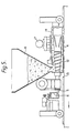
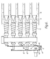
- FIGS 5 and 6 show a slide casting machine for the application of the invention.
- the feeder spiral 12 is fitted on a cone widening towards the final end of the machine.
- a cavity mandrel 4 is fitted.
- several feeder spirals and cavity mandrels are fitted side by side.
- the machine further comprises side boards 13 and a deck board 14, a base 15, along which the machine travels in the direction indicated by the arrow, a feeder funnel 16 for feeding the concrete into the formwork, and a vibrator 17.
- the above is in itself known from conventional slide casting machines.
- the cavity mandrel 4 is fixed stationarily to the shaft 5 passing through the spiral 12.
- the shafts 5 are attached to turning arms 6, which are further linked to two transverse arms 8 and 8' in a way corresponding to the tube-pulling device shown in Figures 2 and 3.
- the connecting rods 10 and 10' are, in this embodiment, attached eccentrically to two separate discs 11 and 11'.
- the arms 8 and 8' perform a movement back and forth and swing the turning arms 6 and 6', whereby the shafts 5 and, along with them, the cavity mandrels 4 perform a turning movement back and forth around their longitudinal axis.
- FIGs 7 and 8 show another solution for a slide casting machine in accordance with the invention.
- the feeder spirals 12 in the device of Figures 5 and 6 have been replaced by feeder screws 12 fitted above the mandrels 4, in a diagonal position between the mandrels.
- the screws 12, which generate the pressure in the concrete mix feed the mix onto the mandrels 4, which are moved in accordance with the invention by means of the arms 6 back and forth. Thereby the mix is compacted. If necessary, the compacting effect is intensified, e.g., by means of a vibrator 17.
- Fig. 9 shows a mandrel 4 consisting of three parts, which said parts 4', 4" and 4'" are interconnected by means of resilient rubber coupling components 18.
- the feed end 4' of the mandrel is moved by means of the shaft 5 back and forth, the movement of the mandrel in its different parts becomes smaller towards the trailing end 4"' of the mandrel.
- the cross-section of the mandrel part is shaped so that it differs from circular, whereby the trailing end moves very little and leaves a smooth cavity.
- Fig. 10 shows a further, simple compacting device in accordance with the invention.
- the concrete mix is introduced onto the mandrels 4 by means of an appropriate conveyor device or vessel (not shown in the figure).
- the compacting device 19 consists of two or three rolls 20, over which an endless mat 21 runs.
- the compacting device presses the concrete into the formwork and against the mandrels 4.
- the mandrels 4, which consist of 3 parts, move in accordance with the invention back and forth around their longitudinal axis and compact the pressurized mix.
- the casting device is shifted forwards in the direction of the arrow along the base 15 of the formwork as compacting has taken place.
- the concrete mix may also be pressurized by using a sufficiently high feeder funnel, whereby the hydrostatic pressure produces an adequate pressure in the formwork around the mandrels 4.
Landscapes
- Engineering & Computer Science (AREA)
- Manufacturing & Machinery (AREA)
- Chemical & Material Sciences (AREA)
- Ceramic Engineering (AREA)
- Mechanical Engineering (AREA)
- Manufacturing Of Tubular Articles Or Embedded Moulded Articles (AREA)
- On-Site Construction Work That Accompanies The Preparation And Application Of Concrete (AREA)
- Press-Shaping Or Shaping Using Conveyers (AREA)
- Devices For Post-Treatments, Processing, Supply, Discharge, And Other Processes (AREA)
- Separation By Low-Temperature Treatments (AREA)
- Treatment Of Steel In Its Molten State (AREA)
- Sampling And Sample Adjustment (AREA)
Applications Claiming Priority (2)
| Application Number | Priority Date | Filing Date | Title |
|---|---|---|---|
| FI841612A FI73170C (fi) | 1984-04-24 | 1984-04-24 | Foerfarande och anordning foer gjutning av betongprodukter. |
| FI841612 | 1984-04-24 |
Publications (2)
| Publication Number | Publication Date |
|---|---|
| EP0160492A1 EP0160492A1 (en) | 1985-11-06 |
| EP0160492B1 true EP0160492B1 (en) | 1990-08-29 |
Family
ID=8518957
Family Applications (1)
| Application Number | Title | Priority Date | Filing Date |
|---|---|---|---|
| EP85302823A Expired - Lifetime EP0160492B1 (en) | 1984-04-24 | 1985-04-23 | Method and device for the casting of concrete products |
Country Status (11)
| Country | Link |
|---|---|
| US (1) | US4668447A (cs) |
| EP (1) | EP0160492B1 (cs) |
| JP (1) | JPS61104802A (cs) |
| CA (1) | CA1264108A (cs) |
| CS (1) | CS262657B2 (cs) |
| DE (1) | DE3579354D1 (cs) |
| DK (1) | DK162030C (cs) |
| ES (1) | ES8606063A1 (cs) |
| FI (1) | FI73170C (cs) |
| NO (1) | NO160497C (cs) |
| RU (1) | RU2031780C1 (cs) |
Families Citing this family (11)
| Publication number | Priority date | Publication date | Assignee | Title |
|---|---|---|---|---|
| FI74648C (fi) * | 1984-01-19 | 1988-03-10 | Partek Ab | Foerfarande och glidgjutningsmaskin foer gjutning av haolelement av betong. |
| FI850837A0 (fi) * | 1985-03-01 | 1985-03-01 | Kt Suunnittelu Oy | Glidgjutmaskin foer framstaellning av betongelement. |
| FI76518B (fi) * | 1986-01-17 | 1988-07-29 | Kt Suunnittelu Oy | Foerfarande och anordning foer formning av bindspaor i sidoytorna hos ett betongelement. |
| FI76514C (fi) * | 1986-04-07 | 1989-07-31 | Kt Suunnittelu Oy | Foerfarande och anordning foer gjutning av betongelement. |
| FI83986C (fi) * | 1987-06-18 | 1991-09-25 | Parma Oy | Glidgjutmaskin foer framstaellning av laongstraeckta betongstycken. |
| FI84575C (fi) * | 1988-09-14 | 1991-12-27 | Partek Ab | Foerfarande och glidgjutningsmaskin foer gjutning av en eller flera parallella betongprodukter. |
| AU710280B2 (en) * | 1995-08-18 | 1999-09-16 | Boral Resources (Qld) Pty Limited | Block moulding apparatus |
| AT2587U3 (de) * | 1998-07-30 | 1999-04-26 | Vs Hohldielen West Ges M B H | Fertigteilkamin und verfahren zu dessen herstellung |
| FI20030733L (fi) * | 2003-05-15 | 2004-11-16 | X Tec Oy Ltd | Menetelmä ja sovitelma betonituotteen valmistamiseksi |
| FI20031534A7 (fi) * | 2003-10-20 | 2005-04-21 | Elematic Oy Ab | Menetelmä ja laitteisto betonielementtien valamiseksi |
| WO2013173030A1 (en) * | 2012-05-14 | 2013-11-21 | Hawkeye Concrete Products Co. | Concrete roller head |
Family Cites Families (10)
| Publication number | Priority date | Publication date | Assignee | Title |
|---|---|---|---|---|
| ES249605A1 (es) * | 1959-05-05 | 1959-09-16 | Vinas Tarres Juan | Sistema de fabricacion continua de piezas huecas de hormigon |
| US3200177A (en) * | 1963-04-04 | 1965-08-10 | Clarence Riegel | Method of forming concrete articles and slip forming machine therefor |
| DK111555B (da) * | 1966-12-09 | 1968-09-09 | Dansk Spaend As | Fremgangsmåde ved successiv forskydning eller udtrækning af et flertal parallelle kerner i en støbeform til fremstilling af udkernede betonelementer og anlæg til udførelse af denne fremgangsmåde. |
| SE322720B (cs) * | 1967-06-29 | 1970-04-13 | P Jonell | |
| US3877860A (en) * | 1969-12-04 | 1975-04-15 | Dyform Concrete Prestressed Lt | Extrusion machine for making articles of cement-like material |
| US4133619A (en) * | 1976-09-10 | 1979-01-09 | The Flexicore Co., Inc. | Extrusion casting apparatus |
| FI62783C (fi) * | 1977-08-10 | 1983-03-10 | Paraisten Kalkki Oy | Glidgjutmaskin avsedd att anvaendas foer framstaellning av haolplattor och liknande |
| CA1105244A (en) * | 1978-05-03 | 1981-07-21 | George Putti | Machine for extruding hollow cored concrete sections |
| US4229153A (en) * | 1979-03-08 | 1980-10-21 | Hight Jr Henry D | Apparatus for use in slip forming structural concrete members |
| FI69591C (fi) * | 1983-02-09 | 1986-03-10 | Asko Sarja | Foerfarande och anordning foer komprimering av betong |
-
1984
- 1984-04-24 FI FI841612A patent/FI73170C/fi not_active IP Right Cessation
-
1985
- 1985-04-18 JP JP60083593A patent/JPS61104802A/ja not_active Expired - Lifetime
- 1985-04-22 NO NO851585A patent/NO160497C/no not_active IP Right Cessation
- 1985-04-22 CS CS852958A patent/CS262657B2/cs unknown
- 1985-04-23 CA CA000479853A patent/CA1264108A/en not_active Expired - Lifetime
- 1985-04-23 DK DK180885A patent/DK162030C/da not_active IP Right Cessation
- 1985-04-23 DE DE8585302823T patent/DE3579354D1/de not_active Expired - Lifetime
- 1985-04-23 EP EP85302823A patent/EP0160492B1/en not_active Expired - Lifetime
- 1985-04-23 RU SU853883104A patent/RU2031780C1/ru active
- 1985-04-23 ES ES542506A patent/ES8606063A1/es not_active Expired
- 1985-04-24 US US06/726,660 patent/US4668447A/en not_active Expired - Lifetime
Also Published As
| Publication number | Publication date |
|---|---|
| CS295885A2 (en) | 1988-08-16 |
| FI73170B (fi) | 1987-05-29 |
| FI841612A0 (fi) | 1984-04-24 |
| CS262657B2 (en) | 1989-03-14 |
| DK180885D0 (da) | 1985-04-23 |
| NO851585L (no) | 1985-10-25 |
| DK162030C (da) | 1992-02-10 |
| DK162030B (da) | 1991-09-09 |
| NO160497B (no) | 1989-01-16 |
| FI841612L (fi) | 1985-10-25 |
| ES542506A0 (es) | 1986-04-01 |
| US4668447A (en) | 1987-05-26 |
| FI73170C (fi) | 1990-02-16 |
| DK180885A (da) | 1985-10-25 |
| DE3579354D1 (de) | 1990-10-04 |
| RU2031780C1 (ru) | 1995-03-27 |
| JPS61104802A (ja) | 1986-05-23 |
| CA1264108A (en) | 1990-01-02 |
| NO160497C (no) | 1989-04-26 |
| EP0160492A1 (en) | 1985-11-06 |
| ES8606063A1 (es) | 1986-04-01 |
Similar Documents
| Publication | Publication Date | Title |
|---|---|---|
| EP0125084B1 (en) | Method of and slide-casting machine for the casting of hollow slabs out of concrete | |
| US4668447A (en) | Method and device for the casting of concrete products | |
| CA1046245A (en) | Extrusion casting apparatus | |
| CA1256678A (en) | Method and slide-casting machine for the casting of hollow precast units of concrete | |
| FI84575B (fi) | Foerfarande och glidgjutningsmaskin foer gjutning av en eller flera parallella betongprodukter. | |
| FI67320C (fi) | Foerfarande och glidgjutanordning foer gjutning av betongstycken | |
| EP0192884B1 (en) | Method and device for the slide-casting of concrete hollow products | |
| FI85350C (fi) | Glidgjutmaskin foer framstaellning av betongelement och isynnerhet haolelement | |
| WO1983001593A1 (en) | Method for continuous casting of objects out of a high-viscosity casting mix as well as a slide-casting mould for carrying out the method | |
| EP0846534A1 (en) | Method and apparatus for casting concrete products | |
| US2501136A (en) | Machine for molding concrete and the like | |
| EP1212180B1 (en) | Method and apparatus for manufacturing a concrete product | |
| EP0592183B1 (en) | A method and an apparatus for casting concrete products | |
| SU977181A1 (ru) | Бетоноукладчик | |
| SU742136A1 (ru) | Виброзаглаживающее устройство | |
| CA1205986A (en) | Machine for casting concrete members | |
| FI74650C (fi) | Foerfarande och glidgjutningsmaskin foer gjutning av haolelement av betong. | |
| SU1265051A1 (ru) | Бетоноукладчик |
Legal Events
| Date | Code | Title | Description |
|---|---|---|---|
| PUAI | Public reference made under article 153(3) epc to a published international application that has entered the european phase |
Free format text: ORIGINAL CODE: 0009012 |
|
| AK | Designated contracting states |
Designated state(s): BE DE FR GB IT NL SE |
|
| 17P | Request for examination filed |
Effective date: 19860417 |
|
| 17Q | First examination report despatched |
Effective date: 19881014 |
|
| ITF | It: translation for a ep patent filed | ||
| GRAA | (expected) grant |
Free format text: ORIGINAL CODE: 0009210 |
|
| AK | Designated contracting states |
Kind code of ref document: B1 Designated state(s): BE DE FR GB IT NL SE |
|
| REF | Corresponds to: |
Ref document number: 3579354 Country of ref document: DE Date of ref document: 19901004 |
|
| ET | Fr: translation filed | ||
| PLBE | No opposition filed within time limit |
Free format text: ORIGINAL CODE: 0009261 |
|
| STAA | Information on the status of an ep patent application or granted ep patent |
Free format text: STATUS: NO OPPOSITION FILED WITHIN TIME LIMIT |
|
| 26N | No opposition filed | ||
| ITTA | It: last paid annual fee | ||
| EAL | Se: european patent in force in sweden |
Ref document number: 85302823.1 |
|
| REG | Reference to a national code |
Ref country code: GB Ref legal event code: IF02 |
|
| PGFP | Annual fee paid to national office [announced via postgrant information from national office to epo] |
Ref country code: FR Payment date: 20040330 Year of fee payment: 20 |
|
| PGFP | Annual fee paid to national office [announced via postgrant information from national office to epo] |
Ref country code: SE Payment date: 20040331 Year of fee payment: 20 |
|
| PGFP | Annual fee paid to national office [announced via postgrant information from national office to epo] |
Ref country code: GB Payment date: 20040405 Year of fee payment: 20 |
|
| PGFP | Annual fee paid to national office [announced via postgrant information from national office to epo] |
Ref country code: NL Payment date: 20040415 Year of fee payment: 20 |
|
| PGFP | Annual fee paid to national office [announced via postgrant information from national office to epo] |
Ref country code: BE Payment date: 20040422 Year of fee payment: 20 |
|
| PGFP | Annual fee paid to national office [announced via postgrant information from national office to epo] |
Ref country code: DE Payment date: 20040427 Year of fee payment: 20 |
|
| PG25 | Lapsed in a contracting state [announced via postgrant information from national office to epo] |
Ref country code: GB Free format text: LAPSE BECAUSE OF EXPIRATION OF PROTECTION Effective date: 20050422 |
|
| PG25 | Lapsed in a contracting state [announced via postgrant information from national office to epo] |
Ref country code: NL Free format text: LAPSE BECAUSE OF EXPIRATION OF PROTECTION Effective date: 20050423 |
|
| BE20 | Be: patent expired |
Owner name: *OY PARTEK A.B. Effective date: 20050423 |
|
| REG | Reference to a national code |
Ref country code: GB Ref legal event code: PE20 |
|
| EUG | Se: european patent has lapsed | ||
| NLV7 | Nl: ceased due to reaching the maximum lifetime of a patent |
Effective date: 20050423 |
|
| BE20 | Be: patent expired |
Owner name: *OY PARTEK A.B. Effective date: 20050423 |