EP0160641B1 - Station de pompage - Google Patents
Station de pompage Download PDFInfo
- Publication number
- EP0160641B1 EP0160641B1 EP83903594A EP83903594A EP0160641B1 EP 0160641 B1 EP0160641 B1 EP 0160641B1 EP 83903594 A EP83903594 A EP 83903594A EP 83903594 A EP83903594 A EP 83903594A EP 0160641 B1 EP0160641 B1 EP 0160641B1
- Authority
- EP
- European Patent Office
- Prior art keywords
- pump
- valve
- discharge pipe
- pump unit
- guide
- Prior art date
- Legal status (The legal status is an assumption and is not a legal conclusion. Google has not performed a legal analysis and makes no representation as to the accuracy of the status listed.)
- Expired
Links
- 239000002351 wastewater Substances 0.000 claims abstract description 7
- 239000007788 liquid Substances 0.000 claims description 3
- 230000002093 peripheral effect Effects 0.000 description 3
- 238000007689 inspection Methods 0.000 description 2
- 238000012423 maintenance Methods 0.000 description 2
- 238000013459 approach Methods 0.000 description 1
- 238000004140 cleaning Methods 0.000 description 1
- 238000010276 construction Methods 0.000 description 1
- 230000000694 effects Effects 0.000 description 1
- 238000007789 sealing Methods 0.000 description 1
- 238000009423 ventilation Methods 0.000 description 1
Images

Classifications
-
- F—MECHANICAL ENGINEERING; LIGHTING; HEATING; WEAPONS; BLASTING
- F04—POSITIVE - DISPLACEMENT MACHINES FOR LIQUIDS; PUMPS FOR LIQUIDS OR ELASTIC FLUIDS
- F04D—NON-POSITIVE-DISPLACEMENT PUMPS
- F04D29/00—Details, component parts, or accessories
- F04D29/60—Mounting; Assembling; Disassembling
- F04D29/605—Mounting; Assembling; Disassembling specially adapted for liquid pumps
- F04D29/606—Mounting in cavities
- F04D29/607—Mounting in cavities means for positioning from outside
-
- F—MECHANICAL ENGINEERING; LIGHTING; HEATING; WEAPONS; BLASTING
- F04—POSITIVE - DISPLACEMENT MACHINES FOR LIQUIDS; PUMPS FOR LIQUIDS OR ELASTIC FLUIDS
- F04D—NON-POSITIVE-DISPLACEMENT PUMPS
- F04D13/00—Pumping installations or systems
- F04D13/02—Units comprising pumps and their driving means
- F04D13/06—Units comprising pumps and their driving means the pump being electrically driven
- F04D13/08—Units comprising pumps and their driving means the pump being electrically driven for submerged use
- F04D13/086—Units comprising pumps and their driving means the pump being electrically driven for submerged use the pump and drive motor are both submerged
Definitions
- the invention relates to a pump station comprising an upper part suitable as control room and a lower part for collecting liquid, preferably waste water, one or more pumps located in said lower part, which are connected to a discharge pipe via valve means, each valve means comprising a stop valve, which is fixedly connected with the discharge pipe, and a non-return valve, which together with the corresponding pump is arranged in a pump unit, each pump unit being connectable to and detachable from the discharge pipe, and further comprising guide means for guiding the pump units from the lower operational position to an upper position, where they are accessible to repair and/or replacement.
- a pump station of this kind is known from SE-B-422 484.
- This known pump station has the following advantages. Both the pumps and the non-return valves of a pump station need frequent service, cleaning activities etc., whereas the stop valves are not critical with this rsepect. Those parts which need most attention i.e. the pump and the non-return valves can be easily inspected and/or repaired by lifting the pump units with the pumps and non-return valves from the lower part of the pump station to the upper part of the pump station. Thus, easy repair and maintenance of these parts is possible without excessive tubing which would be required if pumps and return valves would be located in the upper part of the pump station.
- the object of the invention is to provide a better and simpler construction.
- each guide is pivotable about a longitudinal axis and is connected to a stop valve so that by rotating a guide the stop valve cooperating therewith can be opened and closed.
- each guide is a hollow pipe and contains an extended shaft with which the cooperating stop valve can be opened and closed.
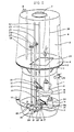
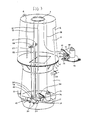
- FIG. 1 is the lower part of a previously pump station consisting of two parts located one on top of the other.
- the lower part 1 is provied at the top with a peripheral flange 2 and supports 3 for said peripheral flange.
- a floor 4 is located on the peripheral flange, and above the floor there is an upper part 5 having a door 6, a skylight 7 and a ventilation pipe 8.
- the lower part 1 is provided with a pipe socket 49 for connection of a pipe supplying the lower part 1 with waste water.
- the lower part is connected to a discharge pipe 10.
- Two units 11 and 12 are arranged in the bottom of the lower part, each consisting of a pump and a non-return valve. In the unit 11 the pump is designated 13 and the non-return valve 14.
- the pump is designated 15 and the non-return valve 16.
- Non-return valves 14 and 16 may be KG non-return valves PN 10, marketed by Ahlsell & Agren and described in their prospectus sheet for September, 1976.
- the orifice of connecting part 19 outside the lower part 1 is in a pipe socket 9 for connection to the discharge pipe 10.
- the connecting part 19 is provided with a foot 30 for mounting same on the bottom of the lower part 1.
- each non-return valve is provided with a flap which blocks the flow in reverse direction.
- the unit comprising pump and non-return valve will be termed "pump unit" in the following.
- the pump unit 11 is provided with an outlet opening surrounded by a flange 17.
- the flange 17 and edge of the outlet opening together form a flat contact surface abutting and cooperating with the branch pipe 18 of the connecting part 19.
- the branch pipe 18 forms an inlet opening to the connecting part 19 and has a flat end surface cooperating with the flat surface of the pump unit at its outlet opening.
- the branch pipe 18 is also provided with a flange 20 like the outlet opening to the pump unit 11.
- the pump unit 12 is connected to a branch pipe 21 also having a contact flange 22 and the pump unit 12 having a contact flange 23.
- Each branch pipe 18 and 21 has a stop valve 24 and 25, respectively.
- the stop valve may be a Beta sluice valve NT 4 of make Ahlsell & Agren.
- Such a sluice valve is described in prospectus AA-No. 580008.
- An operating shaft 26 is attached to the stop valve 24 and extends to the upper part 5, and is provided at the top end with a control wheel 27.
- the stop valve 25 is similarly provided with control shaft 28 with wheel 29.
- Guides 32 and 33 are provided for the pump units.
- the guide 32 and lever 34 control the horizontal position of the pump unit 11.
- the latter unit is also provided with guide fingers 36 to control the pump unit 11 laterally.
- the pump unit 12 is also provided with similar guide fingers 37.
- Each pump unit 11 and 12 is provided with a hoisting wire 38 and 39, respectively. It is no doubt evident that the guides may be of a different length provided the function described below is fulfilled. Their upper ends might terminate at the lower side of the floor 4.
- the means described which is known as state of the art functions in the following manner. It is assumed that the two pump units 11 and 12 are in the positions shown in Fig.1. If one pump unit, 12, is to be inspected it need only be lifted straight up by means of the hoisting wire 39. During the first stage of lifting the lateral movement of the pump unit is controlled by the flat contact surfaces between the outlet opening of the unit 12 and the inlet opening of the branch pipe 21. The pump unit can then be moved sideways and vertical movement is controlled by the guide means 33. When the pump unit 12 has reached the control room it is transported to workshop premises for service and is replaced by an identical unit fitted to the guide means 33 and lowered to the lower part 1.
- the control fingers 37 When the pump unit approaches the branch pipe 21 the control fingers 37 will come into operation to bring the flat end surface of the unit's output opening parallel to the end surface of the inlet end of the branch pipe 21. Contact between the two flat surfaces provides adequate sealing between the branch pipe 21 and the outlet opening of the pump unit.
- the two branch pipes can be opened and closed by the valves 24 and 25. via operating shaft 26 with its wheel 27 and via operating shaft 28 with its wheel 29. Lateral control of the pump unit when moving up and down can. also be achieved by other control means, such as by arranging grooves in the guides and by inwardly directed pins or ridges arranged on the support arms of the pump units and cooperating with said grooves.
- outlet pipe sooket is arranged at the bottom of the pump station as this greatly facilitates cooperating with the discharge pipe.
- a pump unit which can easily be removed for inspection and replaced by a spare pump unit. All inspection of such a pump unit therefore can be carried out in premises specially for the purpose. This avoids the pump station being used for servicing purposes for which it is unsuitable.
- the two guides 32 and 33 may be pivotable about their longitudinal axes. Due to their pivoting ability they might replace the operating shafts 26 and 28, the guides then being connected to the stop valves 24 and 25. There are then only two rodlike units in the lower part 1.
- the guides 32 and 33 are used to open and close the stop valves 24 and 25. Another possibility is for the guides to be hollow and the operating shafts 26 and 28 for opening and closing stop valves 24 and 25 to be located inside the guides.
- a force is arranged to counteract a closing movement, thus closing the non-return valve gently.
- the force may be provided by a spring, a hydraulic means or a member acting in the same way as the bumper on a car.
Landscapes
- Engineering & Computer Science (AREA)
- Mechanical Engineering (AREA)
- General Engineering & Computer Science (AREA)
- Structures Of Non-Positive Displacement Pumps (AREA)
- Details Of Reciprocating Pumps (AREA)
- Jet Pumps And Other Pumps (AREA)
- Sewage (AREA)
- Electrical Discharge Machining, Electrochemical Machining, And Combined Machining (AREA)
- Fertilizing (AREA)
- Pharmaceuticals Containing Other Organic And Inorganic Compounds (AREA)
Claims (2)
Priority Applications (1)
| Application Number | Priority Date | Filing Date | Title |
|---|---|---|---|
| AT83903594T ATE34811T1 (de) | 1983-10-21 | 1983-10-21 | Pumpstation. |
Applications Claiming Priority (1)
| Application Number | Priority Date | Filing Date | Title |
|---|---|---|---|
| PCT/SE1983/000357 WO1985001781A1 (fr) | 1983-10-21 | 1983-10-21 | Station de pompage |
Publications (2)
| Publication Number | Publication Date |
|---|---|
| EP0160641A1 EP0160641A1 (fr) | 1985-11-13 |
| EP0160641B1 true EP0160641B1 (fr) | 1988-06-01 |
Family
ID=20349742
Family Applications (1)
| Application Number | Title | Priority Date | Filing Date |
|---|---|---|---|
| EP83903594A Expired EP0160641B1 (fr) | 1983-10-21 | 1983-10-21 | Station de pompage |
Country Status (6)
| Country | Link |
|---|---|
| EP (1) | EP0160641B1 (fr) |
| JP (1) | JPS61500323A (fr) |
| AT (1) | ATE34811T1 (fr) |
| AU (1) | AU2126083A (fr) |
| DE (1) | DE3376864D1 (fr) |
| WO (1) | WO1985001781A1 (fr) |
Families Citing this family (3)
| Publication number | Priority date | Publication date | Assignee | Title |
|---|---|---|---|---|
| DE19610697A1 (de) * | 1996-03-19 | 1997-09-25 | Abs Pumps Ltd | Fußstück |
| NO340325B1 (no) * | 2015-01-28 | 2017-04-03 | Hans Kristian Larsen | Pumpestasjon |
| GB2641739A (en) * | 2024-06-10 | 2025-12-17 | Vortech Water Solutions Ltd | Fluid treatment apparatus |
Family Cites Families (5)
| Publication number | Priority date | Publication date | Assignee | Title |
|---|---|---|---|---|
| US2663261A (en) * | 1950-04-24 | 1953-12-22 | Arthur G Gage | Retrievable well pump |
| SE163212C1 (fr) * | 1955-08-06 | 1958-05-06 | ||
| PL80659B1 (fr) * | 1969-04-01 | 1975-08-30 | Stenbergflygt Ab | |
| SE328480B (fr) * | 1969-10-06 | 1970-09-14 | Rima Ab | |
| SE422484B (sv) * | 1977-09-15 | 1982-03-08 | Jula Boats Sweden Ab | Pumpstation |
-
1983
- 1983-10-21 JP JP58503489A patent/JPS61500323A/ja active Pending
- 1983-10-21 AU AU21260/83A patent/AU2126083A/en not_active Abandoned
- 1983-10-21 AT AT83903594T patent/ATE34811T1/de not_active IP Right Cessation
- 1983-10-21 DE DE8383903594T patent/DE3376864D1/de not_active Expired
- 1983-10-21 EP EP83903594A patent/EP0160641B1/fr not_active Expired
- 1983-10-21 WO PCT/SE1983/000357 patent/WO1985001781A1/fr not_active Ceased
Non-Patent Citations (1)
| Title |
|---|
| "Fachwissen des Ingenieurs" 6. Auflage 1974 VEB Fachbuch Leipzig, pages 400/401 * |
Also Published As
| Publication number | Publication date |
|---|---|
| WO1985001781A1 (fr) | 1985-04-25 |
| DE3376864D1 (en) | 1988-07-07 |
| AU2126083A (en) | 1985-05-07 |
| ATE34811T1 (de) | 1988-06-15 |
| EP0160641A1 (fr) | 1985-11-13 |
| JPS61500323A (ja) | 1986-02-27 |
Similar Documents
| Publication | Publication Date | Title |
|---|---|---|
| PL121122B1 (en) | Apparatus for cleaning of or performing maintenance works on vertical or inclined surfaces,in particular surfaces of shipboardsykh i naklonnykh poverkhnostejj,a osobenno bortov sudov | |
| CN110966226B (zh) | 一种移动式一体化泵站 | |
| CN109371951A (zh) | 一种升船机船厢补排水系统及补排水方法 | |
| EP0160641B1 (fr) | Station de pompage | |
| CN113175538A (zh) | 一种使用寿命长的球阀的球体 | |
| CN115448479A (zh) | 工业废水预处理装置 | |
| CN210238747U (zh) | 一种可自动封闭进水管路的拦污机构及预制泵站 | |
| CN107893789A (zh) | 一种电磁阀箱 | |
| CN205324251U (zh) | 轧机全自动清洗机 | |
| CN210714770U (zh) | 一种矿用采掘降尘装置 | |
| CN205403580U (zh) | 一种全自动在线清洗装置 | |
| CN118598350A (zh) | 一种涂装废水回收用的处理设备 | |
| CN107281792B (zh) | 一种暖通管道除污器 | |
| US4900438A (en) | Pump mounting for a filtration system | |
| CN208357095U (zh) | 一种车底清洗设备的防护装置 | |
| CN207757561U (zh) | 一种便于清洗和照明的汽车维修台 | |
| CN215491290U (zh) | 一种胶球清洗系统 | |
| CN222334561U (zh) | 一种耐磨损的球阀 | |
| CN215394467U (zh) | 用于钢构件的除锈装置 | |
| CA1299979C (fr) | Laveur de filtre a air, a commande hydraulique | |
| CN114470999B (zh) | 煤气过滤器 | |
| KR200267435Y1 (ko) | 침전지 수로의 게이트 실링장치 | |
| CN111892308A (zh) | 一种浸润剂循环罐系统及装置 | |
| CN223602687U (zh) | 一种基于不锈钢油缸密封的密封剂喷涂装置 | |
| CN222064101U (zh) | 一种全自动装车鹤管终端的排液装置 |
Legal Events
| Date | Code | Title | Description |
|---|---|---|---|
| PUAI | Public reference made under article 153(3) epc to a published international application that has entered the european phase |
Free format text: ORIGINAL CODE: 0009012 |
|
| 17P | Request for examination filed |
Effective date: 19850822 |
|
| AK | Designated contracting states |
Kind code of ref document: A1 Designated state(s): AT BE DE FR GB NL SE Designated state(s): AT BE DE FR GB NL SE |
|
| 17Q | First examination report despatched |
Effective date: 19860716 |
|
| D17Q | First examination report despatched (deleted) | ||
| GRAA | (expected) grant |
Free format text: ORIGINAL CODE: 0009210 |
|
| AK | Designated contracting states |
Kind code of ref document: B1 Designated state(s): AT BE DE FR GB NL SE |
|
| REF | Corresponds to: |
Ref document number: 34811 Country of ref document: AT Date of ref document: 19880615 Kind code of ref document: T |
|
| REF | Corresponds to: |
Ref document number: 3376864 Country of ref document: DE Date of ref document: 19880707 |
|
| ET | Fr: translation filed | ||
| NLS | Nl: assignments of ep-patents |
Owner name: POLYMERTEKNIK E.D. AB TE STOCKHOLM, ZWEDEN. |
|
| PLBE | No opposition filed within time limit |
Free format text: ORIGINAL CODE: 0009261 |
|
| STAA | Information on the status of an ep patent application or granted ep patent |
Free format text: STATUS: NO OPPOSITION FILED WITHIN TIME LIMIT |
|
| 26N | No opposition filed | ||
| PG25 | Lapsed in a contracting state [announced via postgrant information from national office to epo] |
Ref country code: AT Effective date: 19891021 |
|
| PGFP | Annual fee paid to national office [announced via postgrant information from national office to epo] |
Ref country code: SE Payment date: 19901016 Year of fee payment: 8 |
|
| PGFP | Annual fee paid to national office [announced via postgrant information from national office to epo] |
Ref country code: FR Payment date: 19901018 Year of fee payment: 8 |
|
| PGFP | Annual fee paid to national office [announced via postgrant information from national office to epo] |
Ref country code: GB Payment date: 19901019 Year of fee payment: 8 |
|
| PGFP | Annual fee paid to national office [announced via postgrant information from national office to epo] |
Ref country code: NL Payment date: 19901031 Year of fee payment: 8 |
|
| PGFP | Annual fee paid to national office [announced via postgrant information from national office to epo] |
Ref country code: BE Payment date: 19901113 Year of fee payment: 8 |
|
| PGFP | Annual fee paid to national office [announced via postgrant information from national office to epo] |
Ref country code: DE Payment date: 19901221 Year of fee payment: 8 |
|
| PG25 | Lapsed in a contracting state [announced via postgrant information from national office to epo] |
Ref country code: GB Effective date: 19911021 |
|
| PG25 | Lapsed in a contracting state [announced via postgrant information from national office to epo] |
Ref country code: SE Effective date: 19911022 |
|
| PG25 | Lapsed in a contracting state [announced via postgrant information from national office to epo] |
Ref country code: BE Effective date: 19911031 |
|
| BERE | Be: lapsed |
Owner name: JULA BOATS SWEDEN A.B. Effective date: 19911031 |
|
| PG25 | Lapsed in a contracting state [announced via postgrant information from national office to epo] |
Ref country code: NL Effective date: 19920501 |
|
| NLV4 | Nl: lapsed or anulled due to non-payment of the annual fee | ||
| GBPC | Gb: european patent ceased through non-payment of renewal fee | ||
| PG25 | Lapsed in a contracting state [announced via postgrant information from national office to epo] |
Ref country code: FR Effective date: 19920630 |
|
| PG25 | Lapsed in a contracting state [announced via postgrant information from national office to epo] |
Ref country code: DE Effective date: 19920701 |
|
| REG | Reference to a national code |
Ref country code: FR Ref legal event code: ST |
|
| EUG | Se: european patent has lapsed |
Ref document number: 83903594.6 Effective date: 19920510 |