EP0160802A1 - Procédé et dispositif pour comprimer radialement des corps cylindriques en matériau compressible - Google Patents
Procédé et dispositif pour comprimer radialement des corps cylindriques en matériau compressible Download PDFInfo
- Publication number
- EP0160802A1 EP0160802A1 EP85102502A EP85102502A EP0160802A1 EP 0160802 A1 EP0160802 A1 EP 0160802A1 EP 85102502 A EP85102502 A EP 85102502A EP 85102502 A EP85102502 A EP 85102502A EP 0160802 A1 EP0160802 A1 EP 0160802A1
- Authority
- EP
- European Patent Office
- Prior art keywords
- rollers
- compressed
- rotation
- space
- diameter
- Prior art date
- Legal status (The legal status is an assumption and is not a legal conclusion. Google has not performed a legal analysis and makes no representation as to the accuracy of the status listed.)
- Granted
Links
- 239000000463 material Substances 0.000 title claims abstract description 14
- 238000000034 method Methods 0.000 title claims abstract description 13
- 230000006835 compression Effects 0.000 claims abstract description 29
- 238000007906 compression Methods 0.000 claims abstract description 29
- 239000005022 packaging material Substances 0.000 claims description 5
- 238000003860 storage Methods 0.000 description 5
- 238000005056 compaction Methods 0.000 description 4
- 238000005096 rolling process Methods 0.000 description 2
- 230000001360 synchronised effect Effects 0.000 description 2
- 239000004753 textile Substances 0.000 description 2
- 230000001154 acute effect Effects 0.000 description 1
- 230000000694 effects Effects 0.000 description 1
- 239000004744 fabric Substances 0.000 description 1
- 239000006260 foam Substances 0.000 description 1
- 238000004519 manufacturing process Methods 0.000 description 1
- 238000004804 winding Methods 0.000 description 1
Images

Classifications
-
- B—PERFORMING OPERATIONS; TRANSPORTING
- B65—CONVEYING; PACKING; STORING; HANDLING THIN OR FILAMENTARY MATERIAL
- B65B—MACHINES, APPARATUS OR DEVICES FOR, OR METHODS OF, PACKAGING ARTICLES OR MATERIALS; UNPACKING
- B65B63/00—Auxiliary devices, not otherwise provided for, for operating on articles or materials to be packaged
- B65B63/02—Auxiliary devices, not otherwise provided for, for operating on articles or materials to be packaged for compressing or compacting articles or materials prior to wrapping or insertion in containers or receptacles
- B65B63/026—Auxiliary devices, not otherwise provided for, for operating on articles or materials to be packaged for compressing or compacting articles or materials prior to wrapping or insertion in containers or receptacles for compressing by feeding articles through a narrowing space
Definitions
- the present invention relates to a method for the radial compression of cylindrical bodies made of compressible material, in particular rolls made of wound flat structures, especially those which expand again after the pressure has been removed and thus revert to the original state, and a device for carrying out this method .
- Cylindrical bodies such as those obtained by rolling up web material from loose, air-containing materials such as fluffy textiles, fleeces, crepe, foam webs and the like, are voluminous and require a large storage and transport volume, which places a considerable burden on storage and transport costs.
- this object has surprisingly been achieved by leading the cylindrical bodies in question in a helical relative movement through a tapering, rotationally symmetrical, approximately funnel-shaped space, the narrowest cross-section of which corresponds to the extent of the desired radial compression of the cylindrical body, and the inner surface of which consists of rotating elements, which enables the body to be compressed to be rolled off almost without sliding.
- the helical, approximately friction-free relative movement according to the invention is obtained according to the invention in that the casing of the tapering space serving for compression consists of several regularly and rotatably arranged cylindrical bodies which are at an angle to the longitudinal axis of the body to be compressed such that they are the ones to be compressed Push body forward.
- the roll-shaped material is increasingly compressed by means of the cross-section of the space tapering along the longitudinal axis.
- the present invention accordingly relates to a method for the radial compression of cylindrical bodies made of compressible material, in particular rolls of wound flat structures, which is characterized in that the body to be compressed is axially defined by a rotationally symmetrical space tapering in the direction of transport, the diameter of which on the narrowest point is smaller than that of the body to be compressed, and its jacket of several regularly arranged, rotating in the same direction the roller-shaped bodies is formed, which cross the axis of rotation of the room in the second half seen in the direction of transport at an angle of 5 to 45 °, but is not cut, the body to be compressed has a helical relative movement with respect to these bodies forming the jacket of the room exercises, and depending on the ratio of its diameter to the diameter of the narrowest point is compacted and this compression is fixed by wrapping a tape or strand material at the narrowest point of the room.
- the rotationally symmetrical bodies of the casing itself are driven and are in rotation. If the body to be compacted, which does not need to be stored at all, but can also be freely rotatably mounted, is introduced into the rotationally symmetrical space, as soon as its circumference touches the rotating rollers, it is grasped by them and thereby in an opposite direction Rotation offset. Since the rollers are not only at an acute angle to the rotational symmetry axis of the body, but also cross them, it is simultaneously pushed forward and compressed to an increasing extent.
- the rotating roller-shaped bodies in addition to their own rotation, must also be set into a common, synchronized rotational movement about the rotational symmetry axis of the space serving for compression, which is also the longitudinal axis of the body.
- the size of the angle at which the roller-shaped bodies are positioned relative to the longitudinal axis of the space serving for compression is decisive for the height of the aisle helical relative movement, so that this angle makes it possible to adapt the conditions during the compression of the nature of the body to be compressed, in particular the type and nature of its surface or the counterpressure which the body exerts during the compression.
- the material to be compressed is one that has a very strong and rapid ability to recover, it is also advisable to ensure that the gaps between the cylindrical bodies that form the surface of the room are kept as small as possible. Otherwise there is a risk that the material to be compressed swells up between the roller-shaped bodies.
- the cylindrical bodies are preferably in the form of a cylinder. If, in addition to the compression according to the invention in the radial direction, a certain axial compression is also desired, this can be achieved in that the cylindrical bodies have a shape that tapers in the direction of movement, e.g. that of a single-shell rotational hyperboloid with low curvature, which merges into a cylinder at the narrowest point, or a truncated cone.
- the narrowest point of the space in the second half as viewed in the direction of transport, preferably even in the last third of the space lies. This requires that the compression of the end has a larger diameter on the input side than on the output side.
- the position of the narrowest point depends on the crossing angle between the longitudinal axis of the roller-shaped body and the axis of rotation symmetry of the room. The larger this angle, the smaller the narrowest cross section and the further it moves forward within the second half. By changing the angle to the rotational symmetry axis of the room, it is also possible to vary the degree of compaction as desired.
- Another object of the present invention is a device for carrying out the method according to the invention, which is characterized by at least 5 rollers arranged at a rotational symmetry at an intersection angle alpha of 50 to 45 ° to their common axis of rotational symmetry with the same diameter, the surface lines of which form a single-shell rotational hyperboloid, the ends of which on two ring-shaped frames, of which the frame on the output side has the smaller diameter, are fastened in a rotationally symmetrical arrangement, as well as by a roller for tape or packaging material arranged outside the space enclosed by the rollers in the area of its narrowest cross-section two rollers is supplied to the cylindrical body located within the space formed by the rollers and by a removal and transport device for the connecting device, which is connected to the frame on the output side n compacted body.
- the ring-shaped frames, to which the rollers which delimit the space serving for compression are fixed are rigidly arranged, that is to say immovably, so that the rollers are fixed in their position and only rotate about their own axis can execute.
- the body to be compressed must be freely rotatable in the device according to the invention so that it can exercise a helical relative movement. This can be done by appropriate storage, which allows a rotational movement.
- the body to be compressed is preferred by a suitable device such.
- the erfihdungsdorfe device can also be designed in such a way that not only the serving to the compression space delimiting rollers rotatably sinc h but also those two annular frames to which these rollers are attached. Either the rollers alone or the annular frames rigidly connected to one another or both can be driven. If the frames are driven, their drive must cause a direction of rotation in the same direction as that of the rollers.
- means are provided which fix the body to be compressed against rotation, but allow axial movement, which z. B. can be done by attached to the inlet and outlet in the radial direction pressed rollers.
- the rollers which form the rotationally symmetrical body of the device according to the invention are preferably cylindrical in shape, but can also have the shape of a truncated cone or a rotational hyperboloid. In all cases, the length is a multiple of its diameter. If these rollers have the shape of a truncated cone, it is advisable not to choose too large the difference between the diameter of the base and that of the top surface, although it must be ensured in all cases that the enclosed space has the tapered shape required according to the invention
- the ratio should preferably not be greater than 2. In this case, the base is always attached to the frame on the input side.
- the device according to the invention Since the desired degree of compaction varies depending on the nature of the material to be compacted and depending on the intended use, it is expedient to equip the device according to the invention in such a way that the angle alpha varies and thus the degree of compaction can be changed or adapted. This can be accomplished very simply in that one of the two ring-shaped frames is rotatable relative to the other to a certain extent about the longitudinal axis of the device and is fixed in the desired position.
- the packaging material must be fed in at the narrowest point of the device according to the invention via a gap between two of the rollers.
- the rollers can end immediately after the narrowest point of the rotationally hyperbolic space. They are then attached to the outlet-side annular frame by means of rods which represent a continuation of the longitudinal axis of the rollers.
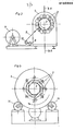
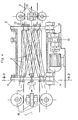
- FIGS. 1 to 5 Examples of possible embodiments of the device according to the invention are shown in FIGS. 1 to 5.
- FIGS. 1 to 5 mean the axis of rotational symmetry of the space serving for compression, which is enclosed by the rollers 2.
- 3 is the body to be compressed, 4 the ring-shaped frame on the input side of the device, 5 that on the output side. 6. represents the drive of the rollers 2, 7 is the roll of packaging material 9, which is fed to the body 3 via deflection rolls 8 and via the braking device 10.
- 11 is the transport device for removing the body 3, which is equipped with rollers 12 for absorbing the rotary movement, and 13 denotes the shaft stubs on the output side, which can be extended according to a variant of the device according to the invention.
- FIG. 1 is a longitudinal section through a device according to the invention at the point marked A - A in FIG. 2.
- Figure 2 is a cross section of the same device at the narrowest point of the tapered space. Its position is designated B - B in FIG. 1.
- the body 3 is drawn as if it were transparent.
- the annular frame 4 and 5 are rigidly arranged, that is, the body 3 must be freely rotatable. In this embodiment, it is not itself stored, but is instead replaced by a suitable, independent device which is not shown in FIG. B. by a mandrel that is mobile, in which he z. B.
- Figure 3 represents a section in the plane CC in Figure 1.
- the ring-shaped frames 4 and 5 are not shown adjustable in FIG. 1, so that a change in the angle alpha would not be possible in this embodiment.
- This embodiment was selected for the figure 1 for reasons of clarity.
- the devices which are necessary to make one of the frames 4 or 5 rotatable to such an extent that it allows a variation in the degree of compaction within the range according to the invention by setting any angle alpha, are familiar to any person skilled in the art.
- FIG. 4 and 5 represent an embodiment in which the body 3 can not perform a rotational movement, so that it is necessary to achieve the effect according to the invention that the annular frames 4 and 5 are rotatably mounted on two pairs of rollers 14. They must also be rigidly connected in order to be able to carry out a synchronous rotary movement in the same direction as the rotary movement of the individual rollers 2.
- 15 is the drive of the frames 4 and 5, 16 are the means for preventing the rotational movement of the body 3.
- FIG. 5 is a section at the point labeled D-D in FIG. 4.
Landscapes
- Engineering & Computer Science (AREA)
- Mechanical Engineering (AREA)
- Forging (AREA)
- Press Drives And Press Lines (AREA)
- Compressors, Vaccum Pumps And Other Relevant Systems (AREA)
- Massaging Devices (AREA)
- Rolls And Other Rotary Bodies (AREA)
- Basic Packing Technique (AREA)
- Auxiliary Devices For And Details Of Packaging Control (AREA)
- Treatment Of Fiber Materials (AREA)
Priority Applications (1)
| Application Number | Priority Date | Filing Date | Title |
|---|---|---|---|
| AT85102502T ATE29451T1 (de) | 1984-04-19 | 1985-03-06 | Verfahren und vorrichtung zur radialen verdichtung von zylindrischen koerpern aus komprimierbarem material. |
Applications Claiming Priority (2)
| Application Number | Priority Date | Filing Date | Title |
|---|---|---|---|
| DE19843415036 DE3415036A1 (de) | 1984-04-19 | 1984-04-19 | Verfahren und vorrichtung zur radialen verdichtung von zylindrischen koerpern aus komprimierbarem material |
| DE3415036 | 1984-04-19 |
Publications (2)
| Publication Number | Publication Date |
|---|---|
| EP0160802A1 true EP0160802A1 (fr) | 1985-11-13 |
| EP0160802B1 EP0160802B1 (fr) | 1987-09-09 |
Family
ID=6234121
Family Applications (1)
| Application Number | Title | Priority Date | Filing Date |
|---|---|---|---|
| EP85102502A Expired EP0160802B1 (fr) | 1984-04-19 | 1985-03-06 | Procédé et dispositif pour comprimer radialement des corps cylindriques en matériau compressible |
Country Status (9)
| Country | Link |
|---|---|
| US (1) | US4587895A (fr) |
| EP (1) | EP0160802B1 (fr) |
| JP (1) | JPS60240607A (fr) |
| AT (1) | ATE29451T1 (fr) |
| AU (1) | AU569947B2 (fr) |
| CA (1) | CA1244279A (fr) |
| DE (2) | DE3415036A1 (fr) |
| DK (1) | DK174785A (fr) |
| ZA (1) | ZA852911B (fr) |
Families Citing this family (5)
| Publication number | Priority date | Publication date | Assignee | Title |
|---|---|---|---|---|
| US5746378A (en) * | 1995-06-23 | 1998-05-05 | Marathon Equipment Company | Volume reduction machine |
| DE19629606C2 (de) * | 1996-07-23 | 2001-05-10 | Fillmatic Polsterindustriemasc | Vorrichtung zum Verpacken von mit einer Stoffhülle umgebenen Matratzen |
| ES2190822B1 (es) * | 1997-05-28 | 2004-10-16 | Flex Equipos De Descanso S.A. | Procedimiento de transformacion de bloques de espuma de poliuretano paralelepipedicos en bloques cilindricos, para su transporte. |
| AU2008100847A4 (en) * | 2007-10-12 | 2008-10-09 | Bluescope Steel Limited | Method of forming textured casting rolls with diamond engraving |
| CN115196119B (zh) * | 2021-04-13 | 2024-06-25 | 泉州市振鑫机械制造有限公司 | 一种压缩清洁产品全自动送料压缩装置及全自动生产线 |
Citations (2)
| Publication number | Priority date | Publication date | Assignee | Title |
|---|---|---|---|---|
| FR1597272A (fr) * | 1968-07-10 | 1970-06-22 | ||
| US3606725A (en) * | 1969-10-22 | 1971-09-21 | Hugh C Dugan | Method of and apparatus for compressing a volume of material to be packaged |
Family Cites Families (3)
| Publication number | Priority date | Publication date | Assignee | Title |
|---|---|---|---|---|
| US2974457A (en) * | 1959-06-22 | 1961-03-14 | James B Saxton | Machine for bundling and baling trees |
| US3445985A (en) * | 1966-11-21 | 1969-05-27 | Sam Manetta | Packaging device |
| JPS522687A (en) * | 1975-06-23 | 1977-01-10 | Nippon Sangyo Kikai Kk | Packaging device for elastic body |
-
1984
- 1984-04-19 DE DE19843415036 patent/DE3415036A1/de not_active Withdrawn
-
1985
- 1985-03-06 AT AT85102502T patent/ATE29451T1/de not_active IP Right Cessation
- 1985-03-06 DE DE8585102502T patent/DE3560566D1/de not_active Expired
- 1985-03-06 EP EP85102502A patent/EP0160802B1/fr not_active Expired
- 1985-03-19 US US06/713,741 patent/US4587895A/en not_active Expired - Fee Related
- 1985-03-21 CA CA000477150A patent/CA1244279A/fr not_active Expired
- 1985-04-18 DK DK174785A patent/DK174785A/da not_active Application Discontinuation
- 1985-04-18 AU AU41389/85A patent/AU569947B2/en not_active Ceased
- 1985-04-18 ZA ZA852911A patent/ZA852911B/xx unknown
- 1985-04-19 JP JP60082699A patent/JPS60240607A/ja active Pending
Patent Citations (2)
| Publication number | Priority date | Publication date | Assignee | Title |
|---|---|---|---|---|
| FR1597272A (fr) * | 1968-07-10 | 1970-06-22 | ||
| US3606725A (en) * | 1969-10-22 | 1971-09-21 | Hugh C Dugan | Method of and apparatus for compressing a volume of material to be packaged |
Also Published As
| Publication number | Publication date |
|---|---|
| ATE29451T1 (de) | 1987-09-15 |
| ZA852911B (en) | 1985-12-24 |
| EP0160802B1 (fr) | 1987-09-09 |
| AU4138985A (en) | 1985-10-24 |
| DE3415036A1 (de) | 1985-10-31 |
| DK174785A (da) | 1985-10-20 |
| CA1244279A (fr) | 1988-11-08 |
| AU569947B2 (en) | 1988-02-25 |
| US4587895A (en) | 1986-05-13 |
| DE3560566D1 (en) | 1987-10-15 |
| DK174785D0 (da) | 1985-04-18 |
| JPS60240607A (ja) | 1985-11-29 |
Similar Documents
| Publication | Publication Date | Title |
|---|---|---|
| EP0910486B1 (fr) | Procede et dispositif de pliage de profiles a postes modulaires multiples | |
| AT389713B (de) | Vorrichtung zum offenendspinnen von fasern | |
| CH689000A5 (de) | Verfahren zur Herstellung von Fuellk¦rpern fuer Verpackungszwecke. | |
| DE4418900A1 (de) | Wickelmaschine zum Aufwickeln einer laufenden Papierbahn | |
| EP0160802B1 (fr) | Procédé et dispositif pour comprimer radialement des corps cylindriques en matériau compressible | |
| DE3942044A1 (de) | Vorrichtung zum aufwickeln eines multifilaments mit flacher form und grosser breite | |
| DE2141972A1 (de) | Vorrichtung zum unterteilen eines drahtwindungsstranges in einer bundbildestation | |
| DE60009016T2 (de) | Vorrichtung zur mechanischen Reinigung von Draht für die Herstellung von gezogenen Metalldrähten | |
| AT382579B (de) | Verfahren und vorrichtung zur radialen verdichtung von zylindrischen koerpern aus komprimierbarem material | |
| DE3141039C2 (de) | Vorrichtung zum Bewegen stangenförmigen Gutes, wie z.B. Rohre, Wellen und Draht, in Richtung seiner Längsachse, insbesondere als Ein- oder Auszungseinrichtung für Schäl- und/oder Richtmaschinen | |
| DE4335580C2 (de) | Vorrichtung zum Trennen einer mehrfach hohen Dosenzarge | |
| DE2350746C3 (de) | Verfahren und Vorrichtungen zur Herstellung von Granulaten aus pulverformigem, körnigem oder teigigem Gut | |
| DE952520C (de) | Konischer Spaltsiebkorb, insbesondere fuer Schleudern, sowie Verfahren und Vorrichtung zu seiner Herstellung | |
| DE3834039A1 (de) | Querbandanordnung am ausgang einer karde | |
| EP0080519B1 (fr) | Procédé et machine pour plier des affiches | |
| DE4127761C1 (fr) | ||
| DE3126805A1 (de) | Walzwerk zur herstellung von endlosen spiralen | |
| DE3238388A1 (de) | Verfahren und vorrichtung zum breitstrecken eines teigband-rohstueckes | |
| EP0765610A1 (fr) | Dispositif pour rouler des cigarettes | |
| DE2550888C3 (de) | Vorrichtung zum Quetschen von Getreidekorn | |
| DE1602680B2 (de) | Schrägwalzvorrichtung zum Verformen des Querschnittes eines zylindrischen Metallstabes | |
| DE2638353A1 (de) | Vorrichtung zur vorformung von faservliesen | |
| DE19736102C2 (de) | Zweiwalzen-Biegemaschine | |
| EP0523536B1 (fr) | Méthode et appareil pour favoriser la cohésion d'un cordon pressé sortant d'une presse avec un mouvement axial | |
| DE8100961U1 (de) | Vorrichtung zur herstellung von bewickelten ringen |
Legal Events
| Date | Code | Title | Description |
|---|---|---|---|
| PUAI | Public reference made under article 153(3) epc to a published international application that has entered the european phase |
Free format text: ORIGINAL CODE: 0009012 |
|
| 17P | Request for examination filed |
Effective date: 19850306 |
|
| AK | Designated contracting states |
Designated state(s): AT BE CH DE FR GB IT LI LU NL SE |
|
| 17Q | First examination report despatched |
Effective date: 19861113 |
|
| GRAA | (expected) grant |
Free format text: ORIGINAL CODE: 0009210 |
|
| AK | Designated contracting states |
Kind code of ref document: B1 Designated state(s): AT BE CH DE FR GB IT LI LU NL SE |
|
| REF | Corresponds to: |
Ref document number: 29451 Country of ref document: AT Date of ref document: 19870915 Kind code of ref document: T |
|
| ITF | It: translation for a ep patent filed | ||
| REF | Corresponds to: |
Ref document number: 3560566 Country of ref document: DE Date of ref document: 19871015 |
|
| GBT | Gb: translation of ep patent filed (gb section 77(6)(a)/1977) | ||
| ET | Fr: translation filed | ||
| PG25 | Lapsed in a contracting state [announced via postgrant information from national office to epo] |
Ref country code: LU Free format text: LAPSE BECAUSE OF NON-PAYMENT OF DUE FEES Effective date: 19880331 |
|
| PLBE | No opposition filed within time limit |
Free format text: ORIGINAL CODE: 0009261 |
|
| STAA | Information on the status of an ep patent application or granted ep patent |
Free format text: STATUS: NO OPPOSITION FILED WITHIN TIME LIMIT |
|
| 26N | No opposition filed | ||
| PGFP | Annual fee paid to national office [announced via postgrant information from national office to epo] |
Ref country code: FR Payment date: 19890222 Year of fee payment: 5 |
|
| PGFP | Annual fee paid to national office [announced via postgrant information from national office to epo] |
Ref country code: SE Payment date: 19890224 Year of fee payment: 5 Ref country code: DE Payment date: 19890224 Year of fee payment: 5 Ref country code: CH Payment date: 19890224 Year of fee payment: 5 |
|
| PGFP | Annual fee paid to national office [announced via postgrant information from national office to epo] |
Ref country code: LU Payment date: 19890227 Year of fee payment: 5 |
|
| PGFP | Annual fee paid to national office [announced via postgrant information from national office to epo] |
Ref country code: AT Payment date: 19890302 Year of fee payment: 5 |
|
| PGFP | Annual fee paid to national office [announced via postgrant information from national office to epo] |
Ref country code: BE Payment date: 19890323 Year of fee payment: 5 |
|
| ITTA | It: last paid annual fee | ||
| PGFP | Annual fee paid to national office [announced via postgrant information from national office to epo] |
Ref country code: NL Payment date: 19890331 Year of fee payment: 5 Ref country code: GB Payment date: 19890331 Year of fee payment: 5 |
|
| PG25 | Lapsed in a contracting state [announced via postgrant information from national office to epo] |
Ref country code: GB Effective date: 19900306 Ref country code: AT Effective date: 19900306 |
|
| PG25 | Lapsed in a contracting state [announced via postgrant information from national office to epo] |
Ref country code: SE Effective date: 19900307 |
|
| PG25 | Lapsed in a contracting state [announced via postgrant information from national office to epo] |
Ref country code: LI Effective date: 19900331 Ref country code: CH Effective date: 19900331 Ref country code: BE Effective date: 19900331 |
|
| BERE | Be: lapsed |
Owner name: CHEMIE LINZ A.G. Effective date: 19900331 |
|
| PG25 | Lapsed in a contracting state [announced via postgrant information from national office to epo] |
Ref country code: NL Effective date: 19901001 |
|
| GBPC | Gb: european patent ceased through non-payment of renewal fee | ||
| NLV4 | Nl: lapsed or anulled due to non-payment of the annual fee | ||
| PG25 | Lapsed in a contracting state [announced via postgrant information from national office to epo] |
Ref country code: FR Effective date: 19901130 |
|
| REG | Reference to a national code |
Ref country code: CH Ref legal event code: PL |
|
| PG25 | Lapsed in a contracting state [announced via postgrant information from national office to epo] |
Ref country code: DE Effective date: 19901201 |
|
| REG | Reference to a national code |
Ref country code: FR Ref legal event code: ST |
|
| EUG | Se: european patent has lapsed |
Ref document number: 85102502.3 Effective date: 19910110 |