EP0160835A1 - Procédé et dispositif pour la coulée continue de métal dans une lingotière à parois refroidies animées d'un mouvement circulaire - Google Patents
Procédé et dispositif pour la coulée continue de métal dans une lingotière à parois refroidies animées d'un mouvement circulaire Download PDFInfo
- Publication number
- EP0160835A1 EP0160835A1 EP85103986A EP85103986A EP0160835A1 EP 0160835 A1 EP0160835 A1 EP 0160835A1 EP 85103986 A EP85103986 A EP 85103986A EP 85103986 A EP85103986 A EP 85103986A EP 0160835 A1 EP0160835 A1 EP 0160835A1
- Authority
- EP
- European Patent Office
- Prior art keywords
- cooled
- mold cavity
- metal
- walls
- casting
- Prior art date
- Legal status (The legal status is an assumption and is not a legal conclusion. Google has not performed a legal analysis and makes no representation as to the accuracy of the status listed.)
- Granted
Links
Images

Classifications
-
- B—PERFORMING OPERATIONS; TRANSPORTING
- B22—CASTING; POWDER METALLURGY
- B22D—CASTING OF METALS; CASTING OF OTHER SUBSTANCES BY THE SAME PROCESSES OR DEVICES
- B22D11/00—Continuous casting of metals, i.e. casting in indefinite lengths
- B22D11/06—Continuous casting of metals, i.e. casting in indefinite lengths into moulds with travelling walls, e.g. with rolls, plates, belts, caterpillars
- B22D11/0637—Accessories therefor
- B22D11/064—Accessories therefor for supplying molten metal
Definitions
- the invention relates to a process for the continuous casting of metal, in particular steel, in the form of strips or thin slabs, the molten metal being poured between four cooled walls moving in the casting direction using a feed device and a casting drum jacket cools the first broad side of the band forming in the mold cavity, a second cooled wall cools the other broad side of the band forming and two narrow side walls are provided which move with the first or second cooled wall and which cool the narrow sides of the substantially rectangular band which forms and where one of the two broad side walls engages between the narrow side walls, and on a device for carrying out the method.
- a method for the continuous casting of essentially rectangular steel strips is known.
- the molten metal is poured between two rotating casting drums using a ceramic feed device.
- a first casting drum is provided with a recess on its outer surface and forms a broad side and two narrow sides of the mold cavity.
- the second casting drum which engages along the length of the mold cavity between the narrow sides of the first casting drum, results in the second broad side of the mold cavity.
- These springs are connected to the strand skin of the broad side of the band which is formed at the same time. They prevent the drum from shrinking or becoming detached due to the cooling of the broadside. This leads to strand defects, in particular to cracks or breakthroughs, which lead to the casting being stopped immediately.
- the invention has for its object to prevent the shortcomings shown in strip casting systems with high throughput according to the preamble.
- the formation of eyebrows and feathers protruding parallel to the narrow sides over the broad side is to be prevented, thereby avoiding cracks in the strand material, breakthroughs and other casting errors.
- the cast metal is strongly cooled before reaching the contact surface on the narrow side in the gap between the drum engaging on a broad side and the extension of the feed device, and a thin metal layer solidifies continuously.
- the further metal supply for filling the gap gradually expanding towards the narrow side along the uncooled extension of the ceramic metal supply device is maintained.
- the flowing metal gives some of its heat to the layer that has already solidified Drum, whereby on the one hand the already solidified layer continues to grow, on the other hand the toughness of the metal running along it increases. This prevents liquid metal from penetrating the gap between the engaging drum shell and the narrow side flanks.
- the broad side crust has solidified up to the narrow side wall, it increases in thickness and the solidification of a crust also begins from the narrow side wall which has already been cooled there. There is therefore no longer any risk of burrs or feathers forming.
- the contact area and the corresponding gap opening in the casting direction can be enlarged after an additional identifier.
- a control of the solidification of the narrow sides of the strip or a thin slab in the mold cavity is achieved according to an additional feature if, after the metal flows into the mold cavity, contact between the cooled narrow sides of the mold cavity and the cast metal is initially prevented over a first partial length of the mold cavity , is granted on a second partial length on a contact surface which corresponds to only a fraction of the respective distance between the two broad-side cooling walls and is granted on a third partial length on a contact surface which corresponds to the full distance between the two broad-side cooling walls in the mold cavity.
- a corresponding device for carrying out this method describes the features of claim 6. With this method and with this device, the strand quality on the narrow sides can be improved and the wear on the drums can be reduced.
- the dimensioning of both the gap opening and the flow length of the metal in the gap itself is the Giessge speed, the casting format, the casting metal and the cooling capacity of the cooling wall. According to another characteristic, a gap opening of 1/2 to 1/12 of the respective cooling wall distance on the broad sides is recommended as the mean value.
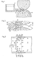
- a continuous casting plant for strips and thin slabs with mold walls moved in a circuit which essentially consists of two casting drums 2 and 3 and a feed device 4.
- a cooling wall in the form of a band which is moved in a circuit could also be used.
- Molten metal is fed from a container 5 in the casting direction 6 between the drums 2, 3. Cooled walls 7, 8, 9 of the drums 2, 3 form the mold in the mold cavity 10.
- a chain 12, indicated by dash-dotted lines, can be continued, cooled and, if necessary, continued straight after the exit from the narrowest gap 14, which also represents the end of the mold cavity 10, in a straight line or curved manner, as shown in FIG.
- the drums 2 and 3 are only hinted at and the feed device 4 is only partially shown.
- the drum 2 forms for example a first 7, the drum 3 a second cooled broad side wall 8 and the narrow side walls 9, 9 '.
- the mold cavity 10 begins at the surface 20 of the feed device 4 and ends at the dash-dotted line 21, which coincides with the thinnest gap between the drums 2 and 3.
- the mold cavity 10 is delimited on the side first by extensions 23, 23 'of the feed device 4 arranged on both sides and then by the cooled narrow side walls 9, 9'.
- the drum 2 engages over a partial length 24 of the mold cavity length 25 between the narrow side walls 9, 9 '.
- the broad side walls 7 and 8 first cool the two broad sides of the strand that forms on a partial width 26.
- contact of the liquid metal with the cooled side flanks 9, 9 'of the drum 3 is initially granted only along a contact surface 27 which corresponds to only a fraction of the respective distance between the two broad side walls 7, 8.
- the metal is specifically cooled before reaching the contact surface 27 in a gap between the extensions 23, 23 'of the feed device 4 and the wall 7 of the drum 2.
- the cross section of the gap opening 11 (FIGS. 5, 6), which results from shoulders 31 on the extensions 23, 23 ', corresponds essentially to the contact surface 27.
- the contact surface 27 and the corresponding gap opening 11 increase in the casting direction 6.
- the gap opening 11 is usually 1/12 - 1/2 of the respective cooling wall distance between the broad sides, depending on the strip thickness and casting speed.
- the mold cavity 10 is divided into three partial lengths 33, 34, 35. After the metal flows in from a feed channel 32 In the mold cavity 10, contact between the cooled narrow side wall 9 and the cast metal is prevented over the first partial length 33.
- the metal flows through the gap opening 11 against the contact surface 27.
- the gap opening 11 or the shoulder 31 is advantageously enlarged towards the feed channel.
- the boundary edge 39 forms an angle ⁇ of, for example, 45 ° with the casting direction 6.
- contact between the cast metal and the cooled narrow sides 9 is granted on a surface which corresponds to the full distance between the two broad side walls in the mold cavity.
- the premature solidification of the casting metal in the gap opening along the broad side wall 7 prevents penetration of liquid metal into gap joints 40 (FIGS. 6, 7) parallel to the narrow side, in which springs or burrs could otherwise form, which lead to the disadvantages mentioned.
- the casting direction is shown horizontally in the examples. However, any other casting direction can be used, in particular it is advantageous to pour obliquely upwards.
Landscapes
- Engineering & Computer Science (AREA)
- Mechanical Engineering (AREA)
- Continuous Casting (AREA)
Applications Claiming Priority (2)
| Application Number | Priority Date | Filing Date | Title |
|---|---|---|---|
| CH1738/84 | 1984-04-06 | ||
| CH1738/84A CH665370A5 (de) | 1984-04-06 | 1984-04-06 | Verfahren und vorrichtung zum kontinuierlichen giessen von metall in einen formhohlraum mit im kreislauf sich bewegenden gekuehlten waenden. |
Publications (2)
| Publication Number | Publication Date |
|---|---|
| EP0160835A1 true EP0160835A1 (fr) | 1985-11-13 |
| EP0160835B1 EP0160835B1 (fr) | 1987-12-09 |
Family
ID=4217425
Family Applications (1)
| Application Number | Title | Priority Date | Filing Date |
|---|---|---|---|
| EP85103986A Expired EP0160835B1 (fr) | 1984-04-06 | 1985-04-02 | Procédé et dispositif pour la coulée continue de métal dans une lingotière à parois refroidies animées d'un mouvement circulaire |
Country Status (10)
| Country | Link |
|---|---|
| US (1) | US4582119A (fr) |
| EP (1) | EP0160835B1 (fr) |
| JP (1) | JPH0677790B2 (fr) |
| AU (1) | AU585218B2 (fr) |
| BR (1) | BR8501596A (fr) |
| CA (1) | CA1228969A (fr) |
| CH (1) | CH665370A5 (fr) |
| DE (1) | DE3561133D1 (fr) |
| IN (1) | IN163513B (fr) |
| ZA (1) | ZA852474B (fr) |
Cited By (1)
| Publication number | Priority date | Publication date | Assignee | Title |
|---|---|---|---|---|
| GB2198976A (en) * | 1986-12-19 | 1988-06-29 | Davy Mckeen | Twin roll metal casting apparatus |
Families Citing this family (1)
| Publication number | Priority date | Publication date | Assignee | Title |
|---|---|---|---|---|
| CH664916A5 (de) * | 1984-04-18 | 1988-04-15 | Concast Service Union Ag | Vorrichtung zum seitlichen abschliessen eines formhohlraumes mit im wesentlichen rechteckigem querschnitt in einer stranggiessanlage. |
Citations (3)
| Publication number | Priority date | Publication date | Assignee | Title |
|---|---|---|---|---|
| FR2091851A1 (fr) * | 1969-12-26 | 1971-01-21 | Namy Philippe | |
| DE2926181A1 (de) * | 1978-06-29 | 1980-01-03 | Hitachi Ltd | Stranggiessvorrichtung |
| DE3207010A1 (de) * | 1981-02-27 | 1982-10-14 | Hitachi, Ltd., Tokyo | Metallblech-durchlaufgiesseinrichtung |
Family Cites Families (4)
| Publication number | Priority date | Publication date | Assignee | Title |
|---|---|---|---|---|
| US3730254A (en) * | 1970-12-18 | 1973-05-01 | Creusot Loire | Roller pair type continuous casting apparatus |
| US3964963A (en) * | 1972-12-27 | 1976-06-22 | Martin Marietta Aluminum Inc. | Apparatus for producing continuous cast metallic sheet with patterned surface |
| JPS6035220B2 (ja) * | 1981-01-19 | 1985-08-13 | 日本鋼管株式会社 | 薄板製造方法及びその装置 |
| CH666842A5 (de) * | 1984-03-01 | 1988-08-31 | Concast Service Union Ag | Verfahren und vorrichtung zum kontinuierlichen giessen von metallen in form von band zwischen zwei gekuehlten achsparallelen trommeln. |
-
1984
- 1984-04-06 CH CH1738/84A patent/CH665370A5/de not_active IP Right Cessation
-
1985
- 1985-03-25 US US06/715,987 patent/US4582119A/en not_active Expired - Lifetime
- 1985-03-30 IN IN239/CAL/85A patent/IN163513B/en unknown
- 1985-04-01 AU AU40579/85A patent/AU585218B2/en not_active Ceased
- 1985-04-02 EP EP85103986A patent/EP0160835B1/fr not_active Expired
- 1985-04-02 CA CA000478160A patent/CA1228969A/fr not_active Expired
- 1985-04-02 ZA ZA852474A patent/ZA852474B/xx unknown
- 1985-04-02 DE DE8585103986T patent/DE3561133D1/de not_active Expired
- 1985-04-03 BR BR8501596A patent/BR8501596A/pt not_active IP Right Cessation
- 1985-04-05 JP JP60071276A patent/JPH0677790B2/ja not_active Expired - Lifetime
Patent Citations (3)
| Publication number | Priority date | Publication date | Assignee | Title |
|---|---|---|---|---|
| FR2091851A1 (fr) * | 1969-12-26 | 1971-01-21 | Namy Philippe | |
| DE2926181A1 (de) * | 1978-06-29 | 1980-01-03 | Hitachi Ltd | Stranggiessvorrichtung |
| DE3207010A1 (de) * | 1981-02-27 | 1982-10-14 | Hitachi, Ltd., Tokyo | Metallblech-durchlaufgiesseinrichtung |
Non-Patent Citations (1)
| Title |
|---|
| PATENT ABSTRACTS OF JAPAN, vol. 6, no. 236, 25. November 1982, Seite (M-173) (1114); & JP-A-57-137056 (HITACHI) 24-08-1982 * |
Cited By (2)
| Publication number | Priority date | Publication date | Assignee | Title |
|---|---|---|---|---|
| GB2198976A (en) * | 1986-12-19 | 1988-06-29 | Davy Mckeen | Twin roll metal casting apparatus |
| GB2198976B (en) * | 1986-12-19 | 1990-10-17 | Davy Mckeen | Roll caster |
Also Published As
| Publication number | Publication date |
|---|---|
| DE3561133D1 (en) | 1988-01-21 |
| IN163513B (fr) | 1988-10-01 |
| BR8501596A (pt) | 1985-12-03 |
| CA1228969A (fr) | 1987-11-10 |
| JPS60231557A (ja) | 1985-11-18 |
| AU4057985A (en) | 1985-10-10 |
| EP0160835B1 (fr) | 1987-12-09 |
| US4582119A (en) | 1986-04-15 |
| ZA852474B (en) | 1985-11-27 |
| CH665370A5 (de) | 1988-05-13 |
| JPH0677790B2 (ja) | 1994-10-05 |
| AU585218B2 (en) | 1989-06-15 |
Similar Documents
| Publication | Publication Date | Title |
|---|---|---|
| EP0149734B1 (fr) | Lingotière pour la coulée continue d'un ruban d'acier | |
| DE3855653T2 (de) | Vorrichtung und Verfahren zum direkten Giessen von Metallband | |
| DE69615176T2 (de) | Giessen von stahlbändern | |
| DE10042078A1 (de) | Verfahren und Vorrichtung zum kontinuierlichen Gießen von Stahlband aus Stahlschmelze | |
| EP2025432A1 (fr) | Procédé destiné à la production de produits allongés en acier par coulage en continu et laminage | |
| DE1771762C3 (de) | Vorrichtung zur kontinuierlichen Herstellung von Flachglas | |
| DE60000858T2 (de) | Verfahren und vorrichtung zum stranggiessen mit hoher geschwindigkeit | |
| EP3993921B1 (fr) | Alimentation de matière en fusion pour installations de coulée à bande | |
| LU85485A1 (de) | Vorrichtung und verfahren zum kontinuierlichen giessen von metall | |
| DE2548939C2 (de) | Verfahren und Vorrichtung zum Stranggießen von Bändern | |
| DE2853867C2 (de) | Verfahren zum Vermeiden von Rissen im Kantenbereich von in einer Stranggießkokille gegossenen Metallsträngen sowie Zusatzstoff und Vorrichtung zur Durchführung des Verfahrens | |
| DE69213160T2 (de) | Gebogene Kokille zum Bogenstranggiessen von dünnen Brammen | |
| EP0160835B1 (fr) | Procédé et dispositif pour la coulée continue de métal dans une lingotière à parois refroidies animées d'un mouvement circulaire | |
| DE2853868C2 (de) | Verfahren zum Stranggießen von Stahl sowie dementsprechend hergestellter Stahlstrang | |
| DE2913024A1 (de) | Verfahren zum kuehlen einer oszillierenden stahl-stranggiesskokille | |
| EP0325792A2 (fr) | Procédé pour la coulée d'une bande d'acier dans une installation de coulée pour bandes d'acier | |
| DE3029223C2 (de) | Einlauf für die Metallschmelze in Stranggießvorrichtungen | |
| EP0154250A2 (fr) | Procédé et dispositif pour la coulée continue des métaux entre deux tambours refroidis à axes parallèles | |
| EP0107069A1 (fr) | Procédé pour la coulée continue de métaux, en particulier de l'acier et installations de coulée continue pour la mise en oeuvre du procédé | |
| EP0161475B1 (fr) | Dispositif pour la fermeture latérale d'une cavité de façonnage avec une coupe transversale substantiellement rectangulaire dans une installation de coulée continue | |
| DE4006842A1 (de) | Bandgiessanlage mit oszillierender durchlaufkokille | |
| DE69000282T2 (de) | Verfahren und vorrichtung zur herstellung von duennen metallprodukten mittels strangguss. | |
| EP1827735B1 (fr) | Procede et dispositif de coulee en bande de metaux | |
| DE4406012C2 (de) | Vorrichtung zum Angießen einer Stranggießanlage | |
| DE3028247A1 (de) | Vorrichtung zur erzeugung von eisen-ausgangsmaterialien |
Legal Events
| Date | Code | Title | Description |
|---|---|---|---|
| PUAI | Public reference made under article 153(3) epc to a published international application that has entered the european phase |
Free format text: ORIGINAL CODE: 0009012 |
|
| AK | Designated contracting states |
Designated state(s): DE FR GB IT |
|
| 17P | Request for examination filed |
Effective date: 19860403 |
|
| 17Q | First examination report despatched |
Effective date: 19860929 |
|
| ITF | It: translation for a ep patent filed | ||
| GRAA | (expected) grant |
Free format text: ORIGINAL CODE: 0009210 |
|
| AK | Designated contracting states |
Kind code of ref document: B1 Designated state(s): DE FR GB IT |
|
| ET | Fr: translation filed | ||
| REF | Corresponds to: |
Ref document number: 3561133 Country of ref document: DE Date of ref document: 19880121 |
|
| GBT | Gb: translation of ep patent filed (gb section 77(6)(a)/1977) | ||
| PLBE | No opposition filed within time limit |
Free format text: ORIGINAL CODE: 0009261 |
|
| STAA | Information on the status of an ep patent application or granted ep patent |
Free format text: STATUS: NO OPPOSITION FILED WITHIN TIME LIMIT |
|
| 26N | No opposition filed | ||
| ITPR | It: changes in ownership of a european patent |
Owner name: CESSIONE;CLECIM, DAVY (DISTINGTON) LIMITED |
|
| REG | Reference to a national code |
Ref country code: GB Ref legal event code: 732 |
|
| REG | Reference to a national code |
Ref country code: FR Ref legal event code: TP |
|
| ITTA | It: last paid annual fee | ||
| PGFP | Annual fee paid to national office [announced via postgrant information from national office to epo] |
Ref country code: FR Payment date: 19980312 Year of fee payment: 14 |
|
| PGFP | Annual fee paid to national office [announced via postgrant information from national office to epo] |
Ref country code: GB Payment date: 19980320 Year of fee payment: 14 |
|
| PGFP | Annual fee paid to national office [announced via postgrant information from national office to epo] |
Ref country code: DE Payment date: 19980325 Year of fee payment: 14 |
|
| PG25 | Lapsed in a contracting state [announced via postgrant information from national office to epo] |
Ref country code: GB Free format text: LAPSE BECAUSE OF NON-PAYMENT OF DUE FEES Effective date: 19990402 |
|
| GBPC | Gb: european patent ceased through non-payment of renewal fee |
Effective date: 19990402 |
|
| PG25 | Lapsed in a contracting state [announced via postgrant information from national office to epo] |
Ref country code: FR Free format text: LAPSE BECAUSE OF NON-PAYMENT OF DUE FEES Effective date: 19991231 |
|
| REG | Reference to a national code |
Ref country code: FR Ref legal event code: ST |
|
| PG25 | Lapsed in a contracting state [announced via postgrant information from national office to epo] |
Ref country code: DE Free format text: LAPSE BECAUSE OF NON-PAYMENT OF DUE FEES Effective date: 20000201 |