EP0160918A2 - Dispositif de fixation d'une unité d'éclairage sur la carrosserie d'un véhicule - Google Patents
Dispositif de fixation d'une unité d'éclairage sur la carrosserie d'un véhicule Download PDFInfo
- Publication number
- EP0160918A2 EP0160918A2 EP85105236A EP85105236A EP0160918A2 EP 0160918 A2 EP0160918 A2 EP 0160918A2 EP 85105236 A EP85105236 A EP 85105236A EP 85105236 A EP85105236 A EP 85105236A EP 0160918 A2 EP0160918 A2 EP 0160918A2
- Authority
- EP
- European Patent Office
- Prior art keywords
- lighting unit
- cavities
- plastic
- housing
- motor vehicle
- Prior art date
- Legal status (The legal status is an assumption and is not a legal conclusion. Google has not performed a legal analysis and makes no representation as to the accuracy of the status listed.)
- Withdrawn
Links
Images

Classifications
-
- B—PERFORMING OPERATIONS; TRANSPORTING
- B60—VEHICLES IN GENERAL
- B60Q—ARRANGEMENT OF SIGNALLING OR LIGHTING DEVICES, THE MOUNTING OR SUPPORTING THEREOF OR CIRCUITS THEREFOR, FOR VEHICLES IN GENERAL
- B60Q1/00—Arrangement of optical signalling or lighting devices, the mounting or supporting thereof or circuits therefor
- B60Q1/02—Arrangement of optical signalling or lighting devices, the mounting or supporting thereof or circuits therefor the devices being primarily intended to illuminate the way ahead or to illuminate other areas of way or environments
- B60Q1/04—Arrangement of optical signalling or lighting devices, the mounting or supporting thereof or circuits therefor the devices being primarily intended to illuminate the way ahead or to illuminate other areas of way or environments the devices being headlights
- B60Q1/0408—Arrangement of optical signalling or lighting devices, the mounting or supporting thereof or circuits therefor the devices being primarily intended to illuminate the way ahead or to illuminate other areas of way or environments the devices being headlights built into the vehicle body, e.g. details concerning the mounting of the headlamps on the vehicle body
- B60Q1/0441—Arrangement of optical signalling or lighting devices, the mounting or supporting thereof or circuits therefor the devices being primarily intended to illuminate the way ahead or to illuminate other areas of way or environments the devices being headlights built into the vehicle body, e.g. details concerning the mounting of the headlamps on the vehicle body the housing being fastened onto the vehicle body using means other than screws
Definitions
- the invention relates to a device for fastening a lighting unit to a motor vehicle body, the housing of the lighting unit being connected to the body directly or via a support frame.
- body includes body parts, such as front and rear sections, where the lighting is doing g sgnac to install and are attached to the rest of the body. These body parts can be made of sheet metal, but are increasingly also made of plastic (eg "soft nose") in order to survive minor accidents without permanent deformation.
- Headlights have so far only been attached to the body by means of screws with washers and nuts, and additionally by spring clips in order to achieve elastic absorption of the headlights within certain limits and in particular to dampen road bumps, which considerably shorten the life of the light bulbs.
- This type of assembly is relatively complex and, above all, can hardly be carried out fully automatically.
- the screws, washers and nuts are loose parts, some of which is lost during assembly.
- the invention has for its object to provide a device for fastening a lighting device to a motor vehicle body, with which the fastening can be fully automated, which is inexpensive, no loose parts, such as screws, nuts and washers, allows a large tolerance compensation in every direction and causes road bumps to be transmitted to the lighting device only in a damped manner, without producing "dancing" light.
- the lighting unit When the lighting unit is mounted, its housing or the support frame is aligned and fixed in the body by conventional means, the anchoring projections attached to one part protruding into the undercut cavities on the other part. Then plastic is injected fully automatically into the cavities using conventional plastic spray guns, which after curing has a certain elasticity which can be adjusted.
- a foam plastic such as is also used, for example, when foaming window frames, has proven particularly advantageous. Since there can be a relatively large distance between the wall of the cavity and the anchoring protrusion protruding into it, which is made of the plastic manufacturing tolerances, which can be up to 10 mm for car bodies, can be easily compensated for. In the event of a repair, this connection can be released in a simple manner by melting the plastic using a thermal probe.
- the cavities are preferably formed by cup-like depressions, on the inner circumferential wall of which protrusions protrude radially inwards, preferably in the form of a radially inwardly extending rib.
- the cavities can also have a trapezoidal cross section.
- the anchoring projections are preferably cup-shaped and their bottom has a central opening. This design allows the production of these projections in a particularly simple manner if the part in question is a sheet metal part, since the projections are then simply pushed out of the sheet metal part. Of course, these projections can also be manufactured as separate sheet metal pressed parts, which are then welded to the relevant points on the body.
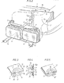
- FIG. 1 shows the front end of a motor vehicle body 1, which has cutouts 2 and 3 for accommodating one lighting unit each.
- the right lighting unit 4 is designed as a support frame double headlight and the left lighting unit 5 as a housing headlight.
- the lighting unit 4 has two built-in headlights 6, which is arranged in an adjustable manner in a support frame 7, which is fastened in the cutout 2 to the body 1.
- the Beleuchtun g sgnac 5 of the reflector is arranged together with the light bulb set in a housing 8 which is attached to the body 1 in the cutout.
- the arrangement and installation of the support frame double headlight 4 in the body cutout 2 is shown in Fig. 2 on a larger scale.
- the support frame 7 has upper extensions 9 and lower extensions 10, to which the frame 7 is fastened in the cutout 2 to the body 1.
- the attachment points on the body for the extensions 9 are designated 11 and the attachment points for the extensions 10 are designated 12.
- the extension 9 is provided with a cavity 13 with a circular cross section, on the inner circumferential wall of which a radially inwardly extending rib 14 is formed, so that an undercut cavity is formed.
- a pot-like projection 16 is pressed out of the body panel 15, the bottom 17 of which has a central opening 18 and engages in the cavity 13.
- the projection 16 is surrounded by an annular bead 19 on which the top of the extension 9 rests.
- the cavity 13 and the interior of the protrusion 16 are filled with a hardening elastic plastic 20, for example polyurethane foam, so that the protrusion 16 is embedded in the plastic.
- a hardening elastic plastic for example polyurethane foam
- the undercuts which are formed on the one hand by the rib 14 and on the other hand by the edge of the base 17, create a positive, but somewhat elastic connection between the extension 9 and the body panel 15 via the plastic 20.
- the attachment of the extensions 10 of the support frame 7 at the points 12 of the body can be done in the manner shown in FIG. 4.
- the fastening principle is the same as in FIG. 3, only here a pot-like body 21 is welded to the body panel 15a, the bottom 22 of which has a central opening 23 and which is provided with an annular bead 24 against which the extension 10 rests with its rear side .
- the extension 10 is provided with a cavity 25, similar to the exemplary embodiment according to FIG. 3, into which a rib 27 projects and the bottom 28 of which has an opening 29.
- the cavity 25 and also the interior of the pot-like body 21 is filled with hardening elastic plastic 26, which due to the undercuts formed by the rib 27 in the cavity 25 and the edge of the bottom 22 of the pot like body 21, a positive, but elastic connection between the extension 10 and the body panel 15a.
- the lighting unit 4 When the lighting unit 4 is assembled, it is fixed in position by means of an assembly guide in the cutout 2 of the body 1, the pot-like projections 16 coming to rest in the cavities 13 and the pot-like bodies 21 in the cavities 25. Then, by means of a spray gun, plastic is injected through the projections 16 unc through the openings 18 into the cavities 13 and through the openings 29 into the cavities 25 and through the openings 23 into the interior of the pot-like body 21 until it is completely filled with plastic are, as can be seen from Figures 3 and 4. After the plastic has hardened, the support frame 7 is fixed to the headlights 6, but is elastically connected to the body 1. Then the assembly aid gauge can be removed.
- the embodiment according to FIG. 5 largely corresponds to the embodiment according to FIG. 3, with the difference that the cavity 13 'has a trapezoidal cross section and is thereby undercut, so that the rib 14 from FIG. 3 can be omitted.
- the support frame 7 is made of plastic and the body part made of sheet metal.
- both parts can also consist of the same material or the body part made of plastic and the supporting frame made of sheet metal.
- the lighting unit 5 that is to say a housing headlight
- the headlight housing 8 is provided with undercut cavities 13 and 25, in which the pot-like projections 16 and 21 engage. Which of the versions of FIGS. 3 and 4 is used depends on the accessibility for the spray guns.
Landscapes
- Engineering & Computer Science (AREA)
- Mechanical Engineering (AREA)
- Lighting Device Outwards From Vehicle And Optical Signal (AREA)
- Non-Portable Lighting Devices Or Systems Thereof (AREA)
Applications Claiming Priority (2)
| Application Number | Priority Date | Filing Date | Title |
|---|---|---|---|
| DE3417041 | 1984-05-09 | ||
| DE3417041A DE3417041C2 (de) | 1984-05-09 | 1984-05-09 | Einrichtung zur Befestigung einer Beleuchtungseinheit an einer Kraftfahrzeugkarosserie |
Publications (2)
| Publication Number | Publication Date |
|---|---|
| EP0160918A2 true EP0160918A2 (fr) | 1985-11-13 |
| EP0160918A3 EP0160918A3 (fr) | 1987-12-09 |
Family
ID=6235284
Family Applications (1)
| Application Number | Title | Priority Date | Filing Date |
|---|---|---|---|
| EP85105236A Withdrawn EP0160918A3 (fr) | 1984-05-09 | 1985-04-30 | Dispositif de fixation d'une unité d'éclairage sur la carrosserie d'un véhicule |
Country Status (4)
| Country | Link |
|---|---|
| US (1) | US4636921A (fr) |
| EP (1) | EP0160918A3 (fr) |
| JP (1) | JPS616041A (fr) |
| DE (1) | DE3417041C2 (fr) |
Cited By (7)
| Publication number | Priority date | Publication date | Assignee | Title |
|---|---|---|---|---|
| FR2710592A1 (fr) * | 1993-09-30 | 1995-04-07 | Peugeot | Projecteur pour véhicule automobile équipé de butées élastiques. |
| FR2719359A1 (fr) * | 1994-04-28 | 1995-11-03 | Hella Kg Hueck & Co | Pièce de fermeture d'un carter d'un bloc optique pour véhicules, renfermant des réflecteurs. |
| EP0679552A3 (fr) * | 1994-04-28 | 1996-05-15 | Hella Kg Hueck & Co | Couvercle pour unité d'éclairage avec réflecteurs. |
| EP0679551A3 (fr) * | 1994-04-28 | 1996-05-22 | Hella Kg Hueck & Co | Unité d'éclairage pour véhicule. |
| WO2004065171A1 (fr) * | 2003-01-21 | 2004-08-05 | Schefenacker Vision Systems | Dispositif de fixation pour des elements, de preference des feux, de vehicules automobiles |
| FR3015003A1 (fr) * | 2013-12-13 | 2015-06-19 | Peugeot Citroen Automobiles Sa | Projecteur de vehicule automobile sans glace |
| FR3026688A1 (fr) * | 2014-10-06 | 2016-04-08 | Peugeot Citroen Automobiles Sa | Projecteur de vehicule sans glace |
Families Citing this family (10)
| Publication number | Priority date | Publication date | Assignee | Title |
|---|---|---|---|---|
| DE3542457A1 (de) * | 1985-11-30 | 1987-06-04 | Bosch Gmbh Robert | Scheinwerfer fuer fahrzeuge, insbesondere fuer kraftfahrzeuge |
| SE9604293D0 (sv) * | 1996-11-22 | 1996-11-22 | Lennart Gaelliner | Strålkastararrangemang |
| US6257749B1 (en) * | 1999-05-12 | 2001-07-10 | Honda Giken Kogyo Kabushiki Kaisha | Vehicle lamp housing having multiple mounting means, and method of using same |
| DE10309087A1 (de) * | 2003-03-03 | 2004-09-23 | Hella Kg Hueck & Co. | Befestigungseinrichtung für Kraftfahrzeug-Scheinwerfer |
| DE10314091A1 (de) * | 2003-03-28 | 2004-10-14 | Adam Opel Ag | Scheinwerfergehäuse und Fahrzeugkarosserie mit einer Aufnahme hierfür |
| JP3843968B2 (ja) * | 2003-06-24 | 2006-11-08 | 日産自動車株式会社 | ヘッドランプの車体位置決め方法および車体位置決め構造 |
| KR100514480B1 (ko) * | 2003-09-01 | 2005-09-14 | 기아자동차주식회사 | 자동차용 헤드램프와 휀더간의 간극 유지 구조 |
| DE102005009915B4 (de) * | 2005-03-01 | 2008-08-28 | Daimler Ag | Bugbereich eines Kraftwagens |
| DE102013008908A1 (de) * | 2013-05-25 | 2014-11-27 | Audi Ag | Kraftfahrzeugleuchte, Kraftfahrzeugscheinwerfer sowie System aus Kraftfahrzeugleuchte oder Kraftfahrzeugscheinwerfer und Bauteil für ein Kraftfahrzeug |
| DE102018129034B4 (de) | 2018-11-19 | 2022-03-17 | Dr. Ing. H.C. F. Porsche Aktiengesellschaft | Vorderwagenstruktur für ein Kraftfahrzeug |
Family Cites Families (8)
| Publication number | Priority date | Publication date | Assignee | Title |
|---|---|---|---|---|
| US3065340A (en) * | 1960-04-11 | 1962-11-20 | Gen Motors Corp | Shock absorbing lamp mounting |
| GB1140246A (en) * | 1966-08-15 | 1969-01-15 | Pressed Steel Fisher Ltd | A method of bonding two workpieces together |
| DE2416898A1 (de) * | 1974-04-06 | 1975-10-09 | Gmoehling Leichtmetall | Verfahren zur befestigung von blechen oder winkeln in einem profil |
| SE402431B (sv) * | 1976-07-21 | 1978-07-03 | Saab Scania Ab | Lyktenhet vid ett fordons fremre horn |
| DE2732895C3 (de) * | 1977-07-21 | 1981-09-10 | Ford-Werke Ag, 5000 Koeln | Scheinwerfer, insbesondere für Kraftfahrzeuge |
| JPS5937084B2 (ja) * | 1977-09-08 | 1984-09-07 | 服部 良助 | チヤンネルブラシ製造装置 |
| DE3030427A1 (de) * | 1980-08-12 | 1982-03-25 | Bosch Gmbh Robert | Beleuchtungseinrichtung fuer kraftfahrzeuge |
| US4482690A (en) * | 1984-02-09 | 1984-11-13 | Air Products And Chemicals, Inc. | Process for the production of polyurethane urea elastomers |
-
1984
- 1984-05-09 DE DE3417041A patent/DE3417041C2/de not_active Expired
-
1985
- 1985-04-30 EP EP85105236A patent/EP0160918A3/fr not_active Withdrawn
- 1985-05-07 JP JP60097656A patent/JPS616041A/ja active Pending
- 1985-05-08 US US06/731,964 patent/US4636921A/en not_active Expired - Fee Related
Cited By (9)
| Publication number | Priority date | Publication date | Assignee | Title |
|---|---|---|---|---|
| FR2710592A1 (fr) * | 1993-09-30 | 1995-04-07 | Peugeot | Projecteur pour véhicule automobile équipé de butées élastiques. |
| FR2719359A1 (fr) * | 1994-04-28 | 1995-11-03 | Hella Kg Hueck & Co | Pièce de fermeture d'un carter d'un bloc optique pour véhicules, renfermant des réflecteurs. |
| EP0679552A3 (fr) * | 1994-04-28 | 1996-05-15 | Hella Kg Hueck & Co | Couvercle pour unité d'éclairage avec réflecteurs. |
| EP0679551A3 (fr) * | 1994-04-28 | 1996-05-22 | Hella Kg Hueck & Co | Unité d'éclairage pour véhicule. |
| TR28697A (tr) * | 1994-04-28 | 1997-01-16 | Hella Kg Hueck & Co | Tasitlar icin bir far ünitesinin, reflektörleri (yansiticilari) icine alan bir muhafaza gövdesine ait kapak grubu. |
| ES2120853A1 (es) * | 1994-04-28 | 1998-11-01 | Hella Kg Hueck & Co | Pieza de recubrimiento para una carga de alojamiento para reflectores de una unidad de alumbrado para vehiculos. |
| WO2004065171A1 (fr) * | 2003-01-21 | 2004-08-05 | Schefenacker Vision Systems | Dispositif de fixation pour des elements, de preference des feux, de vehicules automobiles |
| FR3015003A1 (fr) * | 2013-12-13 | 2015-06-19 | Peugeot Citroen Automobiles Sa | Projecteur de vehicule automobile sans glace |
| FR3026688A1 (fr) * | 2014-10-06 | 2016-04-08 | Peugeot Citroen Automobiles Sa | Projecteur de vehicule sans glace |
Also Published As
| Publication number | Publication date |
|---|---|
| DE3417041C2 (de) | 1986-03-20 |
| DE3417041A1 (de) | 1985-11-14 |
| JPS616041A (ja) | 1986-01-11 |
| US4636921A (en) | 1987-01-13 |
| EP0160918A3 (fr) | 1987-12-09 |
Similar Documents
| Publication | Publication Date | Title |
|---|---|---|
| DE3417041C2 (de) | Einrichtung zur Befestigung einer Beleuchtungseinheit an einer Kraftfahrzeugkarosserie | |
| EP1735194B1 (fr) | Systeme d'essuie-glace, notamment pour vehicule automobile | |
| DE19741522C2 (de) | Vormontierbare Baueinheit | |
| DE3030427C2 (fr) | ||
| EP1311415B1 (fr) | Systeme d'essuie-glace pour une vitre d'un vehicule automobile et procede pour la fixation d'un systeme d'essuie-glace | |
| DE102005028870B4 (de) | Tüllen- und Verankerungsstruktur | |
| WO2015131993A1 (fr) | Tenon d'enclenchement servant à fixer un module de coussin à gaz sur un véhicule automobile | |
| DE102013012227A1 (de) | Fahrzeugleuchte zur Montage an einem Karosseriebauteil eines Kraftfahrzeugs | |
| DE2656755B2 (de) | Leuchteneinheit, insbesondere für Kraftfahrzeuge | |
| DE10220985A1 (de) | Verfahren zur lagegenauen Ausrichtung und Montage von zwei Bauteilen auf einem Trägerbauteil | |
| EP0226914A2 (fr) | Fixation de radiateur pour moteur à combustion interne, en particulier dans des véhicules automobiles | |
| DE3616694A1 (de) | Beleuchtungs-einrichtung fuer fahrzeuge, insbesondere fuer kraftfahrzeuge | |
| DE10023487A1 (de) | Befestigungssystem für Kunststoffteile | |
| EP1270284A1 (fr) | Support d'amortisseur | |
| WO2005006103A1 (fr) | Support de palier de pedale | |
| EP0307687A1 (fr) | Connection de deux éléments, en paticulier d'un essuie-glace sur la carrosserie d'une voiture | |
| DE10056625A1 (de) | Gasgenerator für einen Lenkradairbag eines Kraftfahrzeugs | |
| DE102007026460A1 (de) | Befestigungsanordnung für eine Elektronikkomponente in einem Fahrzeug | |
| DE3324134C2 (de) | Befestigungsanordnung für einen Fahrzeugscheinwerfer | |
| WO2013060397A1 (fr) | Élément de découplage et agencement de fixation d'un module fonctionnel sur une partie de véhicule avec découplage des vibrations, ainsi que procédé de fabrication de cet élément | |
| DE102009058815A1 (de) | Haltevorrichtung für Anbauteile, insbesondere für Sonnenblenden, von Fahrzeugen | |
| DE10019082B4 (de) | Träger für eine Vorrichtung zum Messen des Reifendrucks zur Verwendung in einem auf einer Felge montierten Luftreifen und damit ausgestattetes Rad | |
| DE69904987T2 (de) | Scheinwerfer für Kraftfahrzeuge mit zugehöriger Kontrolleinrichtung | |
| DE69803318T2 (de) | Kapsel mit Dämpfervorrichtung zur Montage eines Spiegels in Automobilscheinwerfergehäuse | |
| EP0489329B1 (fr) | Dispositif de lavage pour le verre frontal d'une lampe ou d'un phare |
Legal Events
| Date | Code | Title | Description |
|---|---|---|---|
| PUAI | Public reference made under article 153(3) epc to a published international application that has entered the european phase |
Free format text: ORIGINAL CODE: 0009012 |
|
| AK | Designated contracting states |
Designated state(s): DE FR GB |
|
| PUAL | Search report despatched |
Free format text: ORIGINAL CODE: 0009013 |
|
| AK | Designated contracting states |
Kind code of ref document: A3 Designated state(s): DE FR GB |
|
| STAA | Information on the status of an ep patent application or granted ep patent |
Free format text: STATUS: THE APPLICATION IS DEEMED TO BE WITHDRAWN |
|
| 18D | Application deemed to be withdrawn |
Effective date: 19880610 |
|
| RIN1 | Information on inventor provided before grant (corrected) |
Inventor name: VOLLRATH, JOHANNES |