EP0160982A2 - Appareil pour la fabrication de fermetures à glissière du type comportant deux curseurs - Google Patents
Appareil pour la fabrication de fermetures à glissière du type comportant deux curseurs Download PDFInfo
- Publication number
- EP0160982A2 EP0160982A2 EP85105637A EP85105637A EP0160982A2 EP 0160982 A2 EP0160982 A2 EP 0160982A2 EP 85105637 A EP85105637 A EP 85105637A EP 85105637 A EP85105637 A EP 85105637A EP 0160982 A2 EP0160982 A2 EP 0160982A2
- Authority
- EP
- European Patent Office
- Prior art keywords
- pin
- box pin
- holder
- box
- slider
- Prior art date
- Legal status (The legal status is an assumption and is not a legal conclusion. Google has not performed a legal analysis and makes no representation as to the accuracy of the status listed.)
- Granted
Links
Images





Classifications
-
- A—HUMAN NECESSITIES
- A44—HABERDASHERY; JEWELLERY
- A44B—BUTTONS, PINS, BUCKLES, SLIDE FASTENERS, OR THE LIKE
- A44B19/00—Slide fasteners
-
- A—HUMAN NECESSITIES
- A44—HABERDASHERY; JEWELLERY
- A44B—BUTTONS, PINS, BUCKLES, SLIDE FASTENERS, OR THE LIKE
- A44B19/00—Slide fasteners
- A44B19/42—Making by processes not fully provided for in one other class, e.g. B21D53/50, B21F45/18, B22D17/16, B29D5/00
- A44B19/60—Applying end stops upon stringer tapes
-
- A—HUMAN NECESSITIES
- A44—HABERDASHERY; JEWELLERY
- A44B—BUTTONS, PINS, BUCKLES, SLIDE FASTENERS, OR THE LIKE
- A44B19/00—Slide fasteners
- A44B19/42—Making by processes not fully provided for in one other class, e.g. B21D53/50, B21F45/18, B22D17/16, B29D5/00
- A44B19/62—Assembling sliders in position on stringer tapes
-
- Y—GENERAL TAGGING OF NEW TECHNOLOGICAL DEVELOPMENTS; GENERAL TAGGING OF CROSS-SECTIONAL TECHNOLOGIES SPANNING OVER SEVERAL SECTIONS OF THE IPC; TECHNICAL SUBJECTS COVERED BY FORMER USPC CROSS-REFERENCE ART COLLECTIONS [XRACs] AND DIGESTS
- Y10—TECHNICAL SUBJECTS COVERED BY FORMER USPC
- Y10T—TECHNICAL SUBJECTS COVERED BY FORMER US CLASSIFICATION
- Y10T29/00—Metal working
- Y10T29/51—Plural diverse manufacturing apparatus including means for metal shaping or assembling
- Y10T29/5101—Slide fastener or slide fastener element
-
- Y—GENERAL TAGGING OF NEW TECHNOLOGICAL DEVELOPMENTS; GENERAL TAGGING OF CROSS-SECTIONAL TECHNOLOGIES SPANNING OVER SEVERAL SECTIONS OF THE IPC; TECHNICAL SUBJECTS COVERED BY FORMER USPC CROSS-REFERENCE ART COLLECTIONS [XRACs] AND DIGESTS
- Y10—TECHNICAL SUBJECTS COVERED BY FORMER USPC
- Y10T—TECHNICAL SUBJECTS COVERED BY FORMER US CLASSIFICATION
- Y10T29/00—Metal working
- Y10T29/53—Means to assemble or disassemble
- Y10T29/53291—Slide fastener
- Y10T29/533—Means to assemble slider onto stringer
Definitions
- the present invention relates to an apparatus for manufacturing bidirectionally openable slide fasteners, i.e., slide fasteners having two oppositely directed sliders and a separable box and pin.
- the present invention seeks to provide an apparatus for automatically manufacturing bidirectionally openable slide fasteners without manual intervention.
- the present invention further seeks to provide an apparatus for automatically manufacturing bidirectionally openable slide fasteners having either right-hand or left-hand pins that are freely selectable, efficiently without using any special jigs for attachment of right-hand or left-hand pins.
- an apparatus for manufacturing a bidirectionally openable slide fastener comprising: a gripper mechanism for gripping and feeding a pair of slide fastener stringers along a feed path; a pin attachment unit disposed on said feed path for attaching a pin to an end of one of said slide fastener stringers; a first slider attachment unit disposed on said feed path for threading a first slider over said slide fastener stringers; a second slider attachment unit disposed on saidfeed path for threading a second slider over said slide fastener stringers; a box pin attachment unit disposed on said feed path for attaching a box pin to an end of the other slide fastener stringer; and a cutter unit disposed on said feed path for cutting off said slide fastener stringers across an element-free space to produce a completed bidirectionally openable slide fastener.
- Figures 1 and 2 illustrate bidirectionally openable slide fasteners 21, 22, respectively, each having a pair of oppositely directed sliders 23, 24 mounted on a pair of slide fastener stringers 25, 26 and movable independently to open the slide fasteners 21, 22 in opposite directions.
- the slide fastener 21 shown in Figure 1 also includes a pin 27 attached to an end of the stringer 25 and a box pin 28 attached to an end of the stringer 26, the box pin 28 having a stopper.
- the slide fastener 22 shown in Figure 1 has a pin 27 attached to an end of the stringer 26 and a box pin 28 attached to an end of the stringer 25, the box pin 28 having a stopper.
- the stringer 25 is normally gripped by a right hand to insert the pin 27 into a box associated with the box pin 28.
- the slide fastener 21 is used chiefly in Japan and referred to as a slide fastener with a right-hand pin.
- the slide fastener 22 is used chiefly in the United States and referred to as a slide fastener with a left-hand pin since the stringer 26 is normally manipulated by a left hand to insert the pin 27 into a box coupled to the box pin 28.
- the above two different slide fasteners 21, 22 have conventionally been manufactured using different jigs of respective designs. According to the present invention, however, the slide fasteners with right-hand and left-hand pins can automatically be manufactured by the apparatus 20.
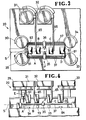
- the apparatus 20 processes a pair of stringers S (identical to the stringers 25, 26 shown in Figures 1 and 2) as they are fed along in a rightward direction ( Figures 3 and 4) along a feed path.
- the stringers S are gripped and transferred by a gripper mechanism F.
- the apparatus 20 also includes a pin attachement unit A, a first slider attachment unit B, a second slider attachment unit C, and a box pin attachment unit D all disposed on the feed path at longitudinal spaced intervals for attaching various components to the stringers S as they are transferred through the apparatus 20.
- the stringers S are finally cut off into a bidirectionally openable slide fastener by a cutter unit E.
- the pin attachment unit A is supplied with a pin from one of pin feeders 29, 30 dependent on whether a slide fastener to be manufactured should be provided with a right-hand pin or a left-hand pin. Then, the pin attachment unit A applies the supplied pin to an end of one of the stringers. Thereafter, a first slider (identical to the slider 23 shown in Figures 1 and 2) is supplied from a first slider feeder 31 to the first slider attachment unit B and attached thereby to the stringers, and a second slider (identical to the slider 2 4 shown in Figures 1 and 2) is supplied from a second slider feeder 32 to the second slider attachment unit and attached thereby to the stringers.
- the stringers with the first and second sliders 23, 24 are thus combined into a slide fastener chain.
- a box pin is supplied to the box pin attachment unit D from one of box pin feeders 33, 34 dependent on whether a slide fastener should have a right-hand or a left-hand pin, and attached by the box pin attachment unit D to an end of the other stringer. Finally, the fastener chain is cut off by the cutter unit E across an element-free gap in the chain into a completed bidirectionally openable slide fastener, which is discharged from the apparatus 20.
- the gripper mechanism F comprises a pair of laterally spaced grippers 35, 36 slidably movable on and along longitudinal guide rails 37 extending along the stringer feed path alongside of the pin attachment unit A, the first and second slider attachment units B, C, and the box pin attachment unit D. Since the grippers 35, 36 are symmetrically constructed, one of the grippers 35 will be described.
- the gripper 35 is composed of a slide base 38 slidable on and along the guide rails 37, a gripper base 39 mounted on the slide base 38 and laterally movable by a fluid cylinder 40 for adjusting the clearance gap between the stringers 25, 26, and a pair of upper and lower gripper jaws 41, 42 (Figure 6) pivotably mounted on an end of the gripper base 39 for gripping the stringer 25.
- the gripper jaws 41, 42 have rear end portions engaged by a wedge-shaped end of a rod 43a coupled to a piston 43 slidably disposed in a fluid cylinder 44 defined in the gripper base 39.
- the gripper jaws 41, 42 can be opened and closed to release and grip the stringer 25 by introducing a fluid into and discharging a fluid from the fluid cylinder 44.
- the fluid cylinder 40 for adjusting the clearance gap between the stringers 25, 26 is defined in the slide base 38 and has a piston 45 to which there is coupled a piston rod 46 connected to a joint plate 47 joined to a rear end of the gripper base 39. Therefore, the gripper base 39 can be laterally moved in a direction across the guide rails 37 by introducing a fluid into or discharging a fluid from the fluid cylinder 40.
- the gripper base 39 is normally urged to move inwardly toward the stringer 25 by a spring 48 acting between the joint plate 47 and the slide base 38.
- the slide base 38 is fastened by screws 49 to a belt 50 exten- ing along the guide rails 37 and coupled to a drive device (not shown). The slide base 38 can be slidably moved along the guide rails 37 by the belt 50.
- the pin attachment unit A is disposed on the feed path for the stringers as shown in Figure 3.
- the pin feeders 29, 30 for feeding left-hand and right-hand pins, respectively, have supply chutes 51, 52 coupled to the pin attachment unit A for supplying a selected pin to the pin attachment unit A, which attaches the supplied pin to one of the stringers.
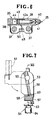
- the pin attachment unit A is composed of a pin holder 53 and a die assembly 54 disposed below the pin holder 53.
- the pin holder 53 is angularly movable about a shaft 55 between a first horizontal position, indicated by the two-dot-and-dash lines in Figure 7, to receive one of left-hand and right-hand pins from the supply chutes (only the supply chute 51 shown in Figure 7), and a second vertical position, indicated by the solid lines, to apply the supplied pin to one of the stringers.
- the pin holder 53 includes a holder body 56 and a pin support 57 movably supported on the holder body 56 and defining a pair of pin support slots 58, 59 opening upwardly toward the holder body 56 for accommodating left-hand and right-hand pins respectively therein.
- the pin holder 53 also has a pair of vertical punches 60, 61 disposed in alignment with the pin support slots 58, 59, respectively.
- the pin support 57 is normally urged by a spring 62 to move upwardly when the pin holder 53 is disposed vertically as shown in Figure 7.
- the die assembly 54 includes a die 63 supported on a die holder 64.
- Figure 5 shows the stringers 25, 26 gripped by the grippers 35, 36, the stringers 25, 26 being turned upside down while they are processed by the apparatus 20.
- the right-hand pin 27 is shown as being applied to the stringer 25. More specifically, the pin holder 53 receives the pin 27 from the chute 52 in the first horizontal position and then turned downwardly toward the second vertical position.
- the stringers 25, 26 are fed along by the gripper mechanism F until the ends of the stringers 25, 26 are inserted into between the holder body 56 and the pin support 57 in vertical alignment with the punches 60, 61. At this time, the end of the stringer 25 is inserted into a slot in the pin 27.
- the die 63 is moved upwardly by a suitable means (not shown) to press the pin support 57 upwardly, and simultaneously the punches 60, 61 are lowered by a suitable means (not shown) to attach the pin 27 to the end of the stringer 25 by staking. Thereafter, the die 63 is lowered and the pin support 57 is also depressed by a suitable means (not shown) to spread the pin support slots 58, 59, whereupon the stringers 25, 26, with the pin 27 attached to one of them, can pass through the pin holder 53. After one bidirectionally openable slide fastener has been completed, the pin support 57 is raised to restore the pin support slots 58, 59 in readiness for attachment of a next pin.
- the first and second slider attachment units B and C will now be described. Although the slider attachment units B and C are supplied with the oppositely directed sliders 23, 24, they are of the same construction. Therefore, the construction of the first slider attachment unit B only will be described.
- the first slider attachment unit B receives a slider 23 from a chute 65 connected to the first slider feeder 31, transfers the received. slider 23 into the stringer feed path, and threads the slider 23 over the stringers 25, 26.
- the first slider attachment unit B comprises a slider feeder 70 angularly movable about a shaft 71 between a first horizontal position for receiving the slider 23 from the chute 65 and a second vertical position for supporting-the slider 23, and a slider holder 72 for supporting the slider 23 between itself and the slider feeder 70.
- the slider feeder 70 has a clamp (not shown) for gripping the slider 23.
- the slider holder 72 is disposed below the slider feeder 70, and comprises a holder base 73 having a vertical slot 74, a stopper block 75 vertically movably disposed in the vertical slot 74 and actuatable by a fluid cylinder (not shown), and a locking block 76 vertically movable . disposed in the vertical slot 74 adjacent to the stopper block 75 and actuatable by a fluid cylinder (not shown).
- the stopper block 75 has a slider rest 77 and a stringer stop 78 on its upper end.
- the locking block 76 includes a pivotable locking lever 79 biased by a spring 80 for locking a pull tab 23a of the slider 23.
- the locking lever 79 engages and lowers the pull tab 23a under the resiliency of the spring 80 to support the slider 23 stably on the slider rest 77.
- the s,lider 23 is unlocked when the pull tab 23a is lowered by the locking lever 79, thus allowing the stringers to pass through the slider 23 smoothly.
- the stopper block 75 is lowered and the locking lever 79 is released from the pull tab 23a.
- the stringers 25, 26 are fed along through the slider 23 held by the clamp on the slider feeder 70 and the upper end of the locking block 76, during which time the stringers 25, 26 are progressively interengaged by the slider 23.
- the slider 24 is directed in an opposite direction, and the stringers 25, 26 as they pass through the slider 24 are progressively disengaged from each other.
- the locking block 76 is lowered and the slider feeder 70 is angularly moved upwardly to the first horizontal position to receive a next slider.
- the box pin attachment unit D is connected to chutes 81, 82 extending from the box pin feeders 33, 34, respectively.
- a box pin 28 is supplied to the box pin attachment unit D from the box pin feeder 33 when the pin 27 has been supplied from the pin feeder 30, and a box pin 28 is supplied to the box pin attachment unit D from the box pin feeder 34 when the pin 27 has been supplied from the pin feeder 29.
- the box pin attachment unit D comprises a box pin holder 83 and a die assembly 84 disposed below the pin holder 83.
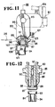
- the box pin holder 83 is angularly movable about a shaft 85 between a first horizontal position, indicated by the two-dot-and-dash lines in Figure 11, to receive a box pin from a selected one of the supply chutes (only the supply chute 81 shown in Figure 11), and a second vertical position, indicated by the solid lines, to apply the supplied box pin to the other stringer than the stringer to which the pin 27 has already been attached.
- the chutes 81, 82 are positioned downstream of the box pin holder 83 in the direction of the stringer feed path as shown in Figures 1 and 11 and upwardly of the die assembly 84, so that the box pin holder 83 can swing back upwardly out of the feed path into the first horizontal position, thereby allowing the attached box pin 28 pass through the box pin attachment unit D.
- the box pin holder 83 includes a holder body 86 and a box pin support 87 movably supported on the holder body 86 and defining a pair of box pin support slots 88, 89 opening upwardly toward the holder body 86 for accommodating box pins respectively therein.
- the box pin holder 83 also has a pair of vertical punches 90, 91 disposed in alignment with the pin support slots 88, 89, respectively.
- the box pin support 87 is normally urged by a spring 92 to move upwardly when the box pin holder 83 is disposed vertically as shown in Figure 11.
- the die assembly 84 includes a die 93 supported on a die holder 94.
- the box pin support 87 has an upwardly opening hole 95 housing therein a tapered gate 96 urged to move upwardly into the box pin support slot 89 under the resiliency of a spring 97.
- a similar gate mounted in the box pin support 87 and spring-biased into the box pin support slot 88.
- a shutter 98 is slidably mounted in the box pin holder 83 and the box pin support 87 across the box pin support slot 88.
- a similar shutter extends across the other box pin support slot 88.
- the gate 96 and the shutter 98 cooperate with each other in retaining a box pin 28 within the box pin support slot 89.
- the gate 96 serves to prevent the supplied box pin 28 from dropping out of the box pin support slot 89 and to guide the leading end of the stringer with a tapered upper end thereof.
- the shutter 98 has a hole 99 defined therethrough, the hole 99 being brought into registration with the box in support slot 89 when a box pin 28 is to be supplied into the box pin support slot 89.
- the shutter 90 is normally urged by a spring 100 in a direction to displace the hole 99 out of registration with the box pin support slot 89.
- the holder body 86 supports a presser pin 101 having a rounded end 102 engaging with a slanted surface 103 of the shutter 98.
- the presser pin 101 is engaged by a fixed base 104 and is moved to cause the rounded end 102 to displace the shutter 98 until the hole 99 is aligned with the box pin support slot 89.
- An angular stopper 105 is pivotably supported by a pin 106 on the holder body 86 for keeping the box pin support 87 spaced from the holder body 86 to spread the box pin support slot 89. More specifically, the stopper 105 can be angularly moved about the pin 106 into engagement with the box pin supoprt 87 to hold the same spaced from the holder body 86 as shown in Figure 15-.
- the die assembly 84 also includes a locking lever 106 pivotably mounted on the die 93 and having a hooked end 107 lockingly engageable with the box pin support 87.
- Figures 13 through 16 illustrate the progressive steps of applying a box pin 28 to a slide fastener stringer.
- the box pin holder 83 is in the horizontal position in which the stopper 105 is engaged by the fixed base 104 to disengage from the box pin support 87, thus restoring the box pin support slot 89.
- the presser pin 102 is also engaged by the fixed base 104 to displace the shutter 98 until the hole 99 is held in registration with the box pin support slot 89.
- the box pin 28 is supplied from the chute 81 ( Figure 11) into the box pin support slot 89.
- the box pin holder 83 is then angularly moved to the vertical position of Figure 14 in which the shutter 98 is displaced upwardly under the force of the spring 100.
- the box pin 28 is retained in the box pin support slot 89 by the shutter 98 and the gate 96, with the stringer 26 being about to enter a slot in the box pin 28.
- the stringers 25, 26 are spread apart by the grippers 35, 36, such that the stringer 26 is inserted into the slot in the box pin 28 supported in the box pin support slot 89, with the stringer 25 to which the pin 27 has been attached being laterally spaced from the box pin support 87.
- the die 93 is raised to press the box pin support 87 and the punch 91 is lowered to apply the box pin 28 to the stringer 26.
- the die 93 is lowered to cause the locking lever 106 to pull the box pin support 87 downwardly to spread the box pin support slot 89.
- the gate 96 is also lowered, and the stopper 105 engages the box pin support 87 to keep the box pin support slot 89 spread widely.
- the box pin holder 83 is angularly moved to the horizontal position as shown in Figure 16, whereupon the stringer 26 with the box pin 28 applied is extracted from the box pin support slot 89.
- the stringers 25, 26 are then fed again by the grippers 35, 36.
- the stopper 105 is engaged by the fixed base 104 to allow the box pin support 87 to be displaced toward the holder body 86, and the presser pin 101 is about to displace the shutter 98 to bring the hole 99 into registration with the box pin support slot 89.
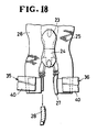
- Figure 18 shows the condition in which the stringers 25, 26 with the sliders 23, 24 mounted thereon and the pin 27 attached to the stringer 25 are spread apart by the grippers 35, 36, and the box pin 28 is about to be attached to the stringer 26.
- Bidireotionally openable slide fasteners with right-hand and left-hand pins can be manufactured as desired on the apparatus 20 of the invention by selecting one of the pin supply feeders 29, 30 to feed a pin 27 to the pin attachment unit A for attachment to one of the stringers 25, 26 and also selecting one of the box pin supply feeders 33, 34 to feed a box pin 28 to the box pin attachment unit D for attachment to the other stringer.
- the pin supply feeders 29, 30 and the box pin supply feeders 33, 34 can be selected by electrically or mechanically transmitting a command to them in timed relation to operation of the attachment units A, D.
Landscapes
- Slide Fasteners (AREA)
Applications Claiming Priority (4)
| Application Number | Priority Date | Filing Date | Title |
|---|---|---|---|
| JP94128/84 | 1984-05-11 | ||
| JP59094128A JPS60236604A (ja) | 1984-05-11 | 1984-05-11 | 逆開きスライドフアスナ−の製造装置 |
| JP59094129A JPS60236603A (ja) | 1984-05-11 | 1984-05-11 | 逆開きスライドフアスナ−の箱棒取付装置 |
| JP94129/84 | 1984-05-11 |
Publications (3)
| Publication Number | Publication Date |
|---|---|
| EP0160982A2 true EP0160982A2 (fr) | 1985-11-13 |
| EP0160982A3 EP0160982A3 (en) | 1988-09-21 |
| EP0160982B1 EP0160982B1 (fr) | 1990-08-22 |
Family
ID=26435434
Family Applications (1)
| Application Number | Title | Priority Date | Filing Date |
|---|---|---|---|
| EP85105637A Expired - Lifetime EP0160982B1 (fr) | 1984-05-11 | 1985-05-08 | Appareil pour la fabrication de fermetures à glissière du type comportant deux curseurs |
Country Status (12)
| Country | Link |
|---|---|
| US (1) | US4625398A (fr) |
| EP (1) | EP0160982B1 (fr) |
| KR (1) | KR860001939B1 (fr) |
| AU (1) | AU557351B2 (fr) |
| BR (1) | BR8502316A (fr) |
| CA (1) | CA1260245A (fr) |
| DE (1) | DE3579252D1 (fr) |
| ES (1) | ES8606997A1 (fr) |
| GB (1) | GB2158505B (fr) |
| HK (1) | HK40089A (fr) |
| MY (1) | MY100668A (fr) |
| SG (1) | SG25389G (fr) |
Cited By (2)
| Publication number | Priority date | Publication date | Assignee | Title |
|---|---|---|---|---|
| EP0269912A1 (fr) * | 1986-11-14 | 1988-06-08 | Yoshida Kogyo K.K. | Appareil de fabrication de fermetures à glissiére du type comportant deux curseurs |
| EP0302362A1 (fr) * | 1987-08-04 | 1989-02-08 | Yoshida Kogyo K.K. | Dispositif pour mettre en place des éléments constitutifs d'une fermeture à glissière |
Families Citing this family (8)
| Publication number | Priority date | Publication date | Assignee | Title |
|---|---|---|---|---|
| JPH0527046Y2 (fr) * | 1986-04-15 | 1993-07-09 | ||
| JPH074294B2 (ja) * | 1986-06-25 | 1995-01-25 | ワイケイケイ株式会社 | スライダ−保持装置 |
| JPH0636737Y2 (ja) * | 1986-07-15 | 1994-09-28 | 吉田工業株式会社 | スライドフアスナ−チエ−ンのスライダ−嵌插装置 |
| MY101685A (en) * | 1986-10-28 | 1991-12-31 | Yoshida Kogyo Kk | Apparatus for manufacturing slide fasteners |
| US4882824A (en) * | 1988-07-05 | 1989-11-28 | Scovill Fasteners Inc. | Apparatus for installing sliders on a gapped slide fastener chain |
| US5142772A (en) * | 1991-09-06 | 1992-09-01 | Yoshida Kogyo K.K. | Apparatus for manufacturing slide fasteners each having a selected number of sliders |
| JP2004215771A (ja) * | 2003-01-10 | 2004-08-05 | Ykk Corp | スライドファスナーの仕上装置 |
| TWI631916B (zh) * | 2017-05-24 | 2018-08-11 | 中傳企業股份有限公司 | 拉鍊頭組合結構及其梢狀組件 |
Family Cites Families (8)
| Publication number | Priority date | Publication date | Assignee | Title |
|---|---|---|---|---|
| US3081462A (en) * | 1960-06-30 | 1963-03-19 | New York Notion Co Inc | Slide fastener tapes and the method of making same |
| US3714698A (en) * | 1970-03-14 | 1973-02-06 | Yoshida Kogyo Kk | Method and machine for assembling slide fasteners of separable type |
| FR2129954B1 (fr) * | 1971-03-23 | 1974-08-23 | Yoshida Kogyo Kk | |
| JPS5933371B2 (ja) * | 1979-12-15 | 1984-08-15 | ワイケイケイ株式会社 | スライドフアスナ−の製造方法 |
| JPS5911805A (ja) * | 1982-07-10 | 1984-01-21 | ワイケイケイ株式会社 | 開離嵌挿具付スライドファスナの製造装置 |
| JPS5911806A (ja) * | 1982-07-10 | 1984-01-21 | ワイケイケイ株式会社 | 開離嵌挿具付スライドファスナに棒金具を取付ける装置 |
| AU543216B2 (en) * | 1982-11-16 | 1985-04-04 | Yoshida Kogyo K.K. | Finishing slide fasteners |
| JPS6024802A (ja) * | 1983-07-20 | 1985-02-07 | ワイケイケイ株式会社 | 逆開き金具付きスライドフアスナの製造方法 |
-
1985
- 1985-03-11 AU AU39714/85A patent/AU557351B2/en not_active Ceased
- 1985-03-12 GB GB08506399A patent/GB2158505B/en not_active Expired
- 1985-03-14 CA CA000476501A patent/CA1260245A/fr not_active Expired
- 1985-05-03 US US06/730,177 patent/US4625398A/en not_active Expired - Fee Related
- 1985-05-08 KR KR1019850003121A patent/KR860001939B1/ko not_active Expired
- 1985-05-08 EP EP85105637A patent/EP0160982B1/fr not_active Expired - Lifetime
- 1985-05-08 DE DE8585105637T patent/DE3579252D1/de not_active Expired - Lifetime
- 1985-05-09 ES ES542963A patent/ES8606997A1/es not_active Expired
- 1985-05-10 BR BR8502316A patent/BR8502316A/pt not_active IP Right Cessation
-
1987
- 1987-07-23 MY MYPI87001087A patent/MY100668A/en unknown
-
1989
- 1989-04-13 SG SG253/89A patent/SG25389G/en unknown
- 1989-05-11 HK HK400/89A patent/HK40089A/xx not_active IP Right Cessation
Cited By (3)
| Publication number | Priority date | Publication date | Assignee | Title |
|---|---|---|---|---|
| EP0269912A1 (fr) * | 1986-11-14 | 1988-06-08 | Yoshida Kogyo K.K. | Appareil de fabrication de fermetures à glissiére du type comportant deux curseurs |
| EP0302362A1 (fr) * | 1987-08-04 | 1989-02-08 | Yoshida Kogyo K.K. | Dispositif pour mettre en place des éléments constitutifs d'une fermeture à glissière |
| US4835845A (en) * | 1987-08-04 | 1989-06-06 | Yoshida Kogyo K. K. | Parts applicator for slide fasteners |
Also Published As
| Publication number | Publication date |
|---|---|
| SG25389G (en) | 1989-07-14 |
| CA1260245A (fr) | 1989-09-26 |
| MY100668A (en) | 1991-01-17 |
| GB2158505B (en) | 1987-09-03 |
| KR860001939B1 (ko) | 1986-11-01 |
| DE3579252D1 (de) | 1990-09-27 |
| US4625398A (en) | 1986-12-02 |
| ES542963A0 (es) | 1986-06-01 |
| AU557351B2 (en) | 1986-12-18 |
| BR8502316A (pt) | 1986-01-21 |
| EP0160982A3 (en) | 1988-09-21 |
| EP0160982B1 (fr) | 1990-08-22 |
| GB2158505A (en) | 1985-11-13 |
| AU3971485A (en) | 1985-11-14 |
| KR850007919A (ko) | 1985-12-11 |
| GB8506399D0 (en) | 1985-04-11 |
| HK40089A (en) | 1989-05-19 |
| ES8606997A1 (es) | 1986-06-01 |
Similar Documents
| Publication | Publication Date | Title |
|---|---|---|
| EP0160982B1 (fr) | Appareil pour la fabrication de fermetures à glissière du type comportant deux curseurs | |
| EP0030707B1 (fr) | Appareil pour la mise en place des curseurs et des butées d'arrêt pour fermetures à glissière | |
| EP0099064B1 (fr) | Procédé et appareil pour fixer une butée d'arrêt inférieure séparable à une paire de rubans d'une fermeture à glissière | |
| EP0147771B1 (fr) | Appareil pour mettre en place des curseurs de fermetures à glissière de type masquées | |
| GB2164699A (en) | A space portion processing method and apparatus for a slide fastener chain | |
| CA1238476A (fr) | Methode et dispositif de faconnage d'entre-deux dans une paire d'enchainements de fermetures a glissiere escamotees | |
| EP0099065B1 (fr) | Dispositif de fabrication de fermetures à glissière séparables | |
| US4839956A (en) | Method of and apparatus for attaching top stops to slide fastener chain | |
| EP0097343B1 (fr) | Appareil pour la pose automatique de curseurs sur des bandes de fermeture à glissière | |
| EP0376229A1 (fr) | Méthode pour fixer des éléments d'accouplement sur un ruban de fermeture à glissière | |
| JP2926294B2 (ja) | スライダーの引手取付装置 | |
| US4325185A (en) | Apparatus for gapping a continuous slide fastener stringer | |
| US4787140A (en) | Apparatus for attaching top end stops to a continuous slide fastener chain | |
| US4697319A (en) | Apparatus for attaching boxes to slide fasteners with separable box and pin of synthetic resin | |
| EP0097342B1 (fr) | Appareil pour la pose automatique de curseurs sur des bandes de fermeture à glissière | |
| JPH0128565B2 (fr) | ||
| EP0303215B1 (fr) | Appareil pour fixer des butées d'extrémité supérieure sur une chaîne de fermetures à glissière | |
| JPH06258B2 (ja) | タブ収納装置 | |
| GB2200687A (en) | Apparatus for threading a slider onto opposed stringers for slide fastener |
Legal Events
| Date | Code | Title | Description |
|---|---|---|---|
| PUAI | Public reference made under article 153(3) epc to a published international application that has entered the european phase |
Free format text: ORIGINAL CODE: 0009012 |
|
| AK | Designated contracting states |
Designated state(s): BE DE FR IT NL |
|
| PUAL | Search report despatched |
Free format text: ORIGINAL CODE: 0009013 |
|
| AK | Designated contracting states |
Kind code of ref document: A3 Designated state(s): BE DE FR IT NL |
|
| 17P | Request for examination filed |
Effective date: 19881202 |
|
| 17Q | First examination report despatched |
Effective date: 19891004 |
|
| GRAA | (expected) grant |
Free format text: ORIGINAL CODE: 0009210 |
|
| AK | Designated contracting states |
Kind code of ref document: B1 Designated state(s): BE DE FR IT NL |
|
| ITF | It: translation for a ep patent filed | ||
| ET | Fr: translation filed | ||
| REF | Corresponds to: |
Ref document number: 3579252 Country of ref document: DE Date of ref document: 19900927 |
|
| PLBE | No opposition filed within time limit |
Free format text: ORIGINAL CODE: 0009261 |
|
| STAA | Information on the status of an ep patent application or granted ep patent |
Free format text: STATUS: NO OPPOSITION FILED WITHIN TIME LIMIT |
|
| 26N | No opposition filed | ||
| ITTA | It: last paid annual fee | ||
| PGFP | Annual fee paid to national office [announced via postgrant information from national office to epo] |
Ref country code: BE Payment date: 19940222 Year of fee payment: 10 |
|
| PGFP | Annual fee paid to national office [announced via postgrant information from national office to epo] |
Ref country code: NL Payment date: 19940531 Year of fee payment: 10 |
|
| ITPR | It: changes in ownership of a european patent |
Owner name: CAMBIO RAGIONE SOCIALE;YKK CORPORATION |
|
| REG | Reference to a national code |
Ref country code: FR Ref legal event code: CD |
|
| PG25 | Lapsed in a contracting state [announced via postgrant information from national office to epo] |
Ref country code: BE Effective date: 19950531 |
|
| BERE | Be: lapsed |
Owner name: YOSHIDA KOGYO K.K. Effective date: 19950531 |
|
| PG25 | Lapsed in a contracting state [announced via postgrant information from national office to epo] |
Ref country code: NL Effective date: 19951201 |
|
| NLV4 | Nl: lapsed or anulled due to non-payment of the annual fee |
Effective date: 19951201 |
|
| PGFP | Annual fee paid to national office [announced via postgrant information from national office to epo] |
Ref country code: FR Payment date: 20030508 Year of fee payment: 19 |
|
| PGFP | Annual fee paid to national office [announced via postgrant information from national office to epo] |
Ref country code: DE Payment date: 20030515 Year of fee payment: 19 |
|
| PG25 | Lapsed in a contracting state [announced via postgrant information from national office to epo] |
Ref country code: DE Free format text: LAPSE BECAUSE OF NON-PAYMENT OF DUE FEES Effective date: 20041201 |
|
| PG25 | Lapsed in a contracting state [announced via postgrant information from national office to epo] |
Ref country code: FR Free format text: LAPSE BECAUSE OF NON-PAYMENT OF DUE FEES Effective date: 20050131 |
|
| REG | Reference to a national code |
Ref country code: FR Ref legal event code: ST |