EP0161430A2 - Amortisseur de choc - Google Patents
Amortisseur de choc Download PDFInfo
- Publication number
- EP0161430A2 EP0161430A2 EP85103408A EP85103408A EP0161430A2 EP 0161430 A2 EP0161430 A2 EP 0161430A2 EP 85103408 A EP85103408 A EP 85103408A EP 85103408 A EP85103408 A EP 85103408A EP 0161430 A2 EP0161430 A2 EP 0161430A2
- Authority
- EP
- European Patent Office
- Prior art keywords
- vortex
- chamber
- vortex chamber
- piston
- passages
- Prior art date
- Legal status (The legal status is an assumption and is not a legal conclusion. Google has not performed a legal analysis and makes no representation as to the accuracy of the status listed.)
- Granted
Links
- 230000035939 shock Effects 0.000 title claims abstract description 23
- 239000006096 absorbing agent Substances 0.000 title claims abstract description 15
- 239000012530 fluid Substances 0.000 claims abstract description 33
- 239000000725 suspension Substances 0.000 description 5
- 238000013016 damping Methods 0.000 description 4
- 230000006835 compression Effects 0.000 description 3
- 238000007906 compression Methods 0.000 description 3
- 230000001133 acceleration Effects 0.000 description 1
- 238000006073 displacement reaction Methods 0.000 description 1
- 230000000694 effects Effects 0.000 description 1
- 238000004519 manufacturing process Methods 0.000 description 1
- 238000007789 sealing Methods 0.000 description 1
Images

Classifications
-
- F—MECHANICAL ENGINEERING; LIGHTING; HEATING; WEAPONS; BLASTING
- F16—ENGINEERING ELEMENTS AND UNITS; GENERAL MEASURES FOR PRODUCING AND MAINTAINING EFFECTIVE FUNCTIONING OF MACHINES OR INSTALLATIONS; THERMAL INSULATION IN GENERAL
- F16F—SPRINGS; SHOCK-ABSORBERS; MEANS FOR DAMPING VIBRATION
- F16F9/00—Springs, vibration-dampers, shock-absorbers, or similarly-constructed movement-dampers using a fluid or the equivalent as damping medium
- F16F9/32—Details
- F16F9/34—Special valve constructions; Shape or construction of throttling passages
- F16F9/344—Vortex flow passages
-
- B—PERFORMING OPERATIONS; TRANSPORTING
- B60—VEHICLES IN GENERAL
- B60G—VEHICLE SUSPENSION ARRANGEMENTS
- B60G13/00—Resilient suspensions characterised by arrangement, location or type of vibration dampers
- B60G13/02—Resilient suspensions characterised by arrangement, location or type of vibration dampers having dampers dissipating energy, e.g. frictionally
- B60G13/06—Resilient suspensions characterised by arrangement, location or type of vibration dampers having dampers dissipating energy, e.g. frictionally of fluid type
- B60G13/08—Resilient suspensions characterised by arrangement, location or type of vibration dampers having dampers dissipating energy, e.g. frictionally of fluid type hydraulic
Definitions
- the present invention relates to a hydraulic shock absorber including a piston disposed within a hollow cylinder in movable position responsive to a shock applied thereto, said piston defining a hollow vortex chamber therein, said vortex chamber being communicated with fluid chambers defined in the hollow cylinder to introduce a working fluid and to generate a vortex pattern fluid flow therein for producing an absorbing force.
- Pistons having two vortex chambers to produce a damping force both in piston compression stroke and piston expansion stroke are known per se from the DE-C-697 779, the US-A-3 220 517 and the GB-A-600 386.
- the shock absorber according to the invention is characterized in that said piston comprises upper and lower members assembled together for defining therein a vortex chamber, said upper and lower members being formed with vertically extending recesses on the periphery thereof, the recesses formed in the upper and lower members being aligned with respect to one another and defining vertical vortex passages, said piston further defining vortex passages having inner ends tangentially opening into said vortex chamber and outer ends opening into said vertical vortex passages, said vortex chamber being divided into upper and lower sections disposed within said vortex chamber, said upper and lower sections communicating with each other via said vertically extending recesses and vortex passages and in that said upper chamber of said fluid chamber communicates with said upper section of said vortex chamber via a communication means and that said lower chamber communicates with said lower section of said vortex chamber via a communication means.
- the shock absorber comprises a cylindrical tube 2 and a piston 3 movably disposed within the cylinder tube 2 along the longitudinal axis of the cylinder tube.
- the piston is secured on the lower end of a piston rod 4 which has an upper end extending from the tube 2 and attached to a vehicle body chassis (not shown).
- the lower end of the tube 2 is attached to a wheel axle (not shown).
- a free piston 5 with an annular sealing ring 8 is also disposed within the tube 2 to define therein a pneumatic chamber 6.
- a chamber 7 difined above the free piston 5 is filled with a working fluid.
- the chamber 7 is divided into the upper and lower chamber 7a and 7b by the piston 3.
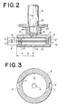
- the piston 3 is formed with a pair of vortex chambers 9 and 10 respectively of circular in transverse section. Also, the piston 3 is formed with a recesses 13 on the outer circumference.
- the upper vortex chamber 9 communicates with the recess 13 via fluid passages 11, each of which has an outer end opening into the recesses 13 and an inner end opening into the upper vortex chamber 9 in the direction substantially along the normal of the circle of the upper vortex chamber 9.
- the lower vortex chamber 10 communicates with the recesses 13 via fluid passages 12.
- Each of the fluid passage has an outer end opening into the recesses 13 and an inner end opening to the lower vortex in the direction perpendicular to the longitudinal axis of the lower vortex chamber.
- the upper and lower vortex chambers 9 and 10 communicate with one another via the fluid passage 11, the recess 13 and the fluid passage 12.
- the upper vortex chamber 9 also communicates with the upper chamber 7a via fluid passages 14 radially extending from a threaded opening 20 for engagement with the threaded end 22 of the piston rod, and an opening 24 for communication between the threaded opening 20 and the upper vortex chamber 9.
- the lower vortex chamber 10 communicates with the lower chamber 7b .via an opening 15 formed in the bottom of the lower vortex chamber.
- a suspension spring of a vehicle suspension mechanism In operation, if the vehicle is subject to road shock, a suspension spring of a vehicle suspension mechanism is displaced to absorb the shock. The vehicle will move up and down due to displacement of the suspension spring until the spring returns to the normal state. At this time, the shock absorber works to reduce the vehicle vibration by absorbing the shock.
- the piston 3 In the compression stroke of the piston 3, the piston 3 travels downwardly to expand the volume of the upper chamber 7a and, in turn, reduce the volume of the lower chamber 7b.
- the fluid pressure in the upper chamber 7a is reduced and the fluid pressure in the lower chamber 7b is increased to create a pressure difference between the upper and lower chambers 7a and 7b.
- the fluid in the lower chamber 7b flows into the upper chamber 7a via the piston 3.
- the fluid in the chamber 7b enters the lower vortex chamber 10 through the opening 15.
- the fluid flows via the lower vortex chamber 10, the fluid passages 12, the recess 13 and the fluid passage 11 into the upper vortex chamber 9.
- the fluid is discharged into the upper chamber 7a in the direction - substantially along the normal of the circle of the upper vortex chamber in order to produce a vortex therein. Thereafter, the fluid flows into the upper chamber 7a via .the opening 24 and the passages 14.
- the fluid passages 11 and 12 serve as orifices to limit the flow amount of the fluid. In the compression stroke, therefore, the shock absorber 1 absorbs the shock applied to the vehicle by the vortex-and-orifice effect, both serving to limit the fluid flow.
- the volume of the upper chamber 7a is reduced and the volume of the lower chamber 7b is increased to induce fluid flow via the piston 3.
- the vortex is produced in the lower vortex chamber 10 in order to generate the shock absorbing force.
Landscapes
- Engineering & Computer Science (AREA)
- General Engineering & Computer Science (AREA)
- Mechanical Engineering (AREA)
- Fluid-Damping Devices (AREA)
- Vehicle Body Suspensions (AREA)
Applications Claiming Priority (2)
| Application Number | Priority Date | Filing Date | Title |
|---|---|---|---|
| JP10896580A JPS5733240A (en) | 1980-08-07 | 1980-08-07 | Shock absorber |
| JP108965/80 | 1980-08-07 |
Related Parent Applications (3)
| Application Number | Title | Priority Date | Filing Date |
|---|---|---|---|
| EP81106177A Division-Into EP0045954B1 (fr) | 1980-08-07 | 1981-08-06 | Amortisseur de choc |
| EP81106177A Division EP0045954B1 (fr) | 1980-08-07 | 1981-08-06 | Amortisseur de choc |
| EP81106177.9 Division | 1981-08-06 |
Publications (3)
| Publication Number | Publication Date |
|---|---|
| EP0161430A2 true EP0161430A2 (fr) | 1985-11-21 |
| EP0161430A3 EP0161430A3 (en) | 1986-06-25 |
| EP0161430B1 EP0161430B1 (fr) | 1988-11-09 |
Family
ID=14498144
Family Applications (2)
| Application Number | Title | Priority Date | Filing Date |
|---|---|---|---|
| EP81106177A Expired EP0045954B1 (fr) | 1980-08-07 | 1981-08-06 | Amortisseur de choc |
| EP85103408A Expired EP0161430B1 (fr) | 1980-08-07 | 1981-08-06 | Amortisseur de choc |
Family Applications Before (1)
| Application Number | Title | Priority Date | Filing Date |
|---|---|---|---|
| EP81106177A Expired EP0045954B1 (fr) | 1980-08-07 | 1981-08-06 | Amortisseur de choc |
Country Status (4)
| Country | Link |
|---|---|
| US (1) | US4418802A (fr) |
| EP (2) | EP0045954B1 (fr) |
| JP (1) | JPS5733240A (fr) |
| DE (1) | DE3176930D1 (fr) |
Families Citing this family (21)
| Publication number | Priority date | Publication date | Assignee | Title |
|---|---|---|---|---|
| US4502575A (en) * | 1980-08-13 | 1985-03-05 | Nissan Motor Company, Limited | Shock absorber |
| FR2513340A1 (fr) * | 1981-09-23 | 1983-03-25 | Peugeot | Piston a clapets pour amortisseur |
| JPS58211037A (ja) * | 1982-05-31 | 1983-12-08 | Nissan Motor Co Ltd | シヨツクアブソ−バ |
| JPH0645400B2 (ja) * | 1984-03-09 | 1994-06-15 | 株式会社タツノ・メカトロニクス | 給油装置 |
| JPH085519B2 (ja) * | 1987-07-21 | 1996-01-24 | 株式会社タツノ・メカトロニクス | 洩油検知装置 |
| US5070972A (en) * | 1990-06-18 | 1991-12-10 | General Motors Corporation | Vortex valving assembly for a hydraulic damper |
| IT1266168B1 (it) * | 1994-07-15 | 1996-12-23 | Manuli Rubber Ind Srl | Tubo flessibile a doppia carcassa |
| RU2180060C2 (ru) * | 2000-01-12 | 2002-02-27 | Рябинин Михаил Вячеславович | Гидравлический демпфер |
| RU2269042C2 (ru) * | 2001-11-08 | 2006-01-27 | Закрытое акционерное общество "Плаза" | Амортизатор с газовой полостью в штоке |
| RU2269703C2 (ru) * | 2002-07-17 | 2006-02-10 | ЗАО "Плаза" | Крыльчатый амортизатор |
| RU2253574C2 (ru) * | 2002-08-13 | 2005-06-10 | Закрытое Акционерное Общество "Плаза" (ЗАО "Плаза") | Однотрубный амортизатор |
| RU2253575C2 (ru) * | 2002-08-13 | 2005-06-10 | Закрытое акционерное общество "Плаза" (ЗАО "Плаза ") | Однотрубный амортизатор |
| RU2256111C2 (ru) * | 2002-10-14 | 2005-07-10 | ЗАО "Плаза" | Однотрубный амортизатор с полостью в штоке |
| RU2263835C2 (ru) * | 2003-07-07 | 2005-11-10 | ЗАО "Плаза" | Арктический амортизатор подвески транспортного средства |
| RU2256832C2 (ru) * | 2003-08-25 | 2005-07-20 | ЗАО "Плаза" | Арктический амортизатор |
| RU2279582C1 (ru) * | 2005-01-11 | 2006-07-10 | Владимир Викторович Ковалев | Амортизатор с гидравлическим буфером отбоя |
| RU2291790C1 (ru) * | 2005-08-15 | 2007-01-20 | Открытое акционерное общество "КАМАЗ" | Система подрессоривания транспортного средства |
| DE102005061164B4 (de) * | 2005-12-21 | 2007-09-13 | Zf Friedrichshafen Ag | Schwingungsdämpfer mit einer Anschlagfeder |
| JP6245646B2 (ja) * | 2014-04-08 | 2017-12-13 | 株式会社ブリヂストン | 防振装置 |
| RU168465U1 (ru) * | 2016-09-14 | 2017-02-06 | Общество с ограниченной ответственностью "Первоуральский Автоагрегатный завод" | Гидравлический амортизатор |
| RU204114U1 (ru) * | 2020-12-28 | 2021-05-07 | Федеральное государственное бюджетное образовательное учреждение высшего образования "Санкт-Петербургский государственный архитектурно-строительный университет" | Пневмогидравлический амортизатор |
Family Cites Families (12)
| Publication number | Priority date | Publication date | Assignee | Title |
|---|---|---|---|---|
| DE697799C (de) * | 1937-05-27 | 1940-10-23 | Ver Deutsche Metallwerke Ag | Fluessigkeitsstossdaempfer |
| FR845638A (fr) | 1937-11-10 | 1939-08-29 | Kronprinz Ag Fu R Metallindust | Dispositif de suspension applicable par exemple aux trains d'atterrissage pour avions |
| DE739989C (de) | 1941-01-23 | 1943-10-09 | Fritz Faudi | Einrichtung zur Verhinderung von OElschlaegen bei Luftfedern mit in einem Zylinder verschiebbarem Kolben |
| BE479002A (fr) | 1944-10-13 | |||
| US3133615A (en) * | 1962-07-02 | 1964-05-19 | Bendix Corp | Hydraulic shock absorber with improved piston valve means |
| BE639280A (fr) | 1962-10-30 | 1900-01-01 | ||
| DE1505478A1 (de) * | 1965-10-29 | 1969-09-25 | Bilstein August Fa | Stufenlos verstellbarer Stossdaempfer,insbesondere fuer Kraftfahrzeuge |
| US3672474A (en) * | 1970-02-16 | 1972-06-27 | Bendix Corp | Fluid flow device for a shock absorber |
| US4082169A (en) * | 1975-12-12 | 1978-04-04 | Bowles Romald E | Acceleration controlled fluidic shock absorber |
| DE2905928A1 (de) * | 1979-02-16 | 1980-08-28 | Fichtel & Sachs Ag | Hydropneumatischer zweirohrschwingungsdaempfer mit entlueftungsventil |
| GB2044882B (en) | 1979-02-27 | 1983-10-26 | Nissan Motor | Hydraulic shock absorber with vortex valve |
| DE2950888A1 (de) | 1979-12-18 | 1981-06-25 | Stabilus Gmbh | Daempfkolben fuer pneumatische, hydraulische und hydropneumatische aggregate |
-
1980
- 1980-08-07 JP JP10896580A patent/JPS5733240A/ja active Pending
-
1981
- 1981-07-20 US US06/285,049 patent/US4418802A/en not_active Expired - Fee Related
- 1981-08-06 EP EP81106177A patent/EP0045954B1/fr not_active Expired
- 1981-08-06 EP EP85103408A patent/EP0161430B1/fr not_active Expired
- 1981-08-06 DE DE8181106177T patent/DE3176930D1/de not_active Expired
Also Published As
| Publication number | Publication date |
|---|---|
| EP0045954A2 (fr) | 1982-02-17 |
| DE3176930D1 (en) | 1988-12-15 |
| EP0161430A3 (en) | 1986-06-25 |
| EP0045954B1 (fr) | 1988-11-09 |
| JPS5733240A (en) | 1982-02-23 |
| US4418802A (en) | 1983-12-06 |
| EP0161430B1 (fr) | 1988-11-09 |
| EP0045954A3 (en) | 1983-02-23 |
Similar Documents
| Publication | Publication Date | Title |
|---|---|---|
| EP0161430A2 (fr) | Amortisseur de choc | |
| EP0336692B1 (fr) | Amortisseur de chocs | |
| US5598903A (en) | Acceleration sensitive flow sensitive mcpherson strut | |
| US4145067A (en) | Suspension system for a motor vehicle | |
| US3752498A (en) | Oleo-pneumatic suspension assembly | |
| US3677561A (en) | Adjustable shock absorber assemblies | |
| US4262779A (en) | Shock absorber with reservoir and working chamber communicating structure | |
| EP0122532B1 (fr) | Amortisseur de chocs | |
| EP1110768B1 (fr) | Dispositif de suspension de véhicule | |
| US4515252A (en) | Piston stroke responsive vortex-flow shock absorber | |
| US20030001359A1 (en) | Front fork | |
| WO1998014718A1 (fr) | Amortisseur mcpherson sensible a l'acceleration et au flux | |
| US4475635A (en) | Vortex flow shock absorber with one-way valve | |
| JPH0719643U (ja) | 車両用緩衝装置 | |
| US4635766A (en) | Automotive suspension strut with increased stroke | |
| CN110594341A (zh) | 一种汽车悬架用筒式减震器 | |
| EP0053378A2 (fr) | Soupape à écoulement tourbillant et à dispositif de décompression pour amortisseur de choc | |
| JPS5865340A (ja) | 油圧緩衝器 | |
| GB1588267A (en) | Motorcycle suspension | |
| SU1135934A1 (ru) | Гидравлический амортизатор | |
| GB2081419A (en) | Hydraulic shock absorber | |
| JPS59131049A (ja) | シヨツクアブソ−バ | |
| JPS6120340Y2 (fr) | ||
| JP2996984B2 (ja) | 倒立型フロントフォークのオイルロック機構 | |
| JP3100398U (ja) | 油圧緩衝器 |
Legal Events
| Date | Code | Title | Description |
|---|---|---|---|
| PUAI | Public reference made under article 153(3) epc to a published international application that has entered the european phase |
Free format text: ORIGINAL CODE: 0009012 |
|
| 17P | Request for examination filed |
Effective date: 19850322 |
|
| AC | Divisional application: reference to earlier application |
Ref document number: 45954 Country of ref document: EP |
|
| AK | Designated contracting states |
Designated state(s): DE FR GB |
|
| PUAL | Search report despatched |
Free format text: ORIGINAL CODE: 0009013 |
|
| AK | Designated contracting states |
Kind code of ref document: A3 Designated state(s): DE FR GB |
|
| 17Q | First examination report despatched |
Effective date: 19870513 |
|
| GRAA | (expected) grant |
Free format text: ORIGINAL CODE: 0009210 |
|
| AC | Divisional application: reference to earlier application |
Ref document number: 45954 Country of ref document: EP |
|
| AK | Designated contracting states |
Kind code of ref document: B1 Designated state(s): DE FR GB |
|
| REF | Corresponds to: |
Ref document number: 3176931 Country of ref document: DE Date of ref document: 19881215 |
|
| ET | Fr: translation filed | ||
| PLBE | No opposition filed within time limit |
Free format text: ORIGINAL CODE: 0009261 |
|
| STAA | Information on the status of an ep patent application or granted ep patent |
Free format text: STATUS: NO OPPOSITION FILED WITHIN TIME LIMIT |
|
| 26N | No opposition filed | ||
| PGFP | Annual fee paid to national office [announced via postgrant information from national office to epo] |
Ref country code: FR Payment date: 19910704 Year of fee payment: 11 |
|
| PGFP | Annual fee paid to national office [announced via postgrant information from national office to epo] |
Ref country code: GB Payment date: 19920508 Year of fee payment: 12 |
|
| PGFP | Annual fee paid to national office [announced via postgrant information from national office to epo] |
Ref country code: DE Payment date: 19920824 Year of fee payment: 12 |
|
| PG25 | Lapsed in a contracting state [announced via postgrant information from national office to epo] |
Ref country code: FR Effective date: 19930430 |
|
| REG | Reference to a national code |
Ref country code: FR Ref legal event code: ST |
|
| PG25 | Lapsed in a contracting state [announced via postgrant information from national office to epo] |
Ref country code: GB Effective date: 19930806 |
|
| GBPC | Gb: european patent ceased through non-payment of renewal fee |
Effective date: 19930806 |
|
| PG25 | Lapsed in a contracting state [announced via postgrant information from national office to epo] |
Ref country code: DE Effective date: 19940503 |