EP0161839A2 - Ensemble de dégivrage de pare-brises - Google Patents
Ensemble de dégivrage de pare-brises Download PDFInfo
- Publication number
- EP0161839A2 EP0161839A2 EP85302840A EP85302840A EP0161839A2 EP 0161839 A2 EP0161839 A2 EP 0161839A2 EP 85302840 A EP85302840 A EP 85302840A EP 85302840 A EP85302840 A EP 85302840A EP 0161839 A2 EP0161839 A2 EP 0161839A2
- Authority
- EP
- European Patent Office
- Prior art keywords
- outlet
- duct
- plate
- windshield
- edge
- Prior art date
- Legal status (The legal status is an assumption and is not a legal conclusion. Google has not performed a legal analysis and makes no representation as to the accuracy of the status listed.)
- Granted
Links
Images



Classifications
-
- B—PERFORMING OPERATIONS; TRANSPORTING
- B60—VEHICLES IN GENERAL
- B60S—SERVICING, CLEANING, REPAIRING, SUPPORTING, LIFTING, OR MANOEUVRING OF VEHICLES, NOT OTHERWISE PROVIDED FOR
- B60S1/00—Cleaning of vehicles
- B60S1/02—Cleaning windscreens, windows or optical devices
- B60S1/54—Cleaning windscreens, windows or optical devices using gas, e.g. hot air
-
- B—PERFORMING OPERATIONS; TRANSPORTING
- B60—VEHICLES IN GENERAL
- B60H—ARRANGEMENTS OF HEATING, COOLING, VENTILATING OR OTHER AIR-TREATING DEVICES SPECIALLY ADAPTED FOR PASSENGER OR GOODS SPACES OF VEHICLES
- B60H1/00—Heating, cooling or ventilating devices
- B60H1/34—Nozzles; Air-diffusers
- B60H1/3407—Nozzles; Air-diffusers providing an air stream in a fixed direction, e.g. using a grid or porous panel
-
- B—PERFORMING OPERATIONS; TRANSPORTING
- B60—VEHICLES IN GENERAL
- B60H—ARRANGEMENTS OF HEATING, COOLING, VENTILATING OR OTHER AIR-TREATING DEVICES SPECIALLY ADAPTED FOR PASSENGER OR GOODS SPACES OF VEHICLES
- B60H1/00—Heating, cooling or ventilating devices
- B60H1/34—Nozzles; Air-diffusers
- B60H1/3414—Nozzles; Air-diffusers with means for adjusting the air stream direction
-
- B—PERFORMING OPERATIONS; TRANSPORTING
- B60—VEHICLES IN GENERAL
- B60H—ARRANGEMENTS OF HEATING, COOLING, VENTILATING OR OTHER AIR-TREATING DEVICES SPECIALLY ADAPTED FOR PASSENGER OR GOODS SPACES OF VEHICLES
- B60H1/00—Heating, cooling or ventilating devices
- B60H1/34—Nozzles; Air-diffusers
- B60H2001/3492—Manufacturing; Assembling
Definitions
- the present invention relates to a windshield defroster for a vehicle, and more particularly, to improvements in a control device for controlling the direction of the heated air flow which is discharged from the defroster outlet.
- the control device increases the efficiency of the windshield defroster.
- U.S. Patent No. 4,105,246 relates to a movable panel used in conjunction with a windshield defroster.
- the movable panel is placed on the top surface of the vehicle dashboard and a defroster outlet is located between the vehicle windshield and a front edge of the movable panel.
- the movable panel is mounted on the dashboard in such a manner that it can pivot about a pair of hinge pins. Each hinge pin is positioned on the side edge of the movable panel near the front edge of the panel.
- the movable panel also includes a raised lip bordering both of its sides and a rear edge which is parallel to the front edge of the movable panel. When the movable panel is moved into a raised position, the raised lip contacts or is in close vicinity to the inside surface of the windshield.
- the defroster. outlet discharges heated air into a space defined between the movable panel, the inside surface of the windshield and the raised lip of the movable panel. While the windshield defroster can remove frost or moisture from a restricted area defined on the inside surface of the windshield, the defroster is ineffective is removing frost or moisture from the remainder of the windshield.
- a recess for storing the movable panel must be provided on the top surface of the dashboard to avoid obstructing the view of an operator through the windshield.
- a windshield defroster includes a defroster duct 30 and a screen 308 having a plurality of openings 508.
- the screen 308 is disposed on one end of the defroster duct 30 and the screen 308 is integrally and rigidly formed with the defroster duct 30.
- the screen 308 covers the entire outlet of the defroster duct 30.
- the defroster duct 30 which has the integral and rigid screen 308.
- the screen 308 is separated from the defroster duct 30. Accordingly, the screen 308, while preventing an object from dropping into the defroster duct 30, must be fixed to the duct 30 prior to the windshield defroster being installed into the dashboard of the vehicle. Therefore, this prior art approach increases labor and time requirements during installation of the windshield defroster.
- One object of the present invention is to provide a windshield which effectively removes frost or moisture from the entire windshield without impairing the driver's vision through the windshield.
- Another object is to provide a dashboard which does not require a recess for storing, a movable panel, thereby maintaining the effectiveness of the Windshield defroster.
- a further object of the present invention is to provide a defroster duct which is easily installed under the dashboard.
- a windshield defroster in order to accomplish the above-described objects, includes a defroster duct having a first outlet and a plate secured to the duct at the first outlet.
- the plate has a front surface and a rear surface, and a top edge, a bottom edge and two side edges. The top edge of the plate extends slightly over the top surface of the dashboard and the bottom edge remains within the duct near the first outlet.
- the plate crosses the defroster duct outlet in a direction parallel to the windshield of the vehicle, so that the plate prevents an object from dropping into the defroster duct.
- the front surface or the rear surface of the plate controls the direction of the heated air discharged from the defroster outlet, so that the windshield defroster can effectively remove frost or moisture from the entire windshield.
- the plate is secured within the defroster duct outlet and the top edge of the plate projects slightly over the top surface of the dashboard, so that the plate does not impair the driver's vision and the dashboard does not require any recess for storing the plate.
- the plate is pre-assembled in the defroster duct outlet and thereafter inserted into the dashboard of the vehicle, so that the installation of the defroster duct under the dashboard requires less labor and time.
- a dashboard 20 is positioned at the frontmost portion of a passenger compartment of a vehicle and the dashboard 20 extends in the lateral direction between the sides of the vehicle.
- a top surface 201 of the dashboard 20 is located under a windshield 10, and the top surface 201 has a plurality of defroster outlets 70.
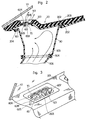
- a plate 60 is secured within each defroster outlet 70, and the plate 60 crosses the defroster outlet 70 in a direction parallel to the windshield of the vehicle.
- a plurality of bars 501 cross over the defroster outlet 70 in a direction perpendicular to the greatest extend of the dashboard 20.
- An instrument panel 209 is placed on the rear portion of the dashboard 20.
- a first duct 30, a second duct 305, a blower 306 and a heater 307 are arranged underneath the dashboard 20.
- a defroster outlet 70 is placed in the top surface 201 of dashboard 20 in the front portion thereof under the windshield 10.
- a duct 30 conveys heated air from a heater 307 to the windshield 10.
- the duct 30 has a first outlet positioned closer to the dashboard 20 than the second outlet of the duct 30.
- the plate 60 is secured within the first outlet, and the plate 60 is slanted to the right, as shown in FIG. 2.
- the plate 60 includes a rear surface 603 and a front surface 604, and the rear surface 603 faces the rear and lower portion of the vehicle.
- the rear surface 603 is defined by a bottom edge 605, a top edge 606 and two side edges 607 and 608.
- the bottom edge 605 remains below the bottom surface 202 and the top edge 606 extends slightly above the top surface 201 of dashboard 20.
- a plurality of defroster outlets 70 are arranged on the top surface 201 of the dashboard 20 and the side edges 607 and 608 of the respective plate 60 are fixed on each respective inner edge of the respective defroster duct outlet.
- the bar 501 includes two ends and an intermediate portion. The bar 501 crosses over the defroster duct outlet and the two ends of the bar 501 are fixed to the top surface 201 of the dashboard 20. The intermediate portion of the bar 501 is fixed to the top edge 606 of the plate 60 as shown in FIGS. 2 and 3.
- the dashboard 20 includes a recess 203 and a hook 204 on the bottom surface 202.
- the recess 203 is located on the central portion of the bottom surface 202 toward the rear of the vehicle and the recess 203 extends in the lateral direction of the vehicle.
- the hook 204 is located in the vicinity of the front edge of the bottom surface 202 and the hook 204 extends in the lateral direction of the vehicle.
- the first duct 30 has an upper edge which forms a first projection 301 and a second projection 302.
- the first projection 301 of the first duct 30 is mounted on the hook 204 of the dashboard 20.
- the second projection 302 of the first duct 30 is inserted into a recess 203 of the dashboard 20, so that the first duct 30 is installed easily on the bottom surface 202 of the dashboard 20.
- a sealing member 304 is provided between a lower edge 303 of the first duct 30 and a top edge of the second duct 305. This second duct 305 communicates with the heater 307.
- the heater 307 is arranged under the dashboard 20 and the heater 307 heats the air.
- a blower 306 is positioned in the vicinity of the heater 307 and the blower 306 distributes heated ,air to the defroster outlet 70 of the dashboard 20 through the second duct 305 and the first duct 30.
- the heated air hits the rear surface 603 of the plate 60 and the blowing direction of the heated air is controlled by the direction of the plate 60.
- Most of the heated air is discharged in the direction defined by the rear surface 603 of the plate 60, and most of the heated air is concentrated on a specific area of the windshield 10.
- the remainder of the heated air strikes around the specific area of the windshield 10 and then flows along an inside surface across of the entire windshield 10.
- the heated air effectively removes frost or moisture from the entire of the inside surface of the windshield 10.
- the windshield defroster includes a bar 501 and a plate 60 placed within the defroster outlet 70, so that bar 501 and plate 60 prevent an object from dropping into the defroster outlet 70.
- Our EPC Application (Ref: TTS 84-EPC-021H/LBN) is filed in the European Patent Office contemporaneous with this application and entitled "A WINDSHIELD DEFROSTER ASSEMBLY".
- the EPC Application discloses a windshield defroster having a particular screen arrangement for a defroster outlet. Such a screen arrangement can be included in the embodiments of the present invention.
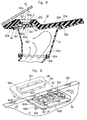
- FIGS. 4 and 5 show a windshield defroster of a second embodiment. While most of the components in the second embodiment are the same as the components previously described above for the first embodiment, the second embodiment has several differences.
- a dashboard 20 has a plurality of inner peripheral edges defining defroster outlet 70.
- a screen 50 is positioned in the vicinity of the defroster outlet 70 and under a bottom surface 202 of the dashboard 20.
- the screen 50 includes an inner peripheral edge, a plurality of bars 501 and a plate 60.
- Each bar 501 has two ends.
- the inner peripheral edge of the screen 50 defines an opening 502.
- Each end of each of the plurality of bars .501 and the sides 607 and 608 of the plate 60 is secured to the inner peripheral edge of the opening 502.
- the bar 501 is positioned so that it is perpendicular to the top edge 606 of the plate 60 and an intermediate portion of the bar 501 is fixed onto the top edge 606 of the plate 60.
- An upper surface of the screen 50 faces the bottom surface 202 of the dashboard 20 with a space therebetween, and the opening 502 of the screen 50 communicates or is congruent with the defroster outlet 70.
- a front edge of the screen 50 is connected to the first projection 301 of a duct 30 through an integral hinge 40.
- the screen 50 may rotate about the front edge of the first projection 301 of the duct 30.
- the plate 50 still controls the direction of discharge of the heated air.
- the screen 50 may be fixed securely on the bottom surface 202 of the dashboard, or the front edge of the screen 50 may be fixed securely on the first projection 301 of the duct 30.
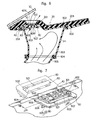
- FIGS. 6, 7 and 8 disclose a windshield defroster of a third embodiment. While most of the components in the third embodiment are the same as the components previously described above for the second embodiment, the third embodiment has several differences.
- a screen 50 includes an inner peripheral edge to which a rudder 60 and a plurality of bars 501 are attached.
- the inner peripheral edge of the screen 50 defines an opening 502, and the inner peripheral edge of the screen 50 contains a pair of cavities 504 which face each other.
- the rudder 60 has a hinge pins 602 on both sides 607 and 608 thereof. Each of the hinge pins 602 are inserted into a respective cavity 504, and the hinge pins 602 lie on the axis of the rudder 60. Therefore, the rudder 60 can rotate about the axis of the rudder 60 within the opening 502 of the screen 50.
- the bar 501 crosses over the opening 502 of the screen 50 and each end of the bar 501 fixed on the inner peripheral edge of the screen 50.
- the bar 501 is positioned so that it is perpendicular to the top edge 606 of the rudder 60, and an intermediate portion of the bar 501 crosses over the top edge 606 of the rudder 60.
- the intermediate portion of the bar 501 is positioned within the defroster outlet 70 in dashboard 20, such that the bar 501 does not prevent the rudder 60 from rotating within the opening 502 of the screen 50.
- the top edge 606 of the rudder 60 is disposed slightly under the top surface 201 of the dashboard 20, so that an operator can manually rotate the rudder 60 through the defroster outlet 70.
- the direction of discharge of the heated air can be changed easily by changing the orientation of the rudder 60.
- the windshield defroster according to the present invention can remove more effectively frost or moisture from the entire inside surface of the windshield 10. This is a significant improvement over known defroster assemblies.
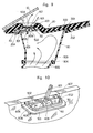
- FIGS. 9 and 10 show a windshield defroster of a fourth embodiment. While most of components in the fourth embodiment are the same as the components previously described above for the third embodiment, the fourth embodiment has several differences.
- a rudder 60 has a stick 601 which is secured to the top edge 606 of the rudder 60.
- the top end of the stick 601 projects over the top surface 201 of a dashboard 20, so that an operator can easily rotate the rudder 60. Further rotation of the rudder 60 is prevented by the intermediate portion of the stick 601 contacting the inner peripheral edge of the defroster outlet 70.
- Each of the embodiments described above illustrates a windshield defroster of the present invention which effectively removes frost or moisture from the entire windshield surface of a vehicle without impairing the vision of a driver through the windshield.
Landscapes
- Engineering & Computer Science (AREA)
- Mechanical Engineering (AREA)
- Physics & Mathematics (AREA)
- Thermal Sciences (AREA)
- Air-Conditioning For Vehicles (AREA)
Applications Claiming Priority (4)
| Application Number | Priority Date | Filing Date | Title |
|---|---|---|---|
| JP6567584U JPS60176912U (ja) | 1984-05-03 | 1984-05-03 | デフロスタ風向き調整装置 |
| JP65675/84U | 1984-05-03 | ||
| JP14504884A JPS6124652A (ja) | 1984-07-12 | 1984-07-12 | デフロスタ風向き変更装置 |
| JP145048/84 | 1984-07-12 |
Publications (3)
| Publication Number | Publication Date |
|---|---|
| EP0161839A2 true EP0161839A2 (fr) | 1985-11-21 |
| EP0161839A3 EP0161839A3 (en) | 1987-04-01 |
| EP0161839B1 EP0161839B1 (fr) | 1989-06-28 |
Family
ID=26406811
Family Applications (1)
| Application Number | Title | Priority Date | Filing Date |
|---|---|---|---|
| EP85302840A Expired EP0161839B1 (fr) | 1984-05-03 | 1985-04-23 | Ensemble de dégivrage de pare-brises |
Country Status (3)
| Country | Link |
|---|---|
| US (1) | US4637298A (fr) |
| EP (1) | EP0161839B1 (fr) |
| DE (1) | DE3571228D1 (fr) |
Cited By (1)
| Publication number | Priority date | Publication date | Assignee | Title |
|---|---|---|---|---|
| FR2590526A1 (fr) * | 1985-11-22 | 1987-05-29 | Daimler Benz Ag | Dispositif d'aeration pour l'habitacle d'un vehicule automobile |
Families Citing this family (12)
| Publication number | Priority date | Publication date | Assignee | Title |
|---|---|---|---|---|
| US5787228A (en) * | 1996-02-28 | 1998-07-28 | Fiely; Sharon K. | Portable vehicle articulated windshield defroster with heated air-flow and timer |
| JP3580539B2 (ja) * | 2000-10-18 | 2004-10-27 | 本田技研工業株式会社 | 空調用ダクト及び空調用ダクトの製造・取付方法 |
| EP1454780A3 (fr) * | 2003-03-03 | 2006-02-15 | TRW Automotive Electronics & Components GmbH & Co. KG | Buse d'aération pour une installation de ventilation |
| US7562912B2 (en) * | 2006-02-07 | 2009-07-21 | Toyota Motor Engineering & Manufacturing North America, Inc. | Duct mating assembly |
| FR2909935B1 (fr) * | 2006-12-19 | 2015-04-24 | Renault Sas | Dispositif de climatisation d'un vehicule comportant un reseau de canalisations de degivrage |
| US8109812B2 (en) * | 2007-12-14 | 2012-02-07 | Toyota Motor Engineering & Manufacturing North America, Inc. | Motor vehicle instrument panel assembly having a conduit with a gasket support lip |
| ATE481256T1 (de) * | 2008-07-31 | 2010-10-15 | Fiat Ricerche | Motorfahrzeug-armaturenbrett mit hauptzentrale und ausgabeöffnungen für die belüftungsluft |
| JP6361221B2 (ja) * | 2014-03-27 | 2018-07-25 | 株式会社デンソー | 空気吹出装置 |
| US9603200B1 (en) * | 2015-02-03 | 2017-03-21 | Camille Bennett | Portable windshield defroster |
| US10787154B2 (en) * | 2016-09-07 | 2020-09-29 | Ford Global Technologies, Llc | Windshield defroster with secondary ducted outlet |
| CN115923720A (zh) * | 2022-12-01 | 2023-04-07 | 北京集度科技有限公司 | 除霜/除雾系统、控制方法、交通工具及计算机程序产品 |
| US20250136050A1 (en) * | 2023-10-26 | 2025-05-01 | Dale Boegeman | Duct for directing warm air toward a windshield wiper |
Family Cites Families (15)
| Publication number | Priority date | Publication date | Assignee | Title |
|---|---|---|---|---|
| US2894443A (en) * | 1956-06-25 | 1959-07-14 | Gen Motors Corp | Multiple passage supply duct |
| DE1869272U (de) * | 1961-12-14 | 1963-03-21 | Nsu Motorenwerke Ag | Regeleinrichtung fuer eine frisch- und heizluftzufuehrung von kraftfahrzeugen. |
| US3524044A (en) * | 1966-06-27 | 1970-08-11 | Vincent L Liardi | Deicing apparatus |
| US3472146A (en) * | 1967-08-11 | 1969-10-14 | Ford Motor Co | Fluid pressurizing and distributing apparatus for vehicles |
| US3456572A (en) * | 1967-12-18 | 1969-07-22 | Ford Motor Co | Vehicle panel assembly |
| FR2029876A5 (fr) * | 1969-01-29 | 1970-10-23 | Peugeot & Renault | |
| US3608469A (en) * | 1969-05-12 | 1971-09-28 | Toyoda Chuo Kenkyusho Kk | Apparatus for the removal of dewdrops from a dewed plate member |
| DE2230776A1 (de) * | 1972-06-23 | 1974-01-10 | Siempelkamp Gmbh & Co | Anlage zur herstellung von spanplatten, faserplatten und dergl |
| US3927607A (en) * | 1973-08-11 | 1975-12-23 | Gen Motors Corp | Defroster outlet |
| FR2401038A2 (fr) * | 1976-07-12 | 1979-03-23 | Ferodo Sa | Dispositif d'aerateur pour habitacle d'automobile |
| JPS5516747Y2 (fr) * | 1977-04-01 | 1980-04-18 | ||
| US4105246A (en) * | 1977-06-20 | 1978-08-08 | Trumbull Gerald M | Multi-purpose dashboard attachment |
| JPS5531652A (en) * | 1978-08-30 | 1980-03-06 | Nissan Shatai Co Ltd | Blow-off grille at upper part of dashboard |
| DE2847678C2 (de) * | 1978-11-03 | 1982-05-19 | Daimler-Benz Ag, 7000 Stuttgart | Aus Zwei Halbschalen mit durchgehender Trennungsebene bestehende Luftaustrittsvorrichtung |
| JPS58174049A (ja) * | 1982-04-07 | 1983-10-13 | Nissan Motor Co Ltd | 車両用デフロスタ装置 |
-
1985
- 1985-04-18 US US06/724,545 patent/US4637298A/en not_active Expired - Fee Related
- 1985-04-23 DE DE8585302840T patent/DE3571228D1/de not_active Expired
- 1985-04-23 EP EP85302840A patent/EP0161839B1/fr not_active Expired
Cited By (1)
| Publication number | Priority date | Publication date | Assignee | Title |
|---|---|---|---|---|
| FR2590526A1 (fr) * | 1985-11-22 | 1987-05-29 | Daimler Benz Ag | Dispositif d'aeration pour l'habitacle d'un vehicule automobile |
Also Published As
| Publication number | Publication date |
|---|---|
| DE3571228D1 (en) | 1989-08-03 |
| EP0161839B1 (fr) | 1989-06-28 |
| EP0161839A3 (en) | 1987-04-01 |
| US4637298A (en) | 1987-01-20 |
Similar Documents
| Publication | Publication Date | Title |
|---|---|---|
| EP0161839A2 (fr) | Ensemble de dégivrage de pare-brises | |
| US4610196A (en) | Air supply nozzle | |
| KR900000518B1 (ko) | 방풍유리 서리제거장치의 구조 | |
| US4604946A (en) | Structure of defroster nozzle for automotive vehicle | |
| US4583448A (en) | Windshield defroster | |
| US20100062702A1 (en) | Defroster nozzle | |
| KR0139841B1 (ko) | 차량 실내용 통풍노즐 | |
| EP0073317B1 (fr) | Caisson-traverse de tablier de véhicule à moteur | |
| EP0161087B1 (fr) | Ensemble de dégivrage de pare-brises | |
| JP3855588B2 (ja) | ダクトの吹出口部構造 | |
| KR19980025510U (ko) | 윈드 실드 글래스의 서리 제거장치 | |
| JPS6325255Y2 (fr) | ||
| JP3741082B2 (ja) | デフロスタノズル | |
| JP3721816B2 (ja) | デフロスタノズル取付構造 | |
| KR200141380Y1 (ko) | 자동차의 디프로스터 송풍구 개폐장치 | |
| KR0125108Y1 (ko) | 성애제거용 보조그릴 | |
| JPH0236726Y2 (fr) | ||
| KR0126705Y1 (ko) | 자동차용 릴레이 박스 | |
| KR19980016550U (ko) | 자동차의 공조장치용 에어벤트구조 | |
| KR0126602Y1 (ko) | 자동차의 대쉬패널 구조 | |
| JPH0495551A (ja) | 風向可変式デフロスタノズル | |
| KR0142235B1 (ko) | 도어의 그릴 디프로스터 구조 | |
| JP2005153700A (ja) | 車両用デフロスタ装置 | |
| KR200154279Y1 (ko) | 자동차 통풍구 유니트 조립구조 | |
| KR19990034548A (ko) | 자동차의 그릴 벤틸레이터 |
Legal Events
| Date | Code | Title | Description |
|---|---|---|---|
| PUAI | Public reference made under article 153(3) epc to a published international application that has entered the european phase |
Free format text: ORIGINAL CODE: 0009012 |
|
| AK | Designated contracting states |
Designated state(s): DE FR GB |
|
| 17P | Request for examination filed |
Effective date: 19860613 |
|
| PUAL | Search report despatched |
Free format text: ORIGINAL CODE: 0009013 |
|
| AK | Designated contracting states |
Kind code of ref document: A3 Designated state(s): DE FR GB |
|
| 17Q | First examination report despatched |
Effective date: 19871215 |
|
| GRAA | (expected) grant |
Free format text: ORIGINAL CODE: 0009210 |
|
| AK | Designated contracting states |
Kind code of ref document: B1 Designated state(s): DE FR GB |
|
| REF | Corresponds to: |
Ref document number: 3571228 Country of ref document: DE Date of ref document: 19890803 |
|
| ET | Fr: translation filed | ||
| PLBE | No opposition filed within time limit |
Free format text: ORIGINAL CODE: 0009261 |
|
| STAA | Information on the status of an ep patent application or granted ep patent |
Free format text: STATUS: NO OPPOSITION FILED WITHIN TIME LIMIT |
|
| 26N | No opposition filed | ||
| PGFP | Annual fee paid to national office [announced via postgrant information from national office to epo] |
Ref country code: GB Payment date: 19910415 Year of fee payment: 7 |
|
| PGFP | Annual fee paid to national office [announced via postgrant information from national office to epo] |
Ref country code: FR Payment date: 19910426 Year of fee payment: 7 |
|
| PGFP | Annual fee paid to national office [announced via postgrant information from national office to epo] |
Ref country code: DE Payment date: 19910531 Year of fee payment: 7 |
|
| PG25 | Lapsed in a contracting state [announced via postgrant information from national office to epo] |
Ref country code: GB Effective date: 19920423 |
|
| GBPC | Gb: european patent ceased through non-payment of renewal fee | ||
| PG25 | Lapsed in a contracting state [announced via postgrant information from national office to epo] |
Ref country code: FR Effective date: 19921230 |
|
| PG25 | Lapsed in a contracting state [announced via postgrant information from national office to epo] |
Ref country code: DE Effective date: 19930101 |
|
| REG | Reference to a national code |
Ref country code: FR Ref legal event code: ST |