EP0161938B1 - Mécanisme d'extension et de rétraction d'antenne - Google Patents
Mécanisme d'extension et de rétraction d'antenne Download PDFInfo
- Publication number
- EP0161938B1 EP0161938B1 EP85303440A EP85303440A EP0161938B1 EP 0161938 B1 EP0161938 B1 EP 0161938B1 EP 85303440 A EP85303440 A EP 85303440A EP 85303440 A EP85303440 A EP 85303440A EP 0161938 B1 EP0161938 B1 EP 0161938B1
- Authority
- EP
- European Patent Office
- Prior art keywords
- wire
- drum
- antenna
- motor
- clutch
- Prior art date
- Legal status (The legal status is an assumption and is not a legal conclusion. Google has not performed a legal analysis and makes no representation as to the accuracy of the status listed.)
- Expired - Lifetime
Links
Images





Classifications
-
- H—ELECTRICITY
- H01—ELECTRIC ELEMENTS
- H01Q—ANTENNAS, i.e. RADIO AERIALS
- H01Q1/00—Details of, or arrangements associated with, antennas
- H01Q1/08—Means for collapsing antennas or parts thereof
-
- H—ELECTRICITY
- H01—ELECTRIC ELEMENTS
- H01Q—ANTENNAS, i.e. RADIO AERIALS
- H01Q1/00—Details of, or arrangements associated with, antennas
- H01Q1/08—Means for collapsing antennas or parts thereof
- H01Q1/10—Telescopic elements
- H01Q1/103—Latching means; ensuring extension or retraction thereof
Definitions
- This invention relates to a mechanism for extending and contracting (meaning “retracting") an antenna, and more particularly a mechanism for manually or automatically extending and contracting an antenna, for example a telescope type antenna.
- telescope type antenna is constituted by a plurality of tubes having different diameters which are interconnected like a telescope.
- the antenna is extended or contracted by using a wire which does not expand and contract.
- the wire utilized for this purpose has a circular cross-sectional configuration. It is advantageous that the wire is straight when the antenna is extended.
- a synthetic resin for example a polyacetal resin, is suitable to form an operating wire having a circular cross-section.
- a gear is used for extending and contracting the operating wire.
- the gear is situated at a wire passing port provided for a casing containing a drum or at a position just below an antenna base cylinder mounting portion.
- the gear is driven by an electric motor and a rack is provided for engaging the gear.
- Special constructions for driving the gear are disclosed in Japanese Utility Model Laid Open Patent Specification No . 49,942/1976, 155,033/1977 and 36,613/ 1979.
- a strip member or the like is substituted for a wire driven by the gear, and perforations are provided for the strip member for engaging the gear.
- Japanese Laid Open Patent Specification No. 29,047/1978 discloses a plastic belt clamped between rollers to be extended and contracted by driving the rollers.
- a gear is formed on peripheral of a large diameter pulley contained in a casing, and driven by an electric motor, and a wire push member is provided in a range of 90° in the peripheral direction of said pulley starting from a position immediately beneath an antenna base cylinder, that is an antenna receiving cylinder. Furthermore, a rack is formed on one side of said wire so as to mesh the rack with the gear provided for the pulley.
- This reference also shows a construction wherein the rear surface of the wire push member is made flat so as to efficiently guide the wire push member.
- Japanese Utility Model Laid Open Patent Specification No. 31,044/1981 discloses a flat rectangular wire which is substituted to a conventional wire having a circular corss-section for the purpose of neatly accommodating an antenna operating wire in a casing. Since this wire is intended to substitute for a conventional circular wire, its cross-sectional configuration is approximately square.
- the extending and contracting antenna is frequently used in motor cars.
- Such car mounted antenna is extended and contracted by manual operation or automatic operation utilizing an electric motor.
- the manual operation has been used for many years.
- the antenna can be extended and contracted by operating a switch installed in a car.
- the driver may often get out of the car without contracting the antenna. In such a case, the driver must enter again into the car for operating a switch so as to contract the antenna.
- various proposals have been made. For example, where a multithread worm is used it can be driven by manual operation and an electric motor. According to another proposal, a planet wheel mechanism which is controlled by an electromagnet for extending and contracting the antenna.
- an antenna operating member is made of a noncontractive linear synthetic resin wound about a rotary drum.
- the antenna is extended and contracted by the rotation of the drum through the antenna operating member. Accordingly, not only the drum diameter is increased but also the resistance to paying out and taking up of the antenna operating element having a relatively large resistance is increased. For this reason, the size of the antenna extending and contracting mechanism is determined by the diameter of the drum, meaning an increase in the capacity of the motor.
- the wire is payed out while being strongly urged against the inner surface of the drum or the surface of the winding groove (which is arcuate for receiving the wire having circular cross-section). But the wire tends to slide along the inner surface of the drum or of the winding drum, while inclining thereto.
- the pay out efficiency caused by a push force decreases substantially.
- Slipping of the wire while being urged against the inner surface of the drum or the surface of the winding groove means pushing out the wire from the rotatably mounted drum toward a stationary base member which causes the periphery of the drum to move away from the base member.
- the wire would be pushed in between the drum and the base member like a wedge, thus disenabling the rotation of the drum in either direction.
- the wire would be twisted helically in an opening through the antenna base cylinder, thus breaking the wire.
- the operating wire disclosed in Japanese Laid Open Utility Model Specification No. 31,044/1981 has substantially square cross-section. Although it can be neatly taken up in a drum, in the taken up state, the wire tends to bend in the circumferential direction of the drum so that the taken up state of the wire is not always stable. Accordingly, the push up force of the antenna and the extending and contracting characteristics are similar to a circular wire whereby smooth take up and miniaturization of the mechanism are difficult.
- US-A-3 253 799 discloses apparatus comprising an antenna, constituted by a plurality of telescoped antenna sections, and an antenna-extending and retracting mechanism including a rotary drum for taking-up and paying-out a relatively rigid wire so as to extend and retract said antenna, an electric motor for driving said drum, an antenna base cylinder for accommodating said antenna sections when the antenna is retracted, a base member supporting said drum, and clutch means incorporated into a motion transmission system between said motor and said drum, one end of said wire being connected to an uppermost antenna section through said antenna base cylinder, and guide means interposed between said antenna base cylinder and said drum.
- the wire is round and therefore liable to twist.
- US-A-2 989 259 discloses an automatically operated radio antenna with telescoping antenna sections which are extended and retracted by a "strip (18)", the cross-section of which is not specifically described and cannot be accurately determined from the drawings, because Fig. 4, showing an unreferenced section through the strip 18, is a horizontal section (on line 4-4 of Fig. 1) and the angle of the strip 18 to the horizontal is unknown.
- Another object of this invention is to provide an improved antenna extending and contracting mechanism including a clutch enabling to contract and extend the antenna by an electric motor or a man power.
- the invention is characterized by an antenna operating wire utilized to extend and contract the antenna.
- the wire 1 is made of such hard synthetic resin as polyacetal resin which does not expand or contract and becomes straight when released.
- the wire has a rectangular or similar cross-sectional configuration having a width W and a thickness t.
- the side surfaces 13 between opposing flat surfaces 12 or 12a may be arcuate.
- the wires shown in Figs. 1A and 1B have flat surfaces while the wires shown in Figs. 1C and 1D have slightly convex surfaces 12a.
- the width of the wire should be large such that the arcuate side portions 13 will make intimate contacts with the inner surface of the base cylinder 7 of the antenna, or that the interfaces between the flat surfaces 12 or 12a and the arcuate side portions 13 would make line contact against the inner surface of the antenna base cylinder in the axial direction of the wire 1.
- the surfaces 12 are slightly convex as shown by 12a in Figs. 1C and 1D, extraction of the wire 1 becomes easy.
- the radius of the Convex surface should not be smaller than the radius of the inner surface of the base cylinder 7.
- the flat surfaces 12 and the slightly convex surfaces 12a are not required to be always smooth and may be slightly irregular.
- a plurality of telescoped tubular antenna sections 9a - 9n are made of metals and have different diameters. When extended these sections constitute a multisection transmitting or receiving antenna. All of these antenna sections are accommodated in the antenna base cylinder 7 when they are contracted. Of course, the inner diameter of each antenna section is smaller than that of the antenna base cylinder 7.
- Such single line contact requires stronger push out force, and a wire which bends in any arbitrary direction is caused to readily slide in the lateral direction by a force applied after the antenna has completely been extended, whereby the wire would bend wavy or spirally in the antenna base cylinder.
- Such bending of the wire in the antenna sections greatly reduces the push out force.
- Such decreased push out force merely acts as a bending force of the wire, thus degrading and breaking the wire.
- the central portion 0 of the wire may take the form of a small opening 11 as shown in Figs. 1B and 1 D.
- the antenna operating wire 1 is taken up or wound about a drum shaped take-up rotary drum 2.
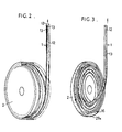
- the wire can be taken up spirally as shown in Fig. 3 or helically as shown in Fig. 2.
- the wire taken up in this manner is contained in a casing 3 shown in Fig. 4 or 5 and the drum is rotated by an electric motor 4.
- the take-up drum 2 is secured coaxially with a motor driven worm wheel 5 and rotated integrally with the worm wheel 5 by the pressure applied by a clutch mechanism 6. As the pressure applied by the clutch mechanism is released, only the worm wheel 5 rotates.
- the wire 1 extends into the antenna base cylinder 7 and is connected to the uppermost one of the antenna sections having different diameters, so as to extend and contract the antenna sections by the forward and reverse rotation of the motor.
- a guide member which guides the wire into the take-up drum while spirally or helically bending the wire.
- the guide member is provided with an inclined guide surface 31 on the side of the take-up drum 2 and a groove 32 formed at the central portion of the inclined guide surface 31 for receiving one end of the flat wire 1. Since annular wire receiving groove 29 is provided for the inner periphery of the take-up drum 2 the groove 29 can receive the other end of the flat wire 1.
- the groove 29 has the same width as the groove 32, being wide enough for the required number of widthwise side-by-side turns of the wire 1, and just high enough for the thickness t of each turn.
- the flat surfaces 12 are not in any specific direction, but as the leading end of the wire 1 is bent toward the wire receiving groove 29 by the inclined guide surface, due to the large resistance to the bending in the direction of the width of the wire, the bending of the wire is limited to its thickness direction so that one of the flat surfaces 12 would be received in the receiving groove 29 while the other in the receiving groove 32. Since the flat surfaces 12 are parallel to the periphery of the take-up drum 2, the above described guide operation makes easy helical winding of the wire.
- the wire 1 is made of polyacetal resin, for example, the wire tends to slip on the inclined guide surface 31 and in the receiving groove 29 of the take-up drum 2 and the result of experiment shows that the receiving of the leading end of the wire can be smoothly effected. Once the leading end is correctly received, pay out and take up of the wire from and onto the rotary drum can be effected neatly and smoothly.
- a ball 16 is secured to the leading end of the wire 1, and a circular enlarged groove 29a shown by dotted lines in Fig. 11 is formed at one portion of the receiving groove 29 to extend in the direction of the depth thereof, that is the width direction of the take-up drum.
- the engaging member slides along the inclined guide surface 31 to reach the entrance of the circular enlarged groove 29a.
- the wire 1 is bent in its thickness direction, and moreover since one of the flat surfaces 12 engages the opening end of the receiving groove of the take-up drum 2, the rolling of the engaging member becomes easy, whereby the reception of the flat wire in the receiving grooves 29 and 32 becomes more smooth, the ball 16 received in the enlarged groove 29a is pushed into a deep portion as the amount of the wire taken up increases with the result that the entire length of the wire 1 can be neatly received as a helix in the receiving groove 29 as shown in Fig. 4.
- a thickness to width ratio of 1.5 - 2.2 is advantageous for a flat operating wire made of polyacetal resin or the like.
- this ratio is less than 1.5, where the wire has an elliptical sectional configuration as shown in Figs. 1 C and 1 D.
- the advantage of flat wire that the direction of bending is specified can not be attained.
- the thickness to width ratio exceeds 2.2, the wire become a strip or tape so that its antenna section push out force decreases. In other words, when applied with the push out force, the wire tends to bend in complicated shape, thus losing the property of a rigid wire. Provision of an opening at the central portion of the wire does not affect the push out force of the wire so long as the radius of the opening is less than several % of the radius of the opening.
- Figs. 7A, 7B, Figs. 8A, 8B and 8C show the relation between the cross-sectional configuration of the wire and the multi-section antenna.
- one end of wire 1 is connected to the uppermost section 9a of the antenna sections 9a, 9b ... 9n.
- the uppermost section 9a is telescopely received in the second and succeeding sections.
- Fig. 8A shows a cross-sectional view utilizing a prior art or circular wire 1.
- the gap 19 between the wire 1 and the second antenna section 9b is relatively large
- Figs. 9B and 9C utilizing a flat wire 1 of this invention, the gap 19a between the arcuate ends 13 of the wire and the second antenna section 9b is very small.
- the cross-sectional area (or diameter) of the wire is limited by the inner diameter of the second antenna section 9b.
- the inner diameter of the second antenna section 9b generally lies in a range of 4.3 - 4.5 mm so that the diameter or width of the wire 1 can not exceed the inner diameter of the second section.
- the load necessary for bending the flat wire of this invention having a width to thickness ratio of 1.5 in a direction parallel to flat surface amounts to about 3 times of the load necessary for bending a prior art round wire (shown in Fig. 8A) having a diameter of about 4 mm, made of polyacetal resin and bent with a radius of 4 cm. Such multiplying factor increases with the degree of flatness.
- the flat wire of this invention is received between supporting walls 2b provided for the take-up drum 2. Since the wire 1 is flat, in each of the cases shown in Figs. 2 - 6, the gap between adjacent supporting walls 2b is relatively narrow.
- the flat surfaces 12 engage the supporting walls 2b, whereas at the time of pushing out the antenna sections, the flat surfaces engage the supporting walls on the radially inner wall.
- the flat surfaces engage the supporting walls on the radially inner side.
- the flat surfaces stably engages the supporting walls 2b and do not accompany slips along inclined surfaces which occurs when the wire has a circular cross-section. Consequently as shown in Figs.
- the clutch mechanism (shown in Fig. 5) incorporated between the worm wheel 5 and the take-up drum 2 in the base member 3 comprises a clutch plate 69 resiliently urged by a resilient member 96 against the take-up drum 2 rotatably supported by the base member 3.
- a projection 69a on the periphery of the clutch plate 69 engages a projection 23 provided for the take-up drum 2.
- the clutch plate 69 is mounted on a square shaft 55 of a worm wheel (not shown) meshing with worn 44 driven by an electric motor. Consequently, in a case wherein the take-up drum 2 is stopped when the shaft 55 of the worm wheel is rotated with a force larger than a predetermined clutch force, projection 69a disengages from projection 23, thus releasing the clutch.
- the square shaft 55 and a threaded shaft 55a integral therewith are formed with an inner bore to receive a mounting shaft of the base member 3 for mounting a cover member 9.
- a special clutch mechanism and elements associated therewith which are suitable for extending and contracting the antenna by utilizing the characteristics of the wire are shown in Figs. 4, 11, 6 and 12. More particularly, a shaft 34 is secured to the central portion of the base portion 3 and the mounting seat 37 of the antenna base cylinder 7 and the mounting seat 36 of the motor 4 are provided for the upper portion of the base member 3, and a small worm wheel 35 meshing with the worm wheel 5 is secured to the lower surface of the mounting seat 36. A worm 44 driven by motor 4 meshes with the worn wheel 5. Where a small motor 4a is secured to the mounting seat 36 instead of motor 4, a worm 44a driven by the small motor 4a drives the worm wheel 5 via a small worm wheel 35.
- the worm wheel 5 can be driven efficiently.
- the weight of the motor 4 is the maximum so that when a small motor 4a is used the weight of the mechanism can be reduced substantially.
- the clutch mechanism utilized in this invention will now be described with reference to Figs. 4 and 11.
- the mounting shaft 34 is received in an opening 50 provided for the worm wheel 5 and the shaft 51 thereof.
- Engaging surfaces are formed on one end of shaft 51 for engaging with the engaging surfaces 82 provided for an opening 80 of a rotating member 8 (to be described later) so as to be slidable in the axial direction but to rotate integrally.
- the shaft opening 20 of the take-up drum 2 is fitted on the base end of the shaft 51.
- the rotary member 8 and the clutch member 6 are amounted on the engaging surfaces 52 in a chamber 27 on the inside of the receiving groove 29 of the take-up drum thus fitted.
- circular shaft openings 60 are provided for the rectangular clutch member 6.
- An opening 61 for receiving the rotary member 8 is defined between opposing sides of the clutch member 6.
- the substantially rectangular rotary member 8 is assembled to cross the clutch member 6.
- the engaging surfaces 82 of an opening 80 for receiving the rotary member 8 are caused to engage the engaging surfaces 52 so as to transmit the torque of the worm wheel 5 to the rotary member 8.
- Valley shaped cams 84 are formed at the centers of the side surfaces of the rotary member 8 and inclined engaging portions 85 adapted to engage projections 66 on the upper and lower sides of the shaft opening 60 of the clutch member 6 are formed on both sides of the valley shaped cams 84.
- the shorter end surfaces of the clutch member 6 are provided with opposing openings 62 in which a pair of engaging members 64 and 65 interconnected through a coil spring 63 are fitted respectively.
- the inner members 65 are received in the valley shaped cams 84, while the outer members 64 are caused to engage and disengage a plurality of recesses formed on the side surface of the chamber 27 of the drum.
- a washer 14 and a E ring 15 are mounted on the shaft 34 of the base member 3 mounted with the worm wheel 5, the take-up drum 2, the clutch member 6 and the rotary member 8 and a leaf spring 68 is caused to engage inclined portions 67 formed on the opposite surfaces of the clutch member 6.
- a frictional force of the leaf spring 68 created by a nut 33 (see Fig. 4) threaded on the shaft 34 is applied between the clutch member 6 and the take-up drum 2 so as to make different the rotations of the rotary member 5 and the clutch member 6.
- the clutch mechanism described above can also be applied to a take-up drum which spirally takes up the wire as shown in Figs. 3 and 6. More particularly, a spiral wire receiving groove 24 is formed on one surface of a plate shaped rotary member 2 and an annular projection 28 is formed on the other side of the rotary member 2 to define a chamber 27 for receiving the clutch member 6, and the rotary member 8 in the same manner as that shown in Fig. 4.
- a partition plate 26 having a center opening 26a for passing the shaft is disposed between the base member 3 and the take-up drum 2 at the opening of the spiral wire receiving groove 24.
- the partition plate 26 is formed with a radially extending wire admitting notch 25 over the entire range in which the wire receiving groove 24 is formed.
- one end of wire 1 led from the antenna base cylinder 7 is connected to the drum 2 through the notch 25.
- a switch mechanism may be provided for automatically controlling the motor.
- Such switch mechanism is designated by 96 in Fig. 11 and provided with a rotary member 93 in the form of a gear 93 that engages projections 53 on the rear surface of the worm wheel 5.
- As the gear shaped rotary member 93 intermittently rotates by engaging the projections 53 so as to transmit the rotation of the worm wheel 5 imparted by motor 4 to the switch mechanism 90 for ON'OFF controlling the stop signal of the motor 4.
- Such mechanism can be used for a case wherein the antenna is extended and contracted by the operation of a car ignition switch (that is an engine switch) or a radio switch and the motor is stopped at the limits of extension and contraction of the antenna.
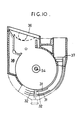
- the construction of the extending and contracting mechanism including the motor can be made compact, the base member thereof being shown in Fig. 10.
- the diameter of the take-up drum 2 can be made small.
- the motor mounting seat 36 formed at one side of the upper portion of the base member 3 is inclined toward the other side of the base member so that the motor 4 or 4a mounted on such mounting seat 36 inclines towards the antenna base cylinder as shown in Fig. 12, whereby the motor 4 is mounted in the reduced diameter range of the base member 3.
- An inner space 38 in the mounting space 36 can be formed by stamping the base portion 3 formed integrally at right angles with respect to a reference surface of the base member 3, for example the mounting surface 37 of the antenna base cylinder. Since the motor 4 is positioned in a range of the diameter of the reduced diameter base member 3, the construction of the automatic antenna extending and contracting mechanism can be made to be compact, thereby facilitating the mounting of the mechanism on a car, which also decreases the volume of the packed mechanism. Generally stated, in the mechanism of this type, a portion having a length nearly equal to the radius of the motor projects beyond the range of the diameter of the base member 3. For example, in Fig. 12A when worm 44 is caused to engage worm wheel 5 on the outside thereof and in a vertical position, a portion of the motor 4 nearly equal to the radius thereof will project to the outside of the base portion.
- the clutch mechanism shown in Figs. 4, 11 and 6 operates as follows.
- the engaging member 65 In a stationary state in which the torque of the worm is not transmitted to the worm wheel 5, its shaft 51, and the rotary member 8, the engaging member 65 is positioned at an intermediate portion of the valley shaped cam 84.
- the coil spring 63 is not compressed to any appreciable extent so that the engaging member 64 is disengaged from the recess 21 of take-up drum 2 as shown by a portion above the shaft 34 shown in Fig. 4.
- the drum 2 can rotate independantly of the clutch member 6 and the rotary member 8.
- the clutch mechanism shown in Figs. 4, 11 and 6 it is possible to readily release the clutch for facilitating manual extension and contraction at the beginning thereof, the clutch mechanism being indispensable for stopping the take-up drum at the time of automatically extending and contracting the antenna.
- the extended antenna can be manually contracted for facilitating the car washing.
- the driver can get out of the car to contract the antenna.
- the engaging member 64 is always pressed into the recess 21 by spring 63.
- the antenna can be extended or contracted.
- Guide means for taking up the wire between the antenna base cylinder and the take-up drum with the thickness direction of the wire oriented in the radial direction of the take-up drum not only provides an advantageous guide function to the wire at the time of extracting the antenna but also a desirable contact resistance when the extended antenna tends to contract due to the vibration of the car.
- the surface of the bent or inclined guide means produces a friction for the wire, thereby preventing contraction of the extended antenna.
- connection between the upper end of the wire 1 and the uppermost antenna section 9a permits free exchange of the antenna together with the engagement of the spherical portion 16 at the lower end of the wire 1 (see Fig. 11) with circular enlarged groove 38 as well as the sliding of the wire along the groove 38.
- the antenna sections 9a - 9n can be exchanged in the same manner.
- the antenna can be pushed out without causing the wire 1 to twist helically in the antenna base cylinder 7, so that the antenna sections 9a - 9n can be extracted and contracted in proportion to the amount of rotation of the worn wheel 5 or motor 4, thereby decreasing the load thereof.
- the switch is opened and the clutch is released to stop the motor when the antenna has been completely contracted or extended so that it has been prohibited to release the clutch or to open the switch before complete extension of the antenna because there is a large probability that the motor is stopped before complete extension of the antenna. Under this condition, the wire 1 is twisted helically.
- the amount of rotation of the motor or the worm wheel is directly proportional to the amount of extension and contraction of the antenna so that the tendency of twisting the wire in the antenna base cylinder can be prevented and it is possible to forecast the time of complete extension and contraction based on the amount of rotation so as to open the switch before the complete extension, thereby effecting perfect extension or contraction by the inertia of rotation of the motor, worm wheel and the take-up drum. With this measure, undue force and the wear of the mechanism can be avoided after the antenna has been completely extended or contracted. Since the invention enables manual and automatic operations, especially at the time of manually extending the antenna, the antenna can readily be extended by inserting a key into knob at the top of the uppermost antenna section.
- the flexibility of the wire in a direction perpendicular to the flat surface of the wire can be decreased and the take-up property of the flat wire can be improved. Accordingly, it is possible to smoothly take-up and pay out the wire by using a relatively small and compact take-up drum.
- the flat wire can be stably supported by the supporting walls provided for the drum.
- the wire is maintained in a straight condition in the antenna base cylinder so that the wire can extend and contract the antenna without bending. Accordingly, stable and strong extending and contracting forced can be applied.
- any gear or geared pulley or the like driven by the motor is not necessary for operating the wire. Further a large wire guide is also unnecessary, thus simplifying the construction. In spite of the fact that the wire has a substantially rectangular cross-section it manifests a small resistance to the pay out and take-up motions, thus decreasing the necessary driving force.
- a flat wire is used, a rotating member driven by a motor is contained in a clutch member concentric with a wire take-up drum, and a cam is provided for the rotary member for causing an engaging member provided for the clutch member to engage and disengage a recess formed on the inner surface of the rotary member, so that at the time of extending and contracting the cam causes the engaging member to fit into the recess for engaging the clutch member so as to obtain automation extending and contracting operations.
- the wire disengages the clutch so that transfer can be made readily between the automatic and manual operations without using any special transfer mechanism, thereby simplifying the construction.
Landscapes
- Details Of Aerials (AREA)
Claims (24)
Applications Claiming Priority (4)
| Application Number | Priority Date | Filing Date | Title |
|---|---|---|---|
| JP1984070259U JPS60184303U (ja) | 1984-05-16 | 1984-05-16 | アンテナ伸縮操作機構 |
| JP70259/84 | 1984-05-16 | ||
| JP60063736A JPH063844B2 (ja) | 1985-03-29 | 1985-03-29 | アンテナ伸縮操作機構 |
| JP63736/85 | 1985-03-29 |
Publications (3)
| Publication Number | Publication Date |
|---|---|
| EP0161938A2 EP0161938A2 (fr) | 1985-11-21 |
| EP0161938A3 EP0161938A3 (en) | 1987-01-28 |
| EP0161938B1 true EP0161938B1 (fr) | 1991-08-21 |
Family
ID=26404866
Family Applications (1)
| Application Number | Title | Priority Date | Filing Date |
|---|---|---|---|
| EP85303440A Expired - Lifetime EP0161938B1 (fr) | 1984-05-16 | 1985-05-16 | Mécanisme d'extension et de rétraction d'antenne |
Country Status (5)
| Country | Link |
|---|---|
| US (1) | US4665406A (fr) |
| EP (1) | EP0161938B1 (fr) |
| KR (1) | KR920009216B1 (fr) |
| DE (1) | DE3583816D1 (fr) |
| FR (1) | FR2570226B1 (fr) |
Families Citing this family (14)
| Publication number | Priority date | Publication date | Assignee | Title |
|---|---|---|---|---|
| JPS62181510A (ja) * | 1986-02-06 | 1987-08-08 | Harada Kogyo Kk | 電動伸縮アンテナ用クラツチ装置 |
| JPH01140801A (ja) * | 1987-11-27 | 1989-06-02 | Nippon Antenna Kk | 電動アンテナ伸縮操作機構 |
| US5068673A (en) * | 1990-06-26 | 1991-11-26 | Harada Kogyo Kabushiki Kaisha | Clutch device for electrically extensible antennas |
| CA2046435C (fr) * | 1990-07-09 | 1996-04-16 | Masaei Sato | Actionneur de dispositif d'entrainement d'antenne |
| JP3134004B2 (ja) * | 1991-10-17 | 2001-02-13 | 原田工業株式会社 | アンテナ伸縮駆動装置 |
| JPH0644209U (ja) * | 1992-11-13 | 1994-06-10 | 原田工業株式会社 | 電動伸縮形アンテナ駆動装置 |
| KR960010858B1 (ko) * | 1993-05-21 | 1996-08-10 | 삼성전자 주식회사 | 휴대용 무선기기 안테나 |
| US20070082104A1 (en) * | 2004-08-12 | 2007-04-12 | Sophie De Baets | Functional sugar replacement |
| US7063590B2 (en) * | 2004-09-20 | 2006-06-20 | Mattel, Inc. | Doll having adjustable length hair |
| KR101294157B1 (ko) * | 2007-12-12 | 2013-08-08 | 현대자동차주식회사 | 자동차용 루프 안테나 |
| CN101295810B (zh) * | 2008-06-25 | 2012-02-22 | 哈尔滨工业大学 | 一种单电机驱动的薄膜天线豆荚形支撑杆双侧展开机构 |
| TWI497814B (zh) * | 2013-04-09 | 2015-08-21 | Wistron Neweb Corp | 天線旋轉機構 |
| WO2016069024A1 (fr) * | 2014-10-29 | 2016-05-06 | Lapham James Troy | Système de dissimulation d'équipement sans fil en utilisant une plate-forme multimédia à antenne |
| US12030396B2 (en) * | 2014-10-29 | 2024-07-09 | Project Management Resource Group (Pmrg) Corporation | Wireless equipment concealment system utilizing an aerial multimedia platform |
Family Cites Families (28)
| Publication number | Priority date | Publication date | Assignee | Title |
|---|---|---|---|---|
| CA570063A (fr) * | 1959-02-03 | Carlson Emil | Antenne allongeable | |
| US2420772A (en) * | 1943-05-20 | 1947-05-20 | Thomas L Dalton | Combination signal and radio aerial |
| US2695957A (en) * | 1948-03-31 | 1954-11-30 | Casco Products Corp | Projectable antenna |
| US2617933A (en) * | 1949-01-21 | 1952-11-11 | Casco Products Corp | Automobile antenna |
| US2623175A (en) * | 1949-03-25 | 1952-12-23 | Radiart Corp | Reel antenna |
| US2797413A (en) * | 1951-05-18 | 1957-06-25 | Casco Products Corp | Extensible and retractable radio antenna |
| LU31863A1 (fr) * | 1952-10-03 | 1953-02-05 | ||
| US2834012A (en) * | 1953-09-02 | 1958-05-06 | Allen Carl | Variable length antenna |
| US2989259A (en) * | 1955-02-01 | 1961-06-20 | Casco Products Corp | Automatically operated radio antenna |
| US3146450A (en) * | 1961-02-01 | 1964-08-25 | Gen Bronze Corp | Capacity-compensated motor-driven antenna |
| US3253799A (en) * | 1962-03-16 | 1966-05-31 | Gen Motors Corp | Reel for extending and retracting a flexible cable actuator |
| US3273813A (en) * | 1964-12-22 | 1966-09-20 | Michael P George | Antenna drive mechanism |
| JPS4417923Y1 (fr) * | 1965-01-28 | 1969-08-04 | ||
| DE1680036A1 (de) * | 1968-03-15 | 1971-05-27 | Elektroakusztikai Es Villamoss | Schiebe-Zuggeraet |
| DE2061640A1 (de) * | 1970-09-22 | 1972-09-07 | Poddig Spezialfabrik Fuer Auto | Antrieb für eine durch Motorkraft ausfahrbare Fahrzeugantenne |
| US3728906A (en) * | 1970-12-07 | 1973-04-24 | Nippon Denso Co | Electrically-operated extending and contracting antenna for running automobiles |
| DE7123756U (de) * | 1971-06-21 | 1973-12-20 | Palitex Project Co Gmbh | Spinn oder Zwirnmaschine, insbesonde re Doppeldraht Zwirnmaschine |
| JPS5423241Y2 (fr) * | 1975-06-05 | 1979-08-10 | ||
| JPS5216948A (en) * | 1975-07-30 | 1977-02-08 | Nippon Antenna Kk | Rod antenna flexible operation mechanism |
| JPS5329047A (en) * | 1976-08-31 | 1978-03-17 | Oki Kaiyo Electron:Kk | Whip antenna automatic expansion/contraction unit |
| JPS5436613A (en) * | 1977-08-26 | 1979-03-17 | Kazuo Sugimura | Pulsation damper |
| JPS5489548A (en) * | 1977-12-27 | 1979-07-16 | Harada Ind Co Ltd | Automotive antenna |
| JPS5819161B2 (ja) * | 1978-05-30 | 1983-04-16 | 原田工業株式会社 | 電動伸縮アンテナ |
| US4181268A (en) * | 1978-09-01 | 1980-01-01 | General Motors Corporation | Drive and storage drum for an antenna cable |
| US4190842A (en) * | 1978-11-22 | 1980-02-26 | General Motors Corporation | Antenna cable drive and storage drum with stop mechanism |
| US4426650A (en) * | 1979-05-04 | 1984-01-17 | American Electronic Laboratories, Inc. | Tape erectable antenna mast |
| JPS5631044A (en) * | 1979-08-14 | 1981-03-28 | Toray Industries | Floated cotton removing method of fluid injecting type suttleless loom |
| US4542383A (en) * | 1983-05-23 | 1985-09-17 | National Industries, Inc. | Replaceable motor operated antenna |
-
1985
- 1985-05-15 US US06/734,103 patent/US4665406A/en not_active Expired - Fee Related
- 1985-05-15 FR FR8507355A patent/FR2570226B1/fr not_active Expired
- 1985-05-16 KR KR1019850003353A patent/KR920009216B1/ko not_active Expired
- 1985-05-16 EP EP85303440A patent/EP0161938B1/fr not_active Expired - Lifetime
- 1985-05-16 DE DE8585303440T patent/DE3583816D1/de not_active Expired - Lifetime
Also Published As
| Publication number | Publication date |
|---|---|
| US4665406A (en) | 1987-05-12 |
| DE3583816D1 (de) | 1991-09-26 |
| EP0161938A2 (fr) | 1985-11-21 |
| KR850008061A (ko) | 1985-12-11 |
| FR2570226B1 (fr) | 1987-12-24 |
| FR2570226A1 (fr) | 1986-03-14 |
| KR920009216B1 (ko) | 1992-10-15 |
| EP0161938A3 (en) | 1987-01-28 |
Similar Documents
| Publication | Publication Date | Title |
|---|---|---|
| EP0161938B1 (fr) | Mécanisme d'extension et de rétraction d'antenne | |
| US5042159A (en) | Chalk line retraction device | |
| US20240300778A1 (en) | Tape Measure with Epicyclic Gear Drive for Tape Retraction | |
| EP1484499B1 (fr) | Lanceur à rappel | |
| SE448178B (sv) | Manoveranordning for upprullbara dorrar och galler, sektionsdorrar eller liknande | |
| WO1996005400A1 (fr) | Ensemble d'accouplement a ressort a rochet integre | |
| US4400993A (en) | Mechanism for absorbing elongation of a wire | |
| EP1413746B1 (fr) | Lanceur à rappel | |
| US4610340A (en) | Overload safety on clutches | |
| US4637360A (en) | Recoil starter | |
| US4747560A (en) | Fishing reel with level wing | |
| US3273813A (en) | Antenna drive mechanism | |
| KR100886540B1 (ko) | 마찰 클러치를 구비한 벨트 감김 장치 | |
| US2870973A (en) | Driving mechanism for retractable antennae | |
| EP0139269A2 (fr) | Dispositif pour rétracter le câble d'un lève-vitre motorisé | |
| CN100429136C (zh) | 易操作卷线器 | |
| EP1038821A2 (fr) | Enrouleur de câble pour appareil électrique | |
| US2896870A (en) | Clutching mechanism | |
| US3881325A (en) | Override clutch | |
| EP0538032A1 (fr) | Dispositif d'entraînement pour l'expansion ou la contraction d'une antenne en tige | |
| US3195823A (en) | Flexible cable drive | |
| US4365527A (en) | Automatic wire connector attaching apparatus | |
| CN100523481C (zh) | 一种反冲起动器 | |
| JPH063844B2 (ja) | アンテナ伸縮操作機構 | |
| US6478245B2 (en) | Clutch device for driving reel support in videotape recorder |
Legal Events
| Date | Code | Title | Description |
|---|---|---|---|
| PUAI | Public reference made under article 153(3) epc to a published international application that has entered the european phase |
Free format text: ORIGINAL CODE: 0009012 |
|
| AK | Designated contracting states |
Designated state(s): CH DE GB IT LI NL |
|
| PUAL | Search report despatched |
Free format text: ORIGINAL CODE: 0009013 |
|
| AK | Designated contracting states |
Kind code of ref document: A3 Designated state(s): CH DE GB IT LI NL |
|
| 17P | Request for examination filed |
Effective date: 19870311 |
|
| RIN1 | Information on inventor provided before grant (corrected) |
Inventor name: SAITO, SHOZO Inventor name: SUGA, MITSUHIRO Inventor name: TAKIZAWA, AKIO |
|
| 17Q | First examination report despatched |
Effective date: 19891110 |
|
| GRAA | (expected) grant |
Free format text: ORIGINAL CODE: 0009210 |
|
| AK | Designated contracting states |
Kind code of ref document: B1 Designated state(s): CH DE GB IT LI NL |
|
| ITF | It: translation for a ep patent filed | ||
| REF | Corresponds to: |
Ref document number: 3583816 Country of ref document: DE Date of ref document: 19910926 |
|
| PGFP | Annual fee paid to national office [announced via postgrant information from national office to epo] |
Ref country code: CH Payment date: 19920525 Year of fee payment: 8 |
|
| PGFP | Annual fee paid to national office [announced via postgrant information from national office to epo] |
Ref country code: NL Payment date: 19920531 Year of fee payment: 8 |
|
| PLBE | No opposition filed within time limit |
Free format text: ORIGINAL CODE: 0009261 |
|
| STAA | Information on the status of an ep patent application or granted ep patent |
Free format text: STATUS: NO OPPOSITION FILED WITHIN TIME LIMIT |
|
| 26N | No opposition filed | ||
| PG25 | Lapsed in a contracting state [announced via postgrant information from national office to epo] |
Ref country code: LI Effective date: 19930531 Ref country code: CH Effective date: 19930531 |
|
| PG25 | Lapsed in a contracting state [announced via postgrant information from national office to epo] |
Ref country code: NL Effective date: 19931201 |
|
| NLV4 | Nl: lapsed or anulled due to non-payment of the annual fee | ||
| REG | Reference to a national code |
Ref country code: CH Ref legal event code: PL |
|
| PGFP | Annual fee paid to national office [announced via postgrant information from national office to epo] |
Ref country code: GB Payment date: 20000524 Year of fee payment: 16 |
|
| PGFP | Annual fee paid to national office [announced via postgrant information from national office to epo] |
Ref country code: DE Payment date: 20000529 Year of fee payment: 16 |
|
| PG25 | Lapsed in a contracting state [announced via postgrant information from national office to epo] |
Ref country code: GB Free format text: LAPSE BECAUSE OF NON-PAYMENT OF DUE FEES Effective date: 20010516 |
|
| GBPC | Gb: european patent ceased through non-payment of renewal fee |
Effective date: 20010516 |
|
| PG25 | Lapsed in a contracting state [announced via postgrant information from national office to epo] |
Ref country code: DE Free format text: LAPSE BECAUSE OF NON-PAYMENT OF DUE FEES Effective date: 20020301 |