EP0161976A1 - Kupplungsanordnung zwischen einem Motorteil und einem Rezeptorteil - Google Patents
Kupplungsanordnung zwischen einem Motorteil und einem Rezeptorteil Download PDFInfo
- Publication number
- EP0161976A1 EP0161976A1 EP85400789A EP85400789A EP0161976A1 EP 0161976 A1 EP0161976 A1 EP 0161976A1 EP 85400789 A EP85400789 A EP 85400789A EP 85400789 A EP85400789 A EP 85400789A EP 0161976 A1 EP0161976 A1 EP 0161976A1
- Authority
- EP
- European Patent Office
- Prior art keywords
- ring
- pawl
- drive
- ratchet
- heel
- Prior art date
- Legal status (The legal status is an assumption and is not a legal conclusion. Google has not performed a legal analysis and makes no representation as to the accuracy of the status listed.)
- Granted
Links
Images

Classifications
-
- G—PHYSICS
- G21—NUCLEAR PHYSICS; NUCLEAR ENGINEERING
- G21C—NUCLEAR REACTORS
- G21C7/00—Control of nuclear reaction
- G21C7/06—Control of nuclear reaction by application of neutron-absorbing material, i.e. material with absorption cross-section very much in excess of reflection cross-section
- G21C7/08—Control of nuclear reaction by application of neutron-absorbing material, i.e. material with absorption cross-section very much in excess of reflection cross-section by displacement of solid control elements, e.g. control rods
- G21C7/12—Means for moving control elements to desired position
- G21C7/14—Mechanical drive arrangements
-
- Y—GENERAL TAGGING OF NEW TECHNOLOGICAL DEVELOPMENTS; GENERAL TAGGING OF CROSS-SECTIONAL TECHNOLOGIES SPANNING OVER SEVERAL SECTIONS OF THE IPC; TECHNICAL SUBJECTS COVERED BY FORMER USPC CROSS-REFERENCE ART COLLECTIONS [XRACs] AND DIGESTS
- Y02—TECHNOLOGIES OR APPLICATIONS FOR MITIGATION OR ADAPTATION AGAINST CLIMATE CHANGE
- Y02E—REDUCTION OF GREENHOUSE GAS [GHG] EMISSIONS, RELATED TO ENERGY GENERATION, TRANSMISSION OR DISTRIBUTION
- Y02E30/00—Energy generation of nuclear origin
- Y02E30/30—Nuclear fission reactors
Definitions
- the invention relates to a coupling device allowing the transmission of a movement without offset or loss of torque in both directions when the receiving member is set in motion by the motor member and the transmission of movement without offset or loss of torque in one direction only When the roles of the motor and receptor organs are reversed; thus The transmission of movement from the receiving member to the motor member is blocked after rotation of a fraction of a turn from the receiving member.
- the release can be obtained either by setting in motion the motor organ by the receiving organ in the only possible direction of maneuver, or by controlling movement in one direction or in the other by the motor organ.
- the power control of the nuclear boiler is obtained in trodulating more or less deeply in the reactor core of the control rods having as main characteristic a high absorbency of the neutrons.
- the control device of these control rods must allow not only their descent and their rise but also their rapid fall in the event of an increase in reactivity.
- Water reactors are also used to propel ships. They are therefore subject to capsizing risks which can cause, under certain conditions, an extraction of the control rods from the core of the reactor, which would lead to very significant risks and damage.
- the coupling device between a drive member and a receiver member of the invention is capable of fulfilling this function.
- the coupling device of the invention is arranged on the internal kinematic chain, between the control bar which is the receiving member, and the driving member.
- the translation of the control rods is obtained from a rotational movement transformed into a translational movement for example by means of a screw-nut device.
- the normal descent and ascent of the control bar is ensured by a drive motor.
- the torque is transmitted from the driving organ to the receiving organ; in this case, the transmission is ensured in both directions.
- the coupling device of the invention allows, by coasting, the rapid fall of each of the control bars.
- the coupling device In the event that the control rods tend to be ejected from the reactor core, the coupling device would block the receiving member in rotation, which would prevent the control rod from being ejected.
- the coupling device comprises, from the outside to the inside, a first ring, known as a ratchet ring comprising on its inner face at least one ratchet, a second ring, known as a ratchet ring, a third crown called the drive crown, the first, second and third crowns being arranged concentrically, the pawl ring being located inside the ratchet crown and the drive crown being located in the pawl crown;
- the pawl ring comprising at least a first and a second stop, and at least one pawl pivotally mounted on said pawl ring, said pawl comprising a heel and a stop surface, and being pivotable under the action of means elastic restoring between a position engaged in LaqueLLe
- the stop surface is snapped into the ratchets of The ratchet crown and a position released in which this stop surface is released from these ratchets, said drive crown comprising at least one substantially radial drive finger which is engaged between the first and second stops of
- the invention also relates to a nuclear reactor comprising a vessel, a core located in the vessel, at least one control bar, a control mechanism for the control bar to introduce the latter more or less deeply into the core, this mechanism being Housed in a fixed enclosure integral with the reactor vessel and comprising a nut fixed relative to said enclosure, and a screw cooperating with this nut, a drive member for driving said control mechanism, characterized in that it comprises: a device coupling between said motor member, and said screw, this coupling device comprising a first ring, called ratchet ring comprising at least one ratchet on its inner face; a second crown, called ratchet crown, a third crown called the drive crown, the first, second and third crowns being arranged concentrically, the pawl ring being located inside the ratchet ring and the drive ring being located in the pawl ring; at least one pawl mounted to pivot on said ratchet ring, said pawl comprising a heel and a stop surface, and
- the invention further relates to a device for limiting the torque transmitted between a drive member and a receiver member, comprising a first ring, known as a ratchet ring comprising at least one ratchet on its inner face; a second crown, called ratchet crown, a third crown called drive crown, the first, second and third crowns being arranged concentrically, the ratchet crown being located inside the ratchet crown and the crown of 'drive being located in the pawl crown; at least one pawl mounted to pivot on said ratchet ring, said pawl comprising a heel and a stop surface, and being pivoting, under the action of elastic return means, between a position engaged in the laqueLLe
- the stop surface is locked in the ratchets of the ratchet crown and a position released in which this stop surface is released from the ratchets, characterized in that the ratchet ring comprises at least a first and a second stop, said drive crown comprising at least one substantially
- the invention relates to a device for transmitting a torque from a drive member to a first and a second receiving member, comprising a first ring, known as a ratchet ring comprising at least one ratchet on its inner face; a second crown, called ratchet crown, a third crown called drive crown, the first, second and third crowns being arranged concentrically, the ratchet crown being located inside the ratchet crown and the crown of 'drive being located in the pawl ring; at least one pawl pivotally mounted on said ratchet ring, said pawl comprising a heel and a stop surface, and being pivotable, under the action of elastic return means, between a position engaged in the laqueLLe The stop surface is snapped into the ratchets of the ratchet crown and a position released in this laqueLLe stop surface is released from the ratchets, characterized in that the ratchet ring comprises at least a first and a second stops, said
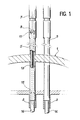
- FIG. 1 shows the upper part of the tank 1 of a pressurized water type nuclear reactor.
- the heart (not shown) made up of assemblies juxtaposed fuels.
- a structure 3 through which the vertically moving control bars are intended to be introduced more or less deeply into the heart.
- Each control bar (not shown) is connected, at its upper part, to a translation control device disposed inside a sealed enclosure 5 secured to the tank 1.
- the control device comprises a motor, not shown , located at the upper part of the enclosure 5.
- This engine drives the drive member 9 of a coupling device according to the invention by means of a shaft 7 shown in dotted lines in FIG. 1.
- the driving torque is transmitted from the driving member to the receiving member 11, then from the latter to a screw 13.
- This screw can therefore be rotated in both directions. It controls the upward and downward translation of a nut. 15 immobilized in rotation.
- the control bars are themselves integral with a bar 16 fixed to the nut 15.
- the coupling device of the invention 9, 11 shown diagrammatically in FIG. 1, must fulfill several functions. It must allow the descent and ascent of the control rods during normal reactor operation. It must also allow, as explained above, the drop of the control rods in the reactor core to allow its emergency stop. Finally, the control bars being introduced into the heart, the device must ensure their blocking in this position when the forces exerted on them tend to eject them.
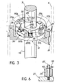
- the coupling device of the invention shown in more detail in Figures 2 to 5 provides all of these functions.
- FIG 2 there is shown in broken lines The walls 5 of the sealed enclosure which contains the control mechanism of a control bar. It is made in two parts connected by fixing flanges assembled by clamping screws 17. A seal 19 is provided between the two flanges.
- the ratchet crown 21 is arranged in the internal bore of the lower part of the enclosure 5. It is retained in this bore by a shoulder 22. A bearing 23 mounted in this crown ensures the rotation guide of the control screw of the screw-nut mechanism 13, 15. Above the ratchet ring 21 is a flange 25 which includes a guide bearing 27 for the shaft 7 which rotates the driving member 29.
- the ratchet crown 21 comprises ratchets 21a formed on the internal bore of the crown.
- the drive ring 29, arranged at the end of the shaft 7, comprises several fingers 29a, for example three in the embodiment shown in Figure 3. These fingers are arranged substantially radially. They have a first face directed radially and a second face inclined with respect to a radial direction.
- the crown 29 also includes cam profiles 29b in a number equal to that of the fingers 29a.
- the pawl ring 31 has stops 31a and 31b on its upper face. In the exemplary embodiment shown, there are three pairs of stops.
- the stops 31a have a prismatic shape while the stops 31b are presented as pawns of circular section. A depression corresponding to the shape of the section of the stops 31b can be practiced in the fingers 29a in order to distribute the pressure of the stop on the finger when a force is exerted.
- the fingers 29a are equal in number to the number of pairs of stops 31a, 31b, and are arranged between the two stops of a pair.
- Each finger has a cylindrical orifice, and each prismatic stop 31a has an identical orifice which faces it to accommodate a spring 33 therein called an arming spring. which has the function of removing the finger 29a from the stop 31a.
- the crown 31 also carries cLiquets 35.
- pawls There are as many pawls as fingers 29a, that is to say three in the example shown.
- the pawls 35 are located between the pairs of stops 31a, 31b, substantially at mid-distance, but this is not compulsory.
- the pawls 35 are pivotally mounted on the crown 31 by a pin 37.
- the axis 37 includes a stop means such as a circlip 45.
- Each pawl has a front part or stop surface 35a, capable of engaging with the ratchets 21a of the ratchet wheel 21, and a heel 35b.
- the front part 35a and the heel 35b are located on either side of the axis 37.
- Each pawl 35 pivots between a first position in LaqueLLe
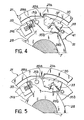
- the front or stop surface 35a is engaged in a ratchet 21a of the crown at ratchets 21 (position shown in Figure 4) and a position released in LaqueLLe this stop surface 35a is released from the ratchets 21a of the ratchet crown 21. This last position is shown in Figure 5.
- an additional ring 43 is shown, shown in dashed lines in FIG. 2, and which has the function of retaining the pawls 35.
- This ring is arranged in a plane parallel to that of the pawl ring 31 and is made integral with the latter by means of fixings fitted on the stops 31a and 31b of the pawl ring gear.
- the operation of the device is as follows.
- the engine torque is transmitted by the shaft 7 and by the drive ring 29.
- This torque is transmitted in the two directions of rotation.
- the device In its rest position, that is to say in the absence of transmitted torque, the device is in the initial position shown in FIG. 3.
- the arming springs 33 hold the fingers 29a of the stops 31a in support against cylindrical stops 31b.
- the cam profiles 29b of the drive ring 29 do not support the ta lons pawls. The latter are therefore in the engaged position, that is to say in the position for LaqueLLe
- the stop surface 35a is in contact with the ratchets 21a of the crown 21 (position shown in Figures 3 and 4).
- the receiving member drives the driving member, that is to say in the example described, the screw 13, by means of the pawl ring 31, exerts a driving torque, while that the shaft 7, integral with the drive ring 29, exerts a resistant torque or is uncoupled.
- the screw-nut system 13-15 being reversible, this force results in a torque exerted on the screw 13 and therefore on the drive crown 31.
- this torque is exerted in the trigonometric direction observed from a top view, as on the FIGS. 4 and 5.
- the pawls 35 are normally engaged in the ratchets of the crown 21.
- the rotation of this ring is therefore prohibited since the ring 21 is fixed and immobilized in rotation relative to the sealed enclosure 5.
- the torque is therefore not transmitted to the drive ring nor, consequently, to the shaft. 7.
- the ejection of the control bar from the reactor core is thus prevented.
- the coupling device of the invention can also ensure the protection of a motor element against excessive torque.
- the ratchet crown 21 is linked in rotation to the motor shaft.
- the engine torque is therefore transmitted via the pawl ring 31, in the clockwise direction of rotation, to the pawls 35.
- the force exerted on the pawls 35 is itself transmitted to the pawl ring by L 'Intermediate pawl axes 37.
- a relative rotational movement of the pawl ring relative to the drive ring occurs. This relative movement tends to bring the drive fingers 29a closer to the stops 31a and simultaneously to press the cam profiles 29b on the pawl heels 35b.
- the arming springs 33 provided between the stops 31a and each of the fingers 29a oppose this relative movement by exerting a couple of opposite directions tending to spread each stop 31a of the fingers 29a.
- the rigidity of the springs 33 can be chosen so as to transmit a torque of desired size. When the magnitude of the transmitted torque remains less than the selected limit value, the relative movement of the drive ring relative to the pawl ring is sufficiently limited so that these pawls remain in the engaged position and that the torque is transmitted.
- the arming springs 33 compress more, so that the movement relative of the drive ring relative to the pawl ring continues until the engagement of the cam profiles 29b under the heels 35b of the pawls.
- This pro- vaque The release of the stop surfaces 35a of the pawls, of the ratchets 21a and therefore the disengagement of the ratchet crown.
- the torque transmitted by the drive unit therefore remains permanently limited to the chosen limit value.
- the coupling device of the invention also applies to the transmission of a torque from a driving member to two receiving members.
- the drive member is linked in rotation to the drive ring 29.
- a first receiver is constituted by the ratchet ring 21 and a second receiver by the ratchet ring 31.
- the drive ring 29 When the driving element rotates clockwise, the drive ring 29 only drives the pawl ring 31 by means of the cylindrical stops 31b. The pawls operate by exhaust. The engine torque is therefore not transmitted to the ratchet crown.
- the drive ring 29 drives the pawl ring 31 by means of the stops 31a, the engine torque being transmitted from the drive fingers 29a to the stops 31a via the arming springs 33, as explained above.
- the rigidity of these springs is determined so as to limit the transmitted torque.
- the second receiving member constituted by the ratchet ring 21, is driven in rotation by means of the pawls 35 engaged in the ratchets 21a.
- the continuation of the relative movement of rotation of the drive ring with respect to the pawl ring causes, by compressing the arming springs, the engagement of the cam profiles 29b under the heels 35b of the pawls and, consequently, brings the latter into the released position.
- the second receiving member is therefore disengaged. It can therefore be seen that in this application, one of the receiving members, namely the pawl ring, has priority. In the direction of clockwise rotation, this priority receiving member is only driven. In the direction of trigonometric rotation, it is always driven, the second receiving member, namely the ratchet wheel, being driven only for a torque lower than a determined limit value.
Landscapes
- Physics & Mathematics (AREA)
- Engineering & Computer Science (AREA)
- Chemical & Material Sciences (AREA)
- Chemical Kinetics & Catalysis (AREA)
- Plasma & Fusion (AREA)
- General Engineering & Computer Science (AREA)
- High Energy & Nuclear Physics (AREA)
- Transmission Devices (AREA)
- Treatment Of Water By Oxidation Or Reduction (AREA)
- Analysing Materials By The Use Of Radiation (AREA)
Applications Claiming Priority (2)
| Application Number | Priority Date | Filing Date | Title |
|---|---|---|---|
| FR8406691 | 1984-04-27 | ||
| FR8406691A FR2563593B1 (fr) | 1984-04-27 | 1984-04-27 | Dispositif d'accouplement entre un organe moteur et un organe recepteur |
Publications (2)
| Publication Number | Publication Date |
|---|---|
| EP0161976A1 true EP0161976A1 (de) | 1985-11-21 |
| EP0161976B1 EP0161976B1 (de) | 1988-12-07 |
Family
ID=9303573
Family Applications (1)
| Application Number | Title | Priority Date | Filing Date |
|---|---|---|---|
| EP85400789A Expired EP0161976B1 (de) | 1984-04-27 | 1985-04-22 | Kupplungsanordnung zwischen einem Motorteil und einem Rezeptorteil |
Country Status (6)
| Country | Link |
|---|---|
| US (1) | US4661307A (de) |
| EP (1) | EP0161976B1 (de) |
| JP (1) | JPS60237393A (de) |
| CA (1) | CA1229431A (de) |
| DE (1) | DE3566751D1 (de) |
| FR (1) | FR2563593B1 (de) |
Cited By (3)
| Publication number | Priority date | Publication date | Assignee | Title |
|---|---|---|---|---|
| EP0305719A3 (de) * | 1987-08-31 | 1989-10-11 | General Electric Company | Zentrifugalbremse für Regelstabantrieb |
| EP0465271A1 (de) * | 1990-07-06 | 1992-01-08 | General Electric Company | Drehschloss, z.B. für einen Regelstabantrieb |
| EP0469828A1 (de) * | 1990-07-30 | 1992-02-05 | General Electric Company | Bremsausrüstung für Regelstabantrieb |
Families Citing this family (4)
| Publication number | Priority date | Publication date | Assignee | Title |
|---|---|---|---|---|
| US5102613A (en) * | 1990-12-06 | 1992-04-07 | General Electric Company | Radial brake assembly for a control rod drive |
| US5089211A (en) * | 1991-02-11 | 1992-02-18 | General Electric Company | Control rod drive |
| US5076994A (en) * | 1991-03-04 | 1991-12-31 | General Electric Company | Lock assembly for a control rod drive |
| US5085823A (en) * | 1991-03-05 | 1992-02-04 | General Electric Company | Latch assembly for a control rod drive |
Citations (3)
| Publication number | Priority date | Publication date | Assignee | Title |
|---|---|---|---|---|
| DE2608304A1 (de) * | 1976-02-28 | 1977-09-01 | Joachim Helff | Automatische ueberlast-schaltkupplung |
| GB2029078A (en) * | 1978-07-27 | 1980-03-12 | Commissariat Energie Atomique | Actuating device for a nuclear reactor control rod |
| EP0093055A1 (de) * | 1982-04-26 | 1983-11-02 | Commissariat à l'Energie Atomique | Auskuppelbare Katapultierverhütungseinrichtung für den Regelstabantrieb eines Kernreaktors |
Family Cites Families (3)
| Publication number | Priority date | Publication date | Assignee | Title |
|---|---|---|---|---|
| CA708093A (en) * | 1965-04-20 | Ericsson Stig | Grab means for fuel elements or the like in nuclear reactors | |
| US3924427A (en) * | 1973-07-27 | 1975-12-09 | Juaquin Jaime E San | Anti-theft automobile door lock |
| FR2495813A1 (fr) * | 1980-12-10 | 1982-06-11 | Commissariat Energie Atomique | Dispositif de commande de barres de controle par un systeme de pilotage de reacteur nucleaire |
-
1984
- 1984-04-27 FR FR8406691A patent/FR2563593B1/fr not_active Expired
-
1985
- 1985-04-22 DE DE8585400789T patent/DE3566751D1/de not_active Expired
- 1985-04-22 EP EP85400789A patent/EP0161976B1/de not_active Expired
- 1985-04-23 CA CA000479842A patent/CA1229431A/en not_active Expired
- 1985-04-26 JP JP60089119A patent/JPS60237393A/ja active Pending
- 1985-04-26 US US06/727,744 patent/US4661307A/en not_active Expired - Fee Related
Patent Citations (3)
| Publication number | Priority date | Publication date | Assignee | Title |
|---|---|---|---|---|
| DE2608304A1 (de) * | 1976-02-28 | 1977-09-01 | Joachim Helff | Automatische ueberlast-schaltkupplung |
| GB2029078A (en) * | 1978-07-27 | 1980-03-12 | Commissariat Energie Atomique | Actuating device for a nuclear reactor control rod |
| EP0093055A1 (de) * | 1982-04-26 | 1983-11-02 | Commissariat à l'Energie Atomique | Auskuppelbare Katapultierverhütungseinrichtung für den Regelstabantrieb eines Kernreaktors |
Cited By (3)
| Publication number | Priority date | Publication date | Assignee | Title |
|---|---|---|---|---|
| EP0305719A3 (de) * | 1987-08-31 | 1989-10-11 | General Electric Company | Zentrifugalbremse für Regelstabantrieb |
| EP0465271A1 (de) * | 1990-07-06 | 1992-01-08 | General Electric Company | Drehschloss, z.B. für einen Regelstabantrieb |
| EP0469828A1 (de) * | 1990-07-30 | 1992-02-05 | General Electric Company | Bremsausrüstung für Regelstabantrieb |
Also Published As
| Publication number | Publication date |
|---|---|
| FR2563593B1 (fr) | 1986-07-04 |
| DE3566751D1 (en) | 1989-01-12 |
| US4661307A (en) | 1987-04-28 |
| EP0161976B1 (de) | 1988-12-07 |
| JPS60237393A (ja) | 1985-11-26 |
| FR2563593A1 (fr) | 1985-10-31 |
| CA1229431A (en) | 1987-11-17 |
Similar Documents
| Publication | Publication Date | Title |
|---|---|---|
| FR3060630B1 (fr) | Commande d'ouverture affleurante a ejection et retraction mecanique ou electrique. | |
| EP2754466A1 (de) | Sicherheitssystem zur Fallsicherung mit Blockierfunktion am Seil | |
| EP0790385A1 (de) | Rolladenbetätigungsvorrichtung | |
| EP0951123A1 (de) | Trennbarer Schalter mit einen Schalthebel zum Öffnen und Schliessen der Phasen | |
| FR2753169A1 (fr) | Bloqueur de cordage a faible effort d'ouverture | |
| EP0161976B1 (de) | Kupplungsanordnung zwischen einem Motorteil und einem Rezeptorteil | |
| EP2485944B1 (de) | Flugzeugdrosselsteuerung mit einrastender rollenkupplung | |
| EP3715565A1 (de) | Öffnungskontrolle mit mechanischer aufstellung | |
| EP1230518A1 (de) | Feuerzeug mit einer sicherheitsvorichtung | |
| EP0084988A1 (de) | Endstück für ein Kernreaktorbrennelement mit einem federbelasteten steifen Hebel | |
| EP0389650A1 (de) | Verfahren und Katalysator zur Dehydrohalogenierung von halogenierten Kohlenwasserstoffen oder Alkylenhalogenhydrinen | |
| FR2691939A1 (fr) | Ensemble de colonne de direction, notamment pour véhicule automobile. | |
| EP0089879B1 (de) | Schnellsperrender und -entsperrender geräuscharmer Sicherheitsgurtaufroller | |
| WO2020020656A1 (fr) | Poignée d'ouvrant de véhicule automobile munie d'un système de sécurité inertiel | |
| EP0805285A2 (de) | Vorrichtung zur Kupplung zwei Wellen miteinander | |
| EP0093055B1 (de) | Auskuppelbare Katapultierverhütungseinrichtung für den Regelstabantrieb eines Kernreaktors | |
| CH636050A5 (fr) | Machine a ecrire. | |
| FR2686568A1 (fr) | Porte d'aeronef pressurise, permettant d'evacuer la pression residuelle interne avant son ouverture et de limiter la mise en pression tant qu'elle n'est pas completement fermee. | |
| EP1605123B1 (de) | Öffnungs- und Schliessmechanismus für Kraftfahrzeugtür | |
| EP0631912B1 (de) | Lenkradschloss für Kraftfahrzeuge | |
| EP0360651B1 (de) | Sicherheitseinrichtung für eine Verschubbetätigung eines Kernbrennelement-Förderwagens | |
| EP1783394B1 (de) | Sicherheitsvorrichtung für ein mechanisches Getriebe mittels einer Blockierverzahnung | |
| EP3376309B1 (de) | Aufziehmechanismus einer uhr | |
| FR2495813A1 (fr) | Dispositif de commande de barres de controle par un systeme de pilotage de reacteur nucleaire | |
| EP0947661B1 (de) | Einwegarretiereinrichtung für Rolladen |
Legal Events
| Date | Code | Title | Description |
|---|---|---|---|
| PUAI | Public reference made under article 153(3) epc to a published international application that has entered the european phase |
Free format text: ORIGINAL CODE: 0009012 |
|
| AK | Designated contracting states |
Designated state(s): BE DE GB IT |
|
| 17P | Request for examination filed |
Effective date: 19860416 |
|
| 17Q | First examination report despatched |
Effective date: 19870727 |
|
| RAP1 | Party data changed (applicant data changed or rights of an application transferred) |
Owner name: COMMISSARIAT A L'ENERGIE ATOMIQUE |
|
| GRAA | (expected) grant |
Free format text: ORIGINAL CODE: 0009210 |
|
| AK | Designated contracting states |
Kind code of ref document: B1 Designated state(s): BE DE GB IT |
|
| ITF | It: translation for a ep patent filed | ||
| REF | Corresponds to: |
Ref document number: 3566751 Country of ref document: DE Date of ref document: 19890112 |
|
| GBT | Gb: translation of ep patent filed (gb section 77(6)(a)/1977) | ||
| PLBE | No opposition filed within time limit |
Free format text: ORIGINAL CODE: 0009261 |
|
| STAA | Information on the status of an ep patent application or granted ep patent |
Free format text: STATUS: NO OPPOSITION FILED WITHIN TIME LIMIT |
|
| 26N | No opposition filed | ||
| PGFP | Annual fee paid to national office [announced via postgrant information from national office to epo] |
Ref country code: DE Payment date: 19910325 Year of fee payment: 7 |
|
| PGFP | Annual fee paid to national office [announced via postgrant information from national office to epo] |
Ref country code: BE Payment date: 19910409 Year of fee payment: 7 |
|
| PGFP | Annual fee paid to national office [announced via postgrant information from national office to epo] |
Ref country code: GB Payment date: 19910417 Year of fee payment: 7 |
|
| ITTA | It: last paid annual fee | ||
| PG25 | Lapsed in a contracting state [announced via postgrant information from national office to epo] |
Ref country code: GB Effective date: 19920422 |
|
| PG25 | Lapsed in a contracting state [announced via postgrant information from national office to epo] |
Ref country code: BE Effective date: 19920430 |
|
| BERE | Be: lapsed |
Owner name: COMMISSARIAT A L'ENERGIE ATOMIQUE Effective date: 19920430 |
|
| GBPC | Gb: european patent ceased through non-payment of renewal fee | ||
| PG25 | Lapsed in a contracting state [announced via postgrant information from national office to epo] |
Ref country code: DE Effective date: 19930101 |