EP0161995B1 - Verfahren zur Behandlung von Giessereisänden zum Wiedererlangen von Chromit und Vorrichtung dazu - Google Patents
Verfahren zur Behandlung von Giessereisänden zum Wiedererlangen von Chromit und Vorrichtung dazu Download PDFInfo
- Publication number
- EP0161995B1 EP0161995B1 EP85420051A EP85420051A EP0161995B1 EP 0161995 B1 EP0161995 B1 EP 0161995B1 EP 85420051 A EP85420051 A EP 85420051A EP 85420051 A EP85420051 A EP 85420051A EP 0161995 B1 EP0161995 B1 EP 0161995B1
- Authority
- EP
- European Patent Office
- Prior art keywords
- mixture
- plate
- chromite
- silica
- installation
- Prior art date
- Legal status (The legal status is an assumption and is not a legal conclusion. Google has not performed a legal analysis and makes no representation as to the accuracy of the status listed.)
- Expired - Lifetime
Links
Images

Classifications
-
- B—PERFORMING OPERATIONS; TRANSPORTING
- B22—CASTING; POWDER METALLURGY
- B22C—FOUNDRY MOULDING
- B22C5/00—Machines or devices specially designed for dressing or handling the mould material so far as specially adapted for that purpose
-
- B—PERFORMING OPERATIONS; TRANSPORTING
- B03—SEPARATION OF SOLID MATERIALS USING LIQUIDS OR USING PNEUMATIC TABLES OR JIGS; MAGNETIC OR ELECTROSTATIC SEPARATION OF SOLID MATERIALS FROM SOLID MATERIALS OR FLUIDS; SEPARATION BY HIGH-VOLTAGE ELECTRIC FIELDS
- B03B—SEPARATING SOLID MATERIALS USING LIQUIDS OR USING PNEUMATIC TABLES OR JIGS
- B03B4/00—Separating by pneumatic tables or by pneumatic jigs
- B03B4/02—Separating by pneumatic tables or by pneumatic jigs using swinging or shaking tables
-
- B—PERFORMING OPERATIONS; TRANSPORTING
- B22—CASTING; POWDER METALLURGY
- B22C—FOUNDRY MOULDING
- B22C5/00—Machines or devices specially designed for dressing or handling the mould material so far as specially adapted for that purpose
- B22C5/18—Plants for preparing mould materials
-
- Y—GENERAL TAGGING OF NEW TECHNOLOGICAL DEVELOPMENTS; GENERAL TAGGING OF CROSS-SECTIONAL TECHNOLOGIES SPANNING OVER SEVERAL SECTIONS OF THE IPC; TECHNICAL SUBJECTS COVERED BY FORMER USPC CROSS-REFERENCE ART COLLECTIONS [XRACs] AND DIGESTS
- Y10—TECHNICAL SUBJECTS COVERED BY FORMER USPC
- Y10S—TECHNICAL SUBJECTS COVERED BY FORMER USPC CROSS-REFERENCE ART COLLECTIONS [XRACs] AND DIGESTS
- Y10S241/00—Solid material comminution or disintegration
- Y10S241/10—Foundry sand treatment
Definitions
- the subject of the invention relates, in particular to the technical sectors of foundry, the manufacture of parts by casting of metal in molds, the recovery of materials or components of the molds and in particular chromite and silica, and also of the separation in general of the components of a mixture which have different densities.
- the object of the process for treating foundry sands according to the invention is to separate and recover, after casting, the silica, the chromite and the metallic shot, so as to be able to reuse the sand and the chromite which can be thus implement in repetitive cycles subject to replacing the losses due to various causes.
- the mixture is passed from the intermediate container to a size grading device with sieves making it possible to separate grains or particles in several batches of different particle sizes, each batch is conveyed to a special separating table, the mixture is subjected to combined and simultaneous effects according to which, on the one hand, the components are fluidized by the effect air or a gaseous fluid under pressure through a plate or support ensuring microsuperficial diffusion, while, on the other hand, vibrations of amplitude, frequency, intensity and adjustable directional effect combined with at least one mass adjustable in intensity and position relative to the plate or support, so as to subject said plate or support for a tilting effect tending to raise the lower part of the tray which is mounted on an assembly, so as to give the tray a spatial freedom in any direction to obtain at any point of the tray or support, an
- the installation comprises, in known manner, a general storage silo into which the mixture is sent which is then conveyed to an intermediate silo by means of a pneumatic blower.
- a regulating valve controls the flow rate of the mixture to be sorted which then passes by gravity, on a particle size sorter shaped to separate the grains or particles of the mixture in several batches of different particle sizes and densities, each of these batches being conveyed to a separating table shaped to separate the chromite from the silica of each batch by means of a tray inclined shaped to ensure micro-surface diffusion, one of the transverse ends of the plate on the lowest side being slaved to a vibrating device, while the other opposite end of said plate is slaved to a set of masses, the plate being mounted inclined by being subject to elastically deformable support elements; drainage channel containers or conveyor belts are shaped to collect in a common way, for the separating tables, on the one hand, the silica, and, on the other hand, the chromite.
- the process for treating foundry sands can result from shot peening.
- the mixture resulting from shot peening is recovered, this mixture being stored; the mixture is conveyed from the storage location to an intermediate container; the mixture is passed from the intermediate container through a sorting device shaped to separate the particles or metal grains which are recovered and which are evacuated; the mixture free of particles and metallic grains is passed from said sorting device to a fluidized bed sorting device making it possible to separate grains or particles into several categories of different densities; concerning these categories, taken in order of increasing densities, fines and dust are collected in a general dust collector; the pure silica is collected and evacuated to an intermediate container of a facility for treating the sand for stall, the category consisting of a mixture of silica and chromite; the pure chromite is collected.
- the installation for implementing the method comprises a storage silo which receives the mixture resulting from shot peening and from which said mixture is conveyed in an intermediate silo, using a blower pneumatic; the flow rate of the mixture to be sorted is controlled by a central regulating valve to pass by gravity effect, from the silo to a magnetic sorter with drum which eliminates the magnetic particles contained in the mixture, said particles being removed by means of a conveyor belt; the mixture without particles or metallic grains being directed to a fluidized bed sorting device.
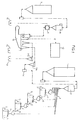
- FIG. 1 shows in a purely schematic manner and in parallel, the installation corresponding to the process for treating the mixture resulting from the release and the installation corresponding to the process for treating the mixture resulting from shot peening, it being specified that if each of the installations can be assembled and used separately, provision is made for their use in a single overall installation with useful links and transfers between the two installations.
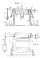
- FIG. 2 illustrates by a schematic overview, the separating table with an inclined plate which implements the method of separation of the components of different densities of a mixture.
- Figures 3, 4 and 5 are corresponding views, respectively in elevation, side and plan, which show an embodiment of the separating table.
- these separating tables (4) could be produced in any way and according to any known method, for example using grids or screens having suitably calibrated openings, or else according to the characteristic arrangements which have been the subject of French Patents N ° 73.29274, 74.28510, 78.20580.
- FIG. 1 also illustrates this installation in a schematic manner, and we see the storage silo (7) which receives the mixture resulting from shot peening and from which said mixture is conveyed to an intermediate silo (8) by any known means and using for example a pneumatic blower.
- the flow rate of the mixture to be sorted is controlled by a regulating valve to pass by gravity effect, from the silo (8) to a magnetic drum sorter (9) of the type known per se, which eliminates the magnetic particles contained in the mixture, particles which are removed for example by means of a conveyor belt (10).
- the mixture without particles or metallic grains is then directed to a sorter device (11) with a fluidized bed.
- a process is used for preparing the components (chromite and silica) which have different densities.
- the mixture is subjected to combined and simultaneous effects according to which, on the one hand, the components are fluidized by the effect of air or a gaseous fluid under pressure through an inclined plane or plate ( 16) of the separating table (4), said plate being shaped to ensure, in a known manner, a microsuperficial diffusion.
- One of the transverse ends of the plate (16), on the lowest side, is controlled by a vibrating device (17), while the other end is controlled by a set of adjustable masses (18).
- the masses (18) are mounted projecting from the active part of the plate, being supported by arms (18a) mounted in the extension and beyond the lateral sides of said plate.
- the plate is likely to be subjected to vibrations of adjustable amplitude, frequency, intensity and directional effect combined with an adjustable torque effect, to ensure separate evacuation from the plate, of each component, chromite and silica, of the mixture.
- the diffuser plate (16) is mounted by any known and appropriate means, in an inclined and adjustable manner on the support frame (19) of the table (4) while being secured, at each of its high and low transverse ends, in particular to blocks or elements (20) with elastic deformation capacity.
- Under the plate (16) is formed a volume closed by a flexible membrane (22).
- An air generator (23) or other means opens into the bottom of the sealed volume (22), to send air under pressure inside said volume, to fluidize the components, chromite and silica, placed on the tray.
- FIGS. 3, 4 and 5 Illustrated in FIGS. 3, 4 and 5, an embodiment of the separating table corresponding to the operating principle shown in FIG. 2.
- the mixture is brought with a suitable flow rate on the inclined plate (16) of the porous type.
- chromite constitutes the dense products
- silica constitutes the light or less dense products.
- the vibrator devices (17) subject, in its plane, the plate (16) to adjustable frequency and amplitude vibrations. These vibrations are combined with the effects of adjustable masses (18), in intensity, and in position relative to the plate (16).
- the masses can be adjusted in height on a vertical element (18b) of support arm (18a) and / or moved in length relative to said arms.
- the set of masses (18) being linked to the upper part of the plate (16), communicates to the latter, in combination with the amplitudes of the vibrator (17), a tilting effect which tends to cause the elevation of the lower part of the tray.
- the elastic supports (20) give the tray a spatial freedom in all directions, the flexible membrane (22) ensuring air tightness between the tray (16) and the separating table support housing (4).
- the longitudinal tilting torque created by the adjustable masses is also capable of advancing heavy products in contact with the table, by ballistic phenomenon. Indeed, under a very strong acceleration following very significantly the resultant ⁇ R , the chromite grain must take off from the plate and fall back when the said plate has made its return movement and so on.
Landscapes
- Engineering & Computer Science (AREA)
- Mechanical Engineering (AREA)
- Molds, Cores, And Manufacturing Methods Thereof (AREA)
- Combined Means For Separation Of Solids (AREA)
- Mold Materials And Core Materials (AREA)
- Physical Or Chemical Processes And Apparatus (AREA)
- Processing Of Solid Wastes (AREA)
- Solid-Sorbent Or Filter-Aiding Compositions (AREA)
- Glanulating (AREA)
Claims (9)
- Behandlungsverfahren für die Giessereisande, die aus einem Abstreifen resultieren, gemäss welchem, nach der Formung der Stücke und dem Herausziehen derselben aus den gebrochenen Formen, das sich aus dem Abstreifen ergebende Gemisch in einem ersten Arbeitsvorgang rückgewonnen, eingelagert, und dann von der Lagerungsstelle (1) aus bis zu einem Zwischenbehälter (2) befördert wird, dadurch gekennzeichnet, dass das Gemisch von dem Zwischenbehälter (2) aus bis zu einem granulometrischen Siebscheider (3) zum Ausscheiden der Körnchen oder Teilchen in mehrere Haufen unterschiedlicher Korngrösse versetzt wird, wobei jeder eine der Haufen bis zu einer speziellen Ausscheidungsplatte (4) geführt wird ; dass das Gemisch sich dann unter kombinierten und gleichseitigen Wirkungen zu stehen kommt, gemäss welchen, einerseits, die Bestandteile durch die Wirkung der Druckluft oder einer druckbanspruchten, gasförmigen Flüssigkeit durch eine Tragplatte oder einen Träger (16) hindurch fluidisiert werden, die oder der eine Oberflächemikrodiffusion bewirkt, während andererseits der Tragplatte oder dem Träger Ersehütterungen verleiht werden, die in der Grösse, der Frequenz, der Stärke und der richtungsgebenden Wirkung verstellbar und mit am wenigstens einer Masse (18) kombiniert sind, die stärkenmässig und stellungsmässig bezüglich der Tragplatte oder dem Träger (16) auch verstellbar ist, damit die genannte Tragplatte oder der genannte Träger durch eine Schwenkwirkung beansprucht wird, die danach strebt, den tiefliegenden Teil der Tragplatte anzuheben, auf welcher ein Komplex angeordnet ist, damit eine Raumfreiheit der Tragplatte nach allen Richtungen zum Erreichen in beliebiger Stelle der Tragplatte oder des Trägers einer einer Wirkung zu verleihen, die eine Komponentkraft zum Auswerfen nach dem Oberteil und weiter hinaus bildet, wobei die getreente Evakuierung ausserhalb der Tragplatte oder des Trägers und weiter hinaus des Chromits und der Kieselerde vonstatten gehen kann.
- Behandlungsverfahren für die Giessereisande, die aus einer Schrottbestrahlung resultieren, gemäss welchem das aus der Schrottbestrahlung resultierende Gemisch rückgewonnen und eingelagert, und dann von der Einlagerungsstelle (7) aus bis zu einem Zwischenbehälter (8) befördert wird, dadurch gekennzeichnet, dass das Gemisch von dem Zwischenbehälter (8) aus in eine Scheidervorrichtung (9) versetzt wird, die für die Trennung der metallischen Körnchen oder Teilschen ausgestaltet ist, die rückgewonnen und evakuiert werden ; dass das von metallischen Körnchen und Teilchen befreite Gemisch von der besagten Scheidervorrichtung aus bis zu einer Scheidervorrichtung mit fluidisiertem Bett (11) versetzt wird, die die Trennung der Kôrnchen oder Teilchen in mehreren Klassen von unterschiedlichen Dichtigkeiten gestattet ; und dass die Feinteilschen und der Staub bei diesen in zunehmender Reihenfolge erfassten Dichtigkeiten in einer Hauptentstaubungsanlage gesammelt werden, wobei die reine Kieselerde aufgefangen wird, indem die aus einem Gemisch von Kieselerde und Chromit bestehende Klasse bis zu einem Zwischenbehälter eine Behandlungsanlage für den Abstreifensand abgeführt und das reine Chromit gesammelt wird.
- Anlage für das Bewerkstelligen des Verfahrens nach Anspruch 1, die einen Hauptlagerungsbunker (1) aufweist, in welchen das Gemisch befördert und danach bis zu einem Zwischenbunker (2) vermittels einer Druckluftpulsiervorrichtung geführt wird, dadurch gekennzeichnet, dass ein Regulierventil die Liefermenge des zu scheidenden Gemisches Kontrolliert, das dann durch die Wirkung der Schwere auf einen Kornungsscheider (3) versetzt wird, der zum Ausscheiden der Körnchen oder der Teilchen des Gemisches in verschiedenen Haufen unterschiedlicher Korngrösse und Dichtigkeiten ausgestaltet ist, wobei jeder einer dieser Haufen bis zu einer Trennungsplatte (4) befördert wird, die für die Trennung des Chromits und der Kieselerde Jedes Haufens vermittels eines geneigten, zum Bewirken einer oberflächlichen Mikrodiffusion ausgestalteten Tellers (16) vorgesehen ist ; dass eine der Querenden des Tellers, an der tiefstgelegenen Seite, durch eine Erschütterungsvorrichtung angesteuert wird, wahrend das andere, entgegengesetzte Ende des besagten Tellers durch einen Massenkomplex (18) angesteuert ist, wobei der Teller geneigt und unter Beanspruchung von elastisch verformbaren Trâgerelementen (22) angeordnet ist ; und dass Evakuierungskanalbehälter oder Evakuierungsförderriemen (5) und (6) für die Rückgewinnung in üblicher Weise, für die Trennungsplatten (4), einerseits der Kieselerde und andererseits des Chromits, vorgesehen sind.
- Anlage für das Bewerkstelligen des Verfahrens nach Anspruch 2, dadurch gekennzeichnet, dass sie einen Einlagerungsbunker (7) zur Aufnahme des aus der Schrottbestrahlung resultierenden Gemisches aufweist, das von diesem Bunker aus, unter Verwendung einer Druckluftpulsiervorrichtung, in einen Zwischenbunker (8) befördert wird, wobei die Liefermenge des zu scheidenden Gemisches durch ein Zentralregulierventil Kontrolliert ist, damit dieses Gemisch, unter der Wirkung der Schwere, von dem Bunker (8) nach einem magnetischen Trommelscheider (9) versetzt wird, der die in dem Gemisch befindlichen magnetischen Teilchen beseitigt ; und dass die genannten Teilchen mittels eines Förderriemens (10) evakuiert werden, wobei das von Metallkörnchen und Metallteilchen freie Gemisch bis zu einer Scheidervorrichtung (11) mit fluidisiertem Bett geführt wird.
- Anlage nach Anspruch 4, dadurch gekennzeichnet, dass die Scheidervorrichtung (11) für das Ausscheiden der durch eine Hauptentstaubungsanlage (12) gesammelten Feinteilchen und Staubteilchen, aus der durch eine Saugvorrichtung (11a) eingesaugten reinen Kieselerde ausgestaltet ist, die evakuiert wird, sowie eines aus Kieselerde und Chromit bestehenden Gemisches, das durch eine zweite Saugvorrichtung des Scheiders angesaugt wird, wobei das besagte Gemisch nach dem Abstreifensandkreislauf des reinen Chromits geführt wird, das nachher evakuiert ist.
- Anlage nach Anspruch 3, dadurch gekennzeichnet, dass ein durch eine biegsame Membrane (22) geschlossener Raum unter dem Teller (16) gebildet ist, wobei ein Luftgenerator (23) oder desgleichen in den Raumunterteil mündet, um in den Innenteil des besagten Raums Druckluft zu fördern, damit die auf dem Teller befindlichen Bestandteile fluidisiert werden.
- Anlage nach Anspruch 3, dadurch gekennzeichnet, dass die Massen aus dem wirksamen Teil des Tellers (16) nach der obersten Seite hinausragend montiert werden, und durch Arme (18a) getragen sind, die in der Verlängerung und jenseits der seitlichen Teile des Tellers (16) angeordnet sind.
- Anlage nach Anspruch 7, dadurch gekennzeichnet, dass die Massen (18) höhenverstellbar und längs eines Vertikalelements (18b) verschiebbar sind, das am Ende jedes Trägerarms angeordnet ist.
- Anlage nach Anspruch 3, dadurch gekennzeichnet, dass die Querenden des Diffusionstellers (16) für die Evakuierung der ausgechiedenen Bestandteile sowie für die Rückgewwing derselben in geeigneten Mitteln ausgesaltet sind.
Applications Claiming Priority (2)
| Application Number | Priority Date | Filing Date | Title |
|---|---|---|---|
| FR8404696A FR2561554B1 (fr) | 1984-03-21 | 1984-03-21 | Procede de traitement des sables de fonderie pour, notamment, recuperer la chromite, ainsi que l'installation et les moyens de mise en oeuvre du procede |
| FR8404696 | 1984-03-21 |
Publications (2)
| Publication Number | Publication Date |
|---|---|
| EP0161995A1 EP0161995A1 (de) | 1985-11-21 |
| EP0161995B1 true EP0161995B1 (de) | 1991-06-12 |
Family
ID=9302473
Family Applications (1)
| Application Number | Title | Priority Date | Filing Date |
|---|---|---|---|
| EP85420051A Expired - Lifetime EP0161995B1 (de) | 1984-03-21 | 1985-03-19 | Verfahren zur Behandlung von Giessereisänden zum Wiedererlangen von Chromit und Vorrichtung dazu |
Country Status (10)
| Country | Link |
|---|---|
| US (1) | US4671867A (de) |
| EP (1) | EP0161995B1 (de) |
| KR (1) | KR850007011A (de) |
| AT (1) | ATE64332T1 (de) |
| DE (2) | DE3583184D1 (de) |
| ES (2) | ES8801592A1 (de) |
| FR (1) | FR2561554B1 (de) |
| IL (1) | IL74588A (de) |
| RO (1) | RO93730B (de) |
| YU (1) | YU45085A (de) |
Families Citing this family (13)
| Publication number | Priority date | Publication date | Assignee | Title |
|---|---|---|---|---|
| DE3719288A1 (de) * | 1987-06-10 | 1988-12-22 | Foerder & Anlagentechnik Gmbh | Verfahren und anordnung zum trennen von schuettguetern unterschiedlichen spezifischen gewichtes |
| US5071541A (en) * | 1988-09-30 | 1991-12-10 | The Boeing Company | Method and apparatus for sorting a mixture of particles |
| US4943368A (en) * | 1988-11-15 | 1990-07-24 | Pittsburgh Mineral & Environmental Technology, Inc. | Nonmetallic abrasive blasting material recovery process including an electrostatic separation step |
| DE4109452A1 (de) * | 1991-03-22 | 1992-09-24 | Klein Alb Gmbh Co Kg | Verfahren und vorrichtung zum sichten von sand o. dgl. rieselgut |
| CH689202A5 (de) * | 1993-12-10 | 1998-12-15 | Fischer Georg Giessereianlagen | Verfahren zum Regenerieren von Giesserei-Altsand mit Anteilen von schwach magnetischen Stoffen. |
| US6277128B1 (en) | 1998-07-11 | 2001-08-21 | J. Scott Muldner | Skin abrasion treatment device |
| US6631808B2 (en) | 2001-08-07 | 2003-10-14 | Particle And Coating Technologies, Inc. | Air classifier system for the separation of particles |
| US6691765B2 (en) | 2001-08-07 | 2004-02-17 | Noram Technology, Ltd. | Products for the manufacture of molds and cores used in metal casting and a method for their manufacture and recycle from crushed rock |
| KR20040009290A (ko) * | 2002-07-23 | 2004-01-31 | 아이앤아이스틸 주식회사 | 주물사의 분리시스템 |
| US8764350B2 (en) * | 2008-06-05 | 2014-07-01 | Alstom Technology Ltd | Conveyor for transporting powder, and a method for conveying powder |
| CN109641263B (zh) * | 2016-08-22 | 2021-04-06 | 艾莫考国际公司 | 用于从铸造废料回收砂和活性粘土的工艺过程 |
| CN106424542A (zh) * | 2016-08-29 | 2017-02-22 | 山西永益铸管股份有限公司 | 铸管废砂回收装置 |
| DE102020004891A1 (de) * | 2020-08-11 | 2022-02-17 | Allgaier Werke Gmbh | System und Verfahren zur gravimetrischen Sortierung eines Stoffgemischs |
Family Cites Families (16)
| Publication number | Priority date | Publication date | Assignee | Title |
|---|---|---|---|---|
| FR763365A (fr) * | 1933-01-21 | 1934-04-30 | Manche Atel Chantiers | Procédé et appareil pour la séparation à sec de produits de densités différentes |
| US2348344A (en) * | 1941-11-25 | 1944-05-09 | Birtley Co Ltd | Process of separating intermixed divided materials |
| US2452362A (en) * | 1944-12-19 | 1948-10-26 | Link Belt Co | Apparatus for treating flowable solids |
| US2635753A (en) * | 1948-06-01 | 1953-04-21 | Lyle G Mclean | Air stratifier |
| US2698086A (en) * | 1952-01-10 | 1954-12-28 | Vogel Walter | Arrangement for removing dust from granular material |
| FR1477593A (fr) * | 1966-03-02 | 1967-04-21 | Siderurgie Fse Inst Rech | Procédé de classement pneumatique d'un produit pulvérulent |
| US3764078A (en) * | 1970-12-01 | 1973-10-09 | Applic Prod Ind | Apparatus for regenerating foundry sand |
| DE2252259A1 (de) * | 1972-10-25 | 1974-05-09 | Halbergerhuette Gmbh | Einrichtung zum rueckgewinnen von giesserei-formgrundstoff |
| DE2448333A1 (de) * | 1974-10-10 | 1976-04-22 | Escher Wyss Gmbh | Formsandreiniger |
| US4144088A (en) * | 1977-01-19 | 1979-03-13 | Kenzler Engineering Company, Inc. | Process of reclaiming used foundry sand |
| FR2425279A1 (fr) * | 1978-05-11 | 1979-12-07 | Sosson Guy | Procede et dispositif pour trier et classer des particules solides de matieres diverses de densites relativement voisines |
| US4354641A (en) * | 1979-02-26 | 1982-10-19 | Weatherly Foundry & Manufacturing Co. | Apparatus for removing no-bake coatings from foundry sand and classifying the reclaimed sand |
| US4449566A (en) * | 1979-04-09 | 1984-05-22 | Ford Motor Company | Foundry sand reclamation |
| SU933178A1 (ru) * | 1980-10-09 | 1982-06-07 | Научно-Исследовательский И Проектно-Конструкторский Институт Стройматериалов Им.Дадашева | Способ регенерации отработанных формовочных песчано-глинистых смесей |
| JPS5897462A (ja) * | 1981-12-07 | 1983-06-09 | Mazda Motor Corp | 鋳型バツクアツプ用シヨツトの分離回収装置 |
| JPH109542A (ja) * | 1996-06-24 | 1998-01-16 | Babcock Hitachi Kk | ごみ焼却方法 |
-
1984
- 1984-03-21 FR FR8404696A patent/FR2561554B1/fr not_active Expired
-
1985
- 1985-03-13 IL IL74588A patent/IL74588A/xx unknown
- 1985-03-19 DE DE8585420051T patent/DE3583184D1/de not_active Expired - Lifetime
- 1985-03-19 AT AT85420051T patent/ATE64332T1/de not_active IP Right Cessation
- 1985-03-19 EP EP85420051A patent/EP0161995B1/de not_active Expired - Lifetime
- 1985-03-19 RO RO118056A patent/RO93730B/ro unknown
- 1985-03-19 DE DE198585420051T patent/DE161995T1/de active Pending
- 1985-03-20 YU YU00450/85A patent/YU45085A/xx unknown
- 1985-03-20 KR KR1019850001813A patent/KR850007011A/ko not_active Abandoned
- 1985-03-21 US US06/714,496 patent/US4671867A/en not_active Expired - Fee Related
- 1985-03-21 ES ES541470A patent/ES8801592A1/es not_active Expired
-
1987
- 1987-10-08 ES ES557767A patent/ES8900269A1/es not_active Expired
Also Published As
| Publication number | Publication date |
|---|---|
| ES541470A0 (es) | 1988-02-16 |
| YU45085A (en) | 1988-10-31 |
| ES557767A0 (es) | 1988-10-01 |
| FR2561554B1 (fr) | 1986-08-14 |
| KR850007011A (ko) | 1985-10-30 |
| ES8900269A1 (es) | 1988-10-01 |
| US4671867A (en) | 1987-06-09 |
| IL74588A (en) | 1987-10-20 |
| ES8801592A1 (es) | 1988-02-16 |
| DE3583184D1 (de) | 1991-07-18 |
| EP0161995A1 (de) | 1985-11-21 |
| RO93730A (ro) | 1988-06-30 |
| FR2561554A1 (fr) | 1985-09-27 |
| DE161995T1 (de) | 1987-03-19 |
| RO93730B (ro) | 1988-07-02 |
| ATE64332T1 (de) | 1991-06-15 |
| IL74588A0 (en) | 1985-06-30 |
Similar Documents
| Publication | Publication Date | Title |
|---|---|---|
| EP0161995A1 (de) | Verfahren zur Behandlung von Giessereisänden zum Wiedererlangen von Chromit und Vorrichtung dazu | |
| US3934374A (en) | Sand reclamation system | |
| JP6462144B2 (ja) | 顆粒ポリシリコンの分級および除塵のための装置および方法 | |
| US3863847A (en) | Foundry sand reducer and reclaimer | |
| JPH04504078A (ja) | 主に建築現場廃棄物からの有価物質の回収の方法及び装置 | |
| CN107377384B (zh) | 一种用于农业的选种设备及其方法 | |
| US3084876A (en) | Vibratory grinding | |
| JP2877836B2 (ja) | 材料分級装置 | |
| JPS6113894B2 (de) | ||
| JP2000083998A (ja) | 砂粒状の材料を素材的に分離するための方法および装置 | |
| EA014392B1 (ru) | Ленточное фильтровальное устройство | |
| US4319995A (en) | Process and apparatus for separating particles by relative density | |
| US4299692A (en) | Apparatus for handling a mold box in a vacuum casting system | |
| US4074867A (en) | Method and apparatus for comminuting sand clods | |
| US4731959A (en) | Vibratory casting cleaning | |
| US3777887A (en) | Apparatus for separating dry granular material | |
| US5586660A (en) | Process and apparatus for screening a stream of bulk material | |
| CN114850395B (zh) | 一种覆膜砂生产回收循环系统 | |
| FR2636863A1 (fr) | Installation de separation et de nettoyage de produits broyes | |
| CN118218243A (zh) | 一种煤矿大小分选装料装置 | |
| CN209849026U (zh) | 硅铁破碎分级筛分系统 | |
| CA2053184A1 (en) | Process and device for cleaning of bulk goods | |
| US3521750A (en) | Laboratory sifter | |
| JPH0624644B2 (ja) | 固体分離装置 | |
| US2795828A (en) | Machine for knocking out foundry moulding boxes |
Legal Events
| Date | Code | Title | Description |
|---|---|---|---|
| PUAI | Public reference made under article 153(3) epc to a published international application that has entered the european phase |
Free format text: ORIGINAL CODE: 0009012 |
|
| AK | Designated contracting states |
Designated state(s): AT BE CH DE GB IT LI LU NL SE |
|
| 17P | Request for examination filed |
Effective date: 19860509 |
|
| ITCL | It: translation for ep claims filed |
Representative=s name: ING. A. GIAMBROCONO & C. S.R.L. |
|
| TCNL | Nl: translation of patent claims filed | ||
| TCAT | At: translation of patent claims filed | ||
| DET | De: translation of patent claims | ||
| 17Q | First examination report despatched |
Effective date: 19881103 |
|
| GRAA | (expected) grant |
Free format text: ORIGINAL CODE: 0009210 |
|
| AK | Designated contracting states |
Kind code of ref document: B1 Designated state(s): AT BE CH DE GB IT LI LU NL SE |
|
| PG25 | Lapsed in a contracting state [announced via postgrant information from national office to epo] |
Ref country code: SE Effective date: 19910612 Ref country code: NL Effective date: 19910612 Ref country code: AT Effective date: 19910612 |
|
| REF | Corresponds to: |
Ref document number: 64332 Country of ref document: AT Date of ref document: 19910615 Kind code of ref document: T |
|
| REF | Corresponds to: |
Ref document number: 3583184 Country of ref document: DE Date of ref document: 19910718 |
|
| GBT | Gb: translation of ep patent filed (gb section 77(6)(a)/1977) | ||
| ITF | It: translation for a ep patent filed | ||
| NLV1 | Nl: lapsed or annulled due to failure to fulfill the requirements of art. 29p and 29m of the patents act | ||
| PGFP | Annual fee paid to national office [announced via postgrant information from national office to epo] |
Ref country code: GB Payment date: 19920310 Year of fee payment: 8 |
|
| PGFP | Annual fee paid to national office [announced via postgrant information from national office to epo] |
Ref country code: CH Payment date: 19920316 Year of fee payment: 8 |
|
| PGFP | Annual fee paid to national office [announced via postgrant information from national office to epo] |
Ref country code: BE Payment date: 19920319 Year of fee payment: 8 |
|
| PG25 | Lapsed in a contracting state [announced via postgrant information from national office to epo] |
Ref country code: LU Free format text: LAPSE BECAUSE OF NON-PAYMENT OF DUE FEES Effective date: 19920331 |
|
| PLBE | No opposition filed within time limit |
Free format text: ORIGINAL CODE: 0009261 |
|
| STAA | Information on the status of an ep patent application or granted ep patent |
Free format text: STATUS: NO OPPOSITION FILED WITHIN TIME LIMIT |
|
| PGFP | Annual fee paid to national office [announced via postgrant information from national office to epo] |
Ref country code: DE Payment date: 19920512 Year of fee payment: 8 |
|
| 26N | No opposition filed | ||
| PG25 | Lapsed in a contracting state [announced via postgrant information from national office to epo] |
Ref country code: GB Effective date: 19930319 |
|
| PG25 | Lapsed in a contracting state [announced via postgrant information from national office to epo] |
Ref country code: LI Effective date: 19930331 Ref country code: CH Effective date: 19930331 Ref country code: BE Effective date: 19930331 |
|
| BERE | Be: lapsed |
Owner name: CENTRE STEPHANOIS DE RECHERCHES MECANIQUES HYDROM Effective date: 19930331 |
|
| GBPC | Gb: european patent ceased through non-payment of renewal fee |
Effective date: 19930319 |
|
| REG | Reference to a national code |
Ref country code: CH Ref legal event code: PL |
|
| PG25 | Lapsed in a contracting state [announced via postgrant information from national office to epo] |
Ref country code: DE Effective date: 19931201 |