EP0161996B1 - Verfahren und Vorrichtung zur Echtzeitkorrelationsmessung von Verzögerungen zwischen sich statistisch entsprechenden elektrischen Signalen - Google Patents
Verfahren und Vorrichtung zur Echtzeitkorrelationsmessung von Verzögerungen zwischen sich statistisch entsprechenden elektrischen Signalen Download PDFInfo
- Publication number
- EP0161996B1 EP0161996B1 EP85420060A EP85420060A EP0161996B1 EP 0161996 B1 EP0161996 B1 EP 0161996B1 EP 85420060 A EP85420060 A EP 85420060A EP 85420060 A EP85420060 A EP 85420060A EP 0161996 B1 EP0161996 B1 EP 0161996B1
- Authority
- EP
- European Patent Office
- Prior art keywords
- delay
- samples
- signal
- peak
- correlation function
- Prior art date
- Legal status (The legal status is an assumption and is not a legal conclusion. Google has not performed a legal analysis and makes no representation as to the accuracy of the status listed.)
- Expired
Links
Images


Classifications
-
- G—PHYSICS
- G01—MEASURING; TESTING
- G01P—MEASURING LINEAR OR ANGULAR SPEED, ACCELERATION, DECELERATION, OR SHOCK; INDICATING PRESENCE, ABSENCE, OR DIRECTION, OF MOVEMENT
- G01P3/00—Measuring linear or angular speed; Measuring differences of linear or angular speeds
- G01P3/64—Devices characterised by the determination of the time taken to traverse a fixed distance
- G01P3/80—Devices characterised by the determination of the time taken to traverse a fixed distance using auto-correlation or cross-correlation detection means
- G01P3/806—Devices characterised by the determination of the time taken to traverse a fixed distance using auto-correlation or cross-correlation detection means in devices of the type to be classified in G01P3/68
-
- G—PHYSICS
- G06—COMPUTING OR CALCULATING; COUNTING
- G06F—ELECTRIC DIGITAL DATA PROCESSING
- G06F17/00—Digital computing or data processing equipment or methods, specially adapted for specific functions
- G06F17/10—Complex mathematical operations
- G06F17/15—Correlation function computation including computation of convolution operations
Definitions
- the present invention relates to the technical field of the measurement, by correlation, of delays between two statistically similar signals.
- This measurement technique is a well known method. It consists in taking two electrical signals at two points located respectively at a fixed fixed distance from a mobile medium with a non-homogeneous surface.
- One of the signals is picked up at a first point and stored in a delay channel, while the second signal is picked up at the second point and routed on a direct processing channel.
- the method then consists in searching the collection of the delayed channel for the first signal having the degree of resemblance to the second signal, in order to allow a delay measurement by correlation. This measurement makes it possible, as a function of the difference between the two sampling points, to determine the speed of a mobile and / or the length having passed between the two points during a unit of time.
- the measurement method involves calculating the correlation function between signals sampled at an identical frequency for the delayed channel and the direct channel, and determining the delay corresponding to the maximum or peak of this function.
- slaved delay or slaved sampling frequency Another family of known correlation devices known as slaved delay or slaved sampling frequency is known. These devices calculate the cross-correlation function only at its maximum point and have the drawback of slaving to parasitic peaks which are not significant of the cross-correlation function.
- European patent application 0026877 describes a correlation apparatus of an industrial nature, implementing the technique of coincidence of polarity.
- Such an apparatus comprises a microprocessor calculating only part of the approximate correlation function and detecting the position of the peak to calculate and display the value of the delay to be measured.
- This device implements a controlled analysis window and a preprogrammed sampling frequency.
- such an apparatus has a relatively long measurement time, of the order of a second, and therefore cannot be used to measure delays having the characteristic of varying rapidly and over a large range.
- the methods and apparatuses of the above type cannot therefore be practically used for measuring the speeds and / or lengths of travel of industrial products manufactured continuously, such as a sheet of paper, a metal wire or, even, the appreciation of journeys in the field of rail or cable transport.
- the accelerations and decelerations can be considered to be significant and, consequently, the signals picked up do not offer a sufficiently stationary character to be processed by known means.
- Application EP-A 0065906 is also known for a device for determining the speed of a moving product.
- the pream bule of claim 1, concerning the claimed process, is based on the known process of this document.
- the device uses two correlators called “master” and “slave”, the latter being slaved to the former to ensure continuous operation.
- the slave correlator is used to measure the speed and the master or standby correlator is used to compensate for the speed when, after too rapid a speed variation, the measurement correlator has stalled.
- Such a device including the presence of two slave correlators, is expensive and has no other adaptability than the ability to catch up with the second correlator.
- the present invention aims to remedy this impossibility by proposing a method and a device particularly designed for measuring, by direct reading, but without physical contact, variations in movement of a product with a non-homogeneous surface, driven in displacement relative to a measuring head and in accordance with the claimed method.
- the object of the invention is to allow the measurement of delays between two statistically similar signals by using a correlation function calculation technique taking into account variations in time which may be spread over a large range.
- the objective of the invention is to be able to appreciate, appreciably in real time, delays ⁇ varying rapidly between statistically similar signals sampled from two beams backscattered by a mobile 4 traveling past two sources of emission of incident beams 2, 3, mutually parallel, placed in the same plane and separated by a known distance D (fig. 1).
- the invention recommends making an apparatus comprising a measurement head 1, of known type, comprising a first measurement sensor 2 and a second measurement sensor 3, for example of the optical type, directed perpendicularly to the mobile. 4 driven in scrolling in the direction of the arrow f 1 .
- the sensors 2 and 3 also preferably constitute transmitters of incident beams and are situated in the same plane perpendicular to the mobile 4, being separated by a known fixed distance D.
- the backscattered optical signals picked up by the first sensor 2 are electrically transformed and are directed to a channel 5, called delayed, comprising at least two lines 5a and 5b leading to shift registers 6a and 6b responsible for successively storing the samples taken from the backscattered signal.
- the samples from the second sensor 3, from the second backscattered signal, are directed to a measurement channel 7, called direct, leading to a multiplier module 8 which also leads to the output of a switch 9 capable of connecting the multiplier module to either of registers 6a or 6b via at least one pointer 10.
- the apparatus comprises a generator 11 transmitting by two outputs 12a and 12b two sampling frequencies applied to samplers 13a and 13b belonging to the channels 5a and 5b.
- the two outputs 12a and 12b comprise two branch branches 14a and 14b which can be connected, independently of one another, by synchronization means 15 with a sampler 16 located on the direct channel 7.
- the device also includes a programmed data comparator 17 having three outputs respectively controlling the switch 9, the range to be explored by the pointer 10 and the synchronization means 15.
- the comparator 17 has an input connected to a peak detector 18 connected to the output of a memory 19 for temporary storage of the correlation function, supplied by the output of an adder module 20, one of the inputs of which is connected to the output of module 8.
- the other input of the adder 20 is established in a loop on memory 19, so as to take charge, for each piece of information, the sum of the measurement previously carried out plus that ⁇ supplied by the multiplier module 8.
- the delay range to be measured ranges from 3.2 milliseconds to 12.8 milliseconds and the desired resolution is one per thousand, it is necessary to involve a lower sampling period or equal to 3.2 microseconds. If this period is unique, this requires the calculation of the correlation function between the thousandth point and the four thousandth point. If, to reduce the capacity of the registers, we limit the excursion of the peak of the correlation function between approximately the thousandth point (K) and the two thousandth point (L) (fig. 2), we can only measure the delays between 3.2 and 6.4 milliseconds. To measure delays between 6.4 and 12.8 milliseconds, it is necessary to choose a second sampling period. For this, according to the invention, the generator 11 is chosen to transmit different sampling frequencies satisfying this continuity of delay measurement.
- the shift registers 6a and 6b are loaded in parallel with samples taken at different frequencies from the same backscattered signal.
- the data comparator 17 is made to assess the position of the peak of the correlation function calculated by the chain 6, 21, 9, 8, 20 and 19. Assuming that this peak is appreciated by the previous measurement as being in a range of delays that can be covered by the lowest sampling frequency, the comparator 17 controls the synchronization means 15, so as to apply to the sampler 16 the lowest frequency, for example, that involving a period of 6.4 microsecond sampling and delivered by output 12a.
- the direct channel 7 thus receives the samples from the sensor 3, at the same frequency as the line 5a of the channel 5 storing the successive samples in the register 6a.
- the data comparator 17 controls the switch 9 to establish the link between the multiplier module 8 and the pointer 10 in relation to the memory 6a.
- the samples of line 5a in service and those passing through channel 7 are processed in a known manner by the chain 6, 9, 8, 20 and 19 to calculate the correlation function.
- the detector 18 searches for the maximum amplitude or peak of the correlation function and transmits it to the data comparator 17.
- the programming conferred on the comparator enables it to assess whether the correlation peak thus detected is still compatible within the range useful value determined by the sampling frequency chosen.
- the data comparator 17 controls the synchronization means 15 to apply to the sampler 16 the second frequency supplied by the output 12b and already applied to the delayed line 5b which was the waiting line.
- the switch 9 is controlled by the data comparator 17, so as to establish the link between the multiplication module 8 and the pointer 10, in relation to the register 6b of the line 5b which becomes the line in service.
- register 6b Since register 6b was loaded in parallel with samples taken from the same backscattered information, but with the other sampling frequency, the calculation of the correlation function can be carried out without waiting for the renewal of the contents of the shift register in service. It therefore becomes possible to measure delays varying rapidly in real time, because the comparator controls the active commissioning of one or other of the delayed lines 5a or 5b as a function of the value of the delay previously measured.
- the correlation function is only calculated in the vicinity of the peak P.
- the knowledge comparator 17 is programmed to limit to a window F (FIG. 2) the excursion of the pointer 10 ensuring the supply of the calculation chain.
- This window F is placed in such a way that the peak P is centered relative to the latter.
- the data comparator 17 adjusts, for each measurement to be carried out, the position of the window F to center it on the peak of the previous measurement.
- a variant consists in slaving the position of the window F in advance by incorporating into the calculation chain between the comparator 17 and the detector 18 a predictor filter 29, such as a KALMAN filter, shown in dashed lines in FIG. 1. In such a case, the filter 29 receives the delay estimation information from the detector 18 and transmits the speed and acceleration information to the comparator 17.
- the data comparator 17 has a fourth output 22 intended to supply a module for calculating and displaying data or parameters related to the measured delay.
- a display module can display the scrolling speed of the mobile 4 and / or the linear measurement of its scrolling and / or its acceleration.
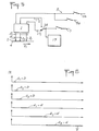
- Fig. 3 shows an alternative embodiment in which the generator 11 has three outputs 23 1 , 23 2 , 23 3 delivering three different sampling periods ⁇ , A 2 and A 3 , as shown diagrammatically in FIG. 4.
- the third frequency can, for example, be chosen to involve a sampling period of 12.8 microseconds to cover a total range of delay ranging from 3.2 milliseconds to 25, 6 milliseconds.
- the data comparator 17 is programmed to apply, by a selection means 24 (FIG. 3), always two successive frequencies to the samplers 13a and 13b.
- the selection means 24 are, for example, the number of two switches 26 controlled by the data comparator 17 to connect two of the three outputs to the two samplers 13a and 13b.
- the switches 26 are controlled by the comparator 17, assessing the position of the peak P relative to a reference point M, for example central equal to k 2 + L of the delay range corresponding to A 2 .
- a reference point M for example central equal to k 2 + L of the delay range corresponding to A 2 .
- the comparator controls the switches 26 to deliver to the sampler 13 of the standby channel the frequency corresponding to the period L1,.
- the comparator switches the role of the two delayed channels.
- the samples from the first sensor 2 are directed on a delayed channel which can comprise more than two lines supplied in parallel by involving as many own sampling frequencies.
- the delay ranges can have limits very far apart from each other and the multiplication of the number of sampling frequencies can then lead to a more complex and expensive or less efficient device.
- the switch 28 is controlled by the comparator 17, so that one or other of the sensors 3 1 , 3 2 is made active as a function of the value of the delay determined by the appreciation of the position of the peak P and of the sampling frequency in service.
- the data comparator 17 keeps the sensor 3 1 in serivce located at a distance D from the first sensor 2.
- the comparator 17 activates the sensor 3 2 located at a distance d from the first sensor 2.
- Fig. 6 illustrates the case of three sampling periods A located in a ratio 2 and two distances D, d located in a ratio 2 3 .
- the abscissa axis corresponds to the inverse of the measurable speed as opposed to the delays according to FIG. 4. Examination of this figure shows that the combination of the three frequencies and the two distances makes it possible to significantly increase the total range of measurable delays.
Landscapes
- Engineering & Computer Science (AREA)
- Physics & Mathematics (AREA)
- General Physics & Mathematics (AREA)
- Mathematical Physics (AREA)
- Computational Mathematics (AREA)
- Theoretical Computer Science (AREA)
- Mathematical Analysis (AREA)
- Mathematical Optimization (AREA)
- Pure & Applied Mathematics (AREA)
- Data Mining & Analysis (AREA)
- Software Systems (AREA)
- Algebra (AREA)
- General Engineering & Computer Science (AREA)
- Computing Systems (AREA)
- Databases & Information Systems (AREA)
- Length Measuring Devices With Unspecified Measuring Means (AREA)
- Radar Systems Or Details Thereof (AREA)
- Medicines Containing Antibodies Or Antigens For Use As Internal Diagnostic Agents (AREA)
- Paper (AREA)
- Monitoring And Testing Of Transmission In General (AREA)
- Measurement Of Resistance Or Impedance (AREA)
- Testing, Inspecting, Measuring Of Stereoscopic Televisions And Televisions (AREA)
- Measurement Of Unknown Time Intervals (AREA)
- Measurement Of Current Or Voltage (AREA)
Claims (12)
Priority Applications (1)
| Application Number | Priority Date | Filing Date | Title |
|---|---|---|---|
| AT85420060T ATE37239T1 (de) | 1984-03-28 | 1985-03-27 | Verfahren und vorrichtung zur echtzeitkorrelationsmessung von verzoegerungen zwischen sich statistisch entsprechenden elektrischen signalen. |
Applications Claiming Priority (2)
| Application Number | Priority Date | Filing Date | Title |
|---|---|---|---|
| FR8405122 | 1984-03-28 | ||
| FR8405122A FR2562259B1 (fr) | 1984-03-28 | 1984-03-28 | Procede et dispositif de mesure par correlation, en temps reel, de retards entre des signaux electriques se correspondant |
Publications (2)
| Publication Number | Publication Date |
|---|---|
| EP0161996A1 EP0161996A1 (de) | 1985-11-21 |
| EP0161996B1 true EP0161996B1 (de) | 1988-09-14 |
Family
ID=9302700
Family Applications (1)
| Application Number | Title | Priority Date | Filing Date |
|---|---|---|---|
| EP85420060A Expired EP0161996B1 (de) | 1984-03-28 | 1985-03-27 | Verfahren und Vorrichtung zur Echtzeitkorrelationsmessung von Verzögerungen zwischen sich statistisch entsprechenden elektrischen Signalen |
Country Status (8)
| Country | Link |
|---|---|
| US (1) | US4779215A (de) |
| EP (1) | EP0161996B1 (de) |
| AT (1) | ATE37239T1 (de) |
| CA (1) | CA1223071A (de) |
| DE (1) | DE3565008D1 (de) |
| FI (1) | FI79616C (de) |
| FR (1) | FR2562259B1 (de) |
| NO (1) | NO851238L (de) |
Families Citing this family (12)
| Publication number | Priority date | Publication date | Assignee | Title |
|---|---|---|---|---|
| JPS61207973A (ja) * | 1985-03-13 | 1986-09-16 | Mitsubishi Electric Corp | 相関式時間差計 |
| EP0259301A1 (de) * | 1986-01-24 | 1988-03-16 | Beloit Corporation | Strahlgeschwindigkeitsmessvorrichtung |
| US4912519A (en) * | 1987-06-19 | 1990-03-27 | Omron Tateisi Electronics Co. | Laser speckle velocity-measuring apparatus |
| GB8816348D0 (en) * | 1988-07-08 | 1988-08-10 | Kyriakis J | Non-contact measurement |
| US5142651A (en) * | 1991-10-09 | 1992-08-25 | United States Of America As Represented By The Secretary Of The Navy | Uninterrupted, enhanced-rate, event-time recorder with mixed-speed counter modules |
| US5301219A (en) * | 1991-12-18 | 1994-04-05 | The United States Of America As Represented By The Secretary Of The Navy | Uninterrupted, enhanced-rate event sequencer with mixed-speed counter modules |
| FR2749086B1 (fr) * | 1996-05-23 | 1998-08-07 | Technicatome | Dispositif de mesure optique de la vitesse d'un objet |
| US6925399B2 (en) * | 2001-03-30 | 2005-08-02 | Verizon Laboratories Inc. | Methods and systems for the estimation of the injection point of foreign signals in a network |
| WO2010099029A1 (en) | 2009-02-27 | 2010-09-02 | Cytec Technology Corp. | Epoxy compositions with improved mechanical performance |
| US10281609B2 (en) * | 2017-01-31 | 2019-05-07 | L&P Property Management Company | Multi-frequency landscape analysis system, method, and apparatus for furniture sensing |
| IL296197B2 (en) | 2019-02-19 | 2024-05-01 | Edgy Bees Ltd | Real-time video data stream latency estimation |
| CN115184631B (zh) * | 2022-06-13 | 2025-11-07 | 西南交通大学 | 一种列车速度实时估计的方法 |
Family Cites Families (13)
| Publication number | Priority date | Publication date | Assignee | Title |
|---|---|---|---|---|
| US4019038A (en) * | 1971-06-10 | 1977-04-19 | Kent Instruments Limited | Correlators |
| FR2206872A5 (de) * | 1972-10-17 | 1974-06-07 | Commissariat Energie Atomique | |
| FR2223704B1 (de) * | 1973-03-27 | 1977-09-02 | Thomson Csf | |
| DE2544821C2 (de) * | 1975-10-03 | 1985-07-25 | Ernst Leitz Wetzlar Gmbh, 6330 Wetzlar | Korrelator zur berührungslosen Messung der Geschwindigkeit mit mehreren Meßfühlern |
| FR2327553A1 (fr) * | 1975-10-10 | 1977-05-06 | Thomson Csf | Dispositif de mesure par correlation electronique du retard entre deux signaux temporels et systemes comportant un tel dispositif |
| DE2633565A1 (de) * | 1976-07-27 | 1978-02-02 | Bosch Gmbh Robert | Verfahren und einrichtung zur beruehrungslosen geschwindigkeitsmessung |
| US4100599A (en) * | 1976-12-22 | 1978-07-11 | Ncr Canada Ltd. - Ncr Canada Ltee | Method and apparatus for determining velocity of a moving member |
| DE2856032A1 (de) * | 1978-01-03 | 1979-07-12 | Coulthard John | Vorrichtung und verfahren zum messen der geschwindigkeit einer relativbewegung zwischen einem ersten koerper und einem zweiten koerper bzw. einem stroemungsmittel |
| US4285046A (en) * | 1978-06-16 | 1981-08-18 | National Research Development Corporation | Correlation method |
| SU822037A1 (ru) * | 1979-06-19 | 1981-04-15 | Ленинградский Ордена Ленина Электро-Технический Институт Им.B.И.Ульянова(Ленина) | Коррел ционный измеритель скорости |
| EP0026877B1 (de) * | 1979-10-03 | 1983-10-05 | Endress u. Hauser GmbH u.Co. | Verfahren und Anordnung zur Korrelation von zwei Signalen |
| FR2506024A1 (fr) * | 1981-05-18 | 1982-11-19 | Siderurgie Fse Inst Rech | Dispositif pour la determination de la vitesse d'un produit en defilement par la methode de correlation |
| US4604717A (en) * | 1983-02-18 | 1986-08-05 | Rca Corporation | Method and apparatus for measuring the time delay between signals |
-
1984
- 1984-03-28 FR FR8405122A patent/FR2562259B1/fr not_active Expired
-
1985
- 1985-03-27 NO NO851238A patent/NO851238L/no unknown
- 1985-03-27 FI FI851237A patent/FI79616C/fi not_active IP Right Cessation
- 1985-03-27 US US06/716,476 patent/US4779215A/en not_active Expired - Fee Related
- 1985-03-27 DE DE8585420060T patent/DE3565008D1/de not_active Expired
- 1985-03-27 EP EP85420060A patent/EP0161996B1/de not_active Expired
- 1985-03-27 AT AT85420060T patent/ATE37239T1/de not_active IP Right Cessation
- 1985-03-28 CA CA000477849A patent/CA1223071A/en not_active Expired
Also Published As
| Publication number | Publication date |
|---|---|
| FI851237A0 (fi) | 1985-03-27 |
| ATE37239T1 (de) | 1988-09-15 |
| EP0161996A1 (de) | 1985-11-21 |
| FI79616C (fi) | 1990-01-10 |
| FI79616B (fi) | 1989-09-29 |
| FI851237L (fi) | 1985-09-29 |
| DE3565008D1 (en) | 1988-10-20 |
| FR2562259A1 (fr) | 1985-10-04 |
| US4779215A (en) | 1988-10-18 |
| CA1223071A (en) | 1987-06-16 |
| NO851238L (no) | 1985-09-30 |
| FR2562259B1 (fr) | 1987-04-10 |
Similar Documents
| Publication | Publication Date | Title |
|---|---|---|
| EP0015820A1 (de) | Vorrichtung zum berührungslosen und markierungslosen Messen von linearen Geschwindigkeiten | |
| EP0760475B1 (de) | Verfahren und Vorrichtung zur Ellipsometrie mit Vielfachdetektoren | |
| EP0161996A1 (de) | Verfahren und Vorrichtung zur Echtzeitkorrelationsmessung von Verzögerungen zwischen sich statistisch entsprechenden elektrischen Signalen | |
| EP0497945A1 (de) | Panoramische kamera des ladungsübertragung typs in einem überwachungssystem | |
| WO2007042435A1 (fr) | Dispositif optique pour la mesure de vitesse de deplacement d'un objet par rapport a une surface | |
| FR2513371A1 (fr) | Procede de determination des parametres geometriques de la surface d'un objet et son dispositif de mise en oeuvre | |
| CA2122067C (fr) | Procede et dispositif d'etalonnage pour un ensemble de mesure du profil transversal d'epaisseur d'un produit plat | |
| FR2664048A1 (fr) | Procede et dispositif de detection analogique multicanal. | |
| FR2490808A1 (fr) | Interferometre et dispositif comportant cet interferometre | |
| EP3201610A1 (de) | Verfahren und system zur überprüfung transparenter wafer für elektronik, optik und opto-elektronik | |
| FR2748562A1 (fr) | Procede et dispositif a deux cameras d'observation pour des mesures tridimensionnelles d'une structure complexe | |
| FR2504838A1 (fr) | Procede de positionnement lateral d'un organe par rapport a un joint forme entre deux surfaces metalliques et presentant des discontinuites | |
| FR2780778A1 (fr) | Procede et dispositif pour la mesure de l'epaisseur d'un materiau transparent | |
| FR2591764A1 (fr) | Systeme optique de multiplexage et procede d'utilisation de ce systeme | |
| FR2749086A1 (fr) | Dispositif de mesure optique de la vitesse d'un objet | |
| FR2582388A1 (fr) | Dispositif automatique de mesure sans contact des dimensions d'une piece parallelepipedique | |
| EP0069071B1 (de) | Identifikationsverfahren eines Objekts und Messung seiner Rotation und seiner Orientation und Vorrichtung zur Ausführung dieses Verfahrens | |
| WO1986000697A1 (fr) | Procede et dispositif pour la determination de la position d'un organe mobile au moyen d'elements a proprietes optiques variables | |
| FR2545613A1 (fr) | Appareil de mesure de la vitesse d'un objet, notamment d'un aeronef | |
| FR2936614A1 (fr) | Mise au point d'un microscope a reflexion | |
| FR2688889A1 (fr) | Dispositif de mesure de la vitesse de deplacement d'un objet. | |
| FR2639433A1 (fr) | Procede pour la mesure de la puissance d'un rayonnement et montage pour l'application de ce procede | |
| EP4182679B1 (de) | Messeinrichtung zur spektroskopischen analyse einzelner sich bewegender objekte | |
| FR2780169A1 (fr) | Procede et appareil pour la mesure du repere d'un mouvement de montre mecanique | |
| WO1992019990A1 (fr) | Dispositif de detection autoreglable et autoadaptatif |
Legal Events
| Date | Code | Title | Description |
|---|---|---|---|
| PUAI | Public reference made under article 153(3) epc to a published international application that has entered the european phase |
Free format text: ORIGINAL CODE: 0009012 |
|
| AK | Designated contracting states |
Designated state(s): AT BE CH DE FR GB IT LI LU NL SE |
|
| 17P | Request for examination filed |
Effective date: 19851030 |
|
| 17Q | First examination report despatched |
Effective date: 19870330 |
|
| GRAA | (expected) grant |
Free format text: ORIGINAL CODE: 0009210 |
|
| AK | Designated contracting states |
Kind code of ref document: B1 Designated state(s): AT BE CH DE FR GB IT LI LU NL SE |
|
| REF | Corresponds to: |
Ref document number: 37239 Country of ref document: AT Date of ref document: 19880915 Kind code of ref document: T |
|
| ITF | It: translation for a ep patent filed | ||
| GBT | Gb: translation of ep patent filed (gb section 77(6)(a)/1977) | ||
| REF | Corresponds to: |
Ref document number: 3565008 Country of ref document: DE Date of ref document: 19881020 |
|
| PG25 | Lapsed in a contracting state [announced via postgrant information from national office to epo] |
Ref country code: LU Free format text: LAPSE BECAUSE OF NON-PAYMENT OF DUE FEES Effective date: 19890331 |
|
| PLBE | No opposition filed within time limit |
Free format text: ORIGINAL CODE: 0009261 |
|
| STAA | Information on the status of an ep patent application or granted ep patent |
Free format text: STATUS: NO OPPOSITION FILED WITHIN TIME LIMIT |
|
| 26N | No opposition filed | ||
| PGFP | Annual fee paid to national office [announced via postgrant information from national office to epo] |
Ref country code: AT Payment date: 19900222 Year of fee payment: 6 |
|
| PGFP | Annual fee paid to national office [announced via postgrant information from national office to epo] |
Ref country code: LU Payment date: 19900301 Year of fee payment: 6 |
|
| PGFP | Annual fee paid to national office [announced via postgrant information from national office to epo] |
Ref country code: CH Payment date: 19900314 Year of fee payment: 6 |
|
| PGFP | Annual fee paid to national office [announced via postgrant information from national office to epo] |
Ref country code: SE Payment date: 19900330 Year of fee payment: 6 Ref country code: FR Payment date: 19900330 Year of fee payment: 6 |
|
| ITTA | It: last paid annual fee | ||
| PGFP | Annual fee paid to national office [announced via postgrant information from national office to epo] |
Ref country code: NL Payment date: 19900331 Year of fee payment: 6 Ref country code: GB Payment date: 19900331 Year of fee payment: 6 Ref country code: DE Payment date: 19900331 Year of fee payment: 6 |
|
| PGFP | Annual fee paid to national office [announced via postgrant information from national office to epo] |
Ref country code: BE Payment date: 19900413 Year of fee payment: 6 |
|
| PG25 | Lapsed in a contracting state [announced via postgrant information from national office to epo] |
Ref country code: GB Effective date: 19910327 Ref country code: AT Effective date: 19910327 |
|
| PG25 | Lapsed in a contracting state [announced via postgrant information from national office to epo] |
Ref country code: SE Effective date: 19910328 |
|
| PG25 | Lapsed in a contracting state [announced via postgrant information from national office to epo] |
Ref country code: LI Effective date: 19910331 Ref country code: CH Effective date: 19910331 Ref country code: BE Effective date: 19910331 |
|
| BERE | Be: lapsed |
Owner name: CENTRE TECHNIQUE DE L'INDUSTRIE DES PAPIERS CARTO Effective date: 19910331 Owner name: CENTRE NATIONAL DE LA RECHERCHE SCIENTIFIQUE (CNR Effective date: 19910331 |
|
| PG25 | Lapsed in a contracting state [announced via postgrant information from national office to epo] |
Ref country code: NL Effective date: 19911001 |
|
| NLV4 | Nl: lapsed or anulled due to non-payment of the annual fee | ||
| GBPC | Gb: european patent ceased through non-payment of renewal fee | ||
| PG25 | Lapsed in a contracting state [announced via postgrant information from national office to epo] |
Ref country code: FR Effective date: 19911129 |
|
| REG | Reference to a national code |
Ref country code: CH Ref legal event code: PL |
|
| PG25 | Lapsed in a contracting state [announced via postgrant information from national office to epo] |
Ref country code: DE Effective date: 19920101 |
|
| REG | Reference to a national code |
Ref country code: FR Ref legal event code: ST |
|
| EUG | Se: european patent has lapsed |
Ref document number: 85420060.7 Effective date: 19911009 |