EP0162014A1 - Device and method for separating granular goods - Google Patents
Device and method for separating granular goods Download PDFInfo
- Publication number
- EP0162014A1 EP0162014A1 EP85810219A EP85810219A EP0162014A1 EP 0162014 A1 EP0162014 A1 EP 0162014A1 EP 85810219 A EP85810219 A EP 85810219A EP 85810219 A EP85810219 A EP 85810219A EP 0162014 A1 EP0162014 A1 EP 0162014A1
- Authority
- EP
- European Patent Office
- Prior art keywords
- fluidized bed
- outlet
- area
- air
- grain
- Prior art date
- Legal status (The legal status is an assumption and is not a legal conclusion. Google has not performed a legal analysis and makes no representation as to the accuracy of the status listed.)
- Granted
Links
- 238000000034 method Methods 0.000 title claims description 12
- 239000004575 stone Substances 0.000 claims abstract description 49
- 238000010276 construction Methods 0.000 claims description 3
- 239000012530 fluid Substances 0.000 claims description 3
- 239000008187 granular material Substances 0.000 claims description 2
- 238000005192 partition Methods 0.000 claims 1
- 235000013339 cereals Nutrition 0.000 abstract description 36
- 239000000463 material Substances 0.000 abstract description 30
- 238000013517 stratification Methods 0.000 description 12
- 238000000926 separation method Methods 0.000 description 9
- 206010012735 Diarrhoea Diseases 0.000 description 6
- 239000011521 glass Substances 0.000 description 4
- 238000004140 cleaning Methods 0.000 description 3
- 239000002361 compost Substances 0.000 description 3
- 230000000694 effects Effects 0.000 description 3
- 239000002994 raw material Substances 0.000 description 3
- 229910001111 Fine metal Inorganic materials 0.000 description 2
- 239000012634 fragment Substances 0.000 description 2
- 239000010903 husk Substances 0.000 description 2
- 239000002184 metal Substances 0.000 description 2
- 230000010355 oscillation Effects 0.000 description 2
- 238000005406 washing Methods 0.000 description 2
- XLYOFNOQVPJJNP-UHFFFAOYSA-N water Substances O XLYOFNOQVPJJNP-UHFFFAOYSA-N 0.000 description 2
- 241001136792 Alle Species 0.000 description 1
- 241000209140 Triticum Species 0.000 description 1
- 235000021307 Triticum Nutrition 0.000 description 1
- 240000008042 Zea mays Species 0.000 description 1
- 235000016383 Zea mays subsp huehuetenangensis Nutrition 0.000 description 1
- 235000002017 Zea mays subsp mays Nutrition 0.000 description 1
- 230000015572 biosynthetic process Effects 0.000 description 1
- 239000000470 constituent Substances 0.000 description 1
- 238000000605 extraction Methods 0.000 description 1
- 230000002349 favourable effect Effects 0.000 description 1
- 230000003179 granulation Effects 0.000 description 1
- 238000005469 granulation Methods 0.000 description 1
- 238000011086 high cleaning Methods 0.000 description 1
- 239000013072 incoming material Substances 0.000 description 1
- 230000002401 inhibitory effect Effects 0.000 description 1
- 235000009973 maize Nutrition 0.000 description 1
- 238000011169 microbiological contamination Methods 0.000 description 1
- 230000000750 progressive effect Effects 0.000 description 1
- 230000003252 repetitive effect Effects 0.000 description 1
- 239000004576 sand Substances 0.000 description 1
- 238000007873 sieving Methods 0.000 description 1
- 238000001228 spectrum Methods 0.000 description 1
- 239000010902 straw Substances 0.000 description 1
- 239000000725 suspension Substances 0.000 description 1
- 238000009423 ventilation Methods 0.000 description 1
- 239000002699 waste material Substances 0.000 description 1
Images



Classifications
-
- B—PERFORMING OPERATIONS; TRANSPORTING
- B03—SEPARATION OF SOLID MATERIALS USING LIQUIDS OR USING PNEUMATIC TABLES OR JIGS; MAGNETIC OR ELECTROSTATIC SEPARATION OF SOLID MATERIALS FROM SOLID MATERIALS OR FLUIDS; SEPARATION BY HIGH-VOLTAGE ELECTRIC FIELDS
- B03B—SEPARATING SOLID MATERIALS USING LIQUIDS OR USING PNEUMATIC TABLES OR JIGS
- B03B4/00—Separating by pneumatic tables or by pneumatic jigs
- B03B4/02—Separating by pneumatic tables or by pneumatic jigs using swinging or shaking tables
-
- B—PERFORMING OPERATIONS; TRANSPORTING
- B07—SEPARATING SOLIDS FROM SOLIDS; SORTING
- B07B—SEPARATING SOLIDS FROM SOLIDS BY SIEVING, SCREENING, SIFTING OR BY USING GAS CURRENTS; SEPARATING BY OTHER DRY METHODS APPLICABLE TO BULK MATERIAL, e.g. LOOSE ARTICLES FIT TO BE HANDLED LIKE BULK MATERIAL
- B07B4/00—Separating solids from solids by subjecting their mixture to gas currents
- B07B4/08—Separating solids from solids by subjecting their mixture to gas currents while the mixtures are supported by sieves, screens, or like mechanical elements
-
- B—PERFORMING OPERATIONS; TRANSPORTING
- B07—SEPARATING SOLIDS FROM SOLIDS; SORTING
- B07B—SEPARATING SOLIDS FROM SOLIDS BY SIEVING, SCREENING, SIFTING OR BY USING GAS CURRENTS; SEPARATING BY OTHER DRY METHODS APPLICABLE TO BULK MATERIAL, e.g. LOOSE ARTICLES FIT TO BE HANDLED LIKE BULK MATERIAL
- B07B9/00—Combinations of apparatus for screening or sifting or for separating solids from solids using gas currents; General arrangement of plant, e.g. flow sheets
- B07B9/02—Combinations of similar or different apparatus for separating solids from solids using gas currents
Definitions
- the heavy goods are then drained along a second section onto the lower vibrating table immediately below, the task of which is to read out the heavy goods and the parts with a greater specific weight (such as stones, glass, metal, etc.).
- the lower vibrating table is also equipped with a vibratory drive, which, however, generates a throwing motion against that of the upper vibrating table.
- the lower swing table is in inclined in the same direction as the upper swing table, but its swinging movement is oriented towards the higher outlet for the heaviest parts.
- the lower fluidized bed table below the intermediate floor can be designed as a channel-like depression with an air-impermeable bottom, which depression guides the heavy grain fraction into the associated outlet.
- Particularly optimal and stable operating conditions are created when the clear exhaust air cross section is divided into zones with adjustable cross sections at a distance above the upper fluidized bed table. Each should have an adjustment flap for adjusting the air volume.
- the upper fluidized bed table in a region (V) has a smooth surface with a large number of fine perforations, the region (V) of the upper table surface is air-permeable, but impermeable to the raw material. There is then a zone of coarse perforations 24 over the entire width, which can also be replaced by a passage slot across the entire width.
- the table surface In a region (A) adjoining the coarse perforations, which extends to the light material outlet 14, the table surface also has coarse, possibly medium-coarse perforations 24 'through which the various raw material fractions can fall. It is essential that the upper table does not have a sieve function, since all of the diaphragm openings are larger than the largest part of the material flow. The stratification is caused by the air flow receive. The whole lower layer falls through the rough openings. The openings can easily make up 2o to 50% of the entire table area.
Landscapes
- Engineering & Computer Science (AREA)
- Mechanical Engineering (AREA)
- Combined Means For Separation Of Solids (AREA)
- Processing Of Solid Wastes (AREA)
- Control And Other Processes For Unpacking Of Materials (AREA)
- Processing And Handling Of Plastics And Other Materials For Molding In General (AREA)
Abstract
Description
Die Erfindung betrifft eine Vorrichtung zum Trennen von Korngut in mehrere Fraktionen mit zwei schwingfähig gelagerten und in ihrer Neigung verstellbaren und von einem gemeinsamen Luftstrom durchsetzbaren Wirbelschichttischen, wobei über dem höheren Ende des oberen Wirbelschichttisches ein Einlauf für das körnige Gut angeordnet ist, dem am tieferen Ende ein Auslauf für die leichteste Kornfraktion gegenüberliegt und wobei weiter am höheren Ende des unteren Wirbelschichttisches ein Steinauslauf und am tieferen Ende ein Auslauf für die schwere Kornfraktion vorhanden ist, wobei zwischen den Wirbelschichttischen ein Zwischenboden geringerer Länge als die Wirbelschichttische angeordnet ist.The invention relates to a device for separating grain into several fractions with two oscillatingly supported and adjustable in their inclination and penetrable by a common airflow fluidized bed tables, with an inlet for the granular material is arranged above the higher end of the upper fluidized bed table, the one at the lower end there is an outlet for the lightest grain fraction and there is a stone outlet at the higher end of the lower fluidized bed table and an outlet for the heavy grain fraction at the lower end, an intermediate floor of shorter length than the fluidized bed tables being arranged between the fluid bed tables.
Für die Getreidereinigung müssen vor der Vermahlung des Korngutes sämtliche Fremdbestandteile wie auch der Schmutz entfernt werden. Die Reinigung erfolgt dabei in mehreren Etappen. Ueblicherweise werden grosse Fremdkörper mit Siebeinrichtungen ausgeschieden, wobei die Maschengrösse jeweils so gewählt wird, dass mit Sicherheit das gesamte Korngut als Durchfall gewonnen wird und alle Teile, die grösser als der Abstoss sind, abgetrennt werden. Feiner Schmutz und feiner Sand können gleichzeitig durch ein entsprechend fein gelochtes Sieb ausgeschieden werden. Auf diese Weise erhält man das eigentliche Korngut mit einem Fremdbesatz, der insbesondere aus kleinen Steinen, Glassplittern sowie Metallteilen sowie aus verschiedenem leichten Besatz (wie grosse Schalenteile, Bruchstücke von Halmen und Fremdsämereien) besteht, die alle in einem gewissen Korngrössenspektrum liegen, z.B. bei Weizensorten im Bereich von 2mm bis 6mm oder bei Mais im Bereich zwischen 5mm und 20mm. Die leichten Bestandteile werden, je nach ihrer äusseren Form und Grösse, durch spezielle Auslesetisehe (wie z.B. Paddy-Ausleser oder Leichtkornausleser) separiert. Noch bis vor etwa 20 Jahren wurde ein Grossteil des auf diese Weise auf einen bestimmten Granulationsbereich vorgesiebten und von den leichten Bestandteilen befreiten Korngutes durch ein Wasserbad geführt und dabei der anhaftende Schmutz sowie die Steine ausgeschwemmt. Die Steine konnten wegen ihrer grösseren Schwere auf diese Weise im Setzverfahren auf dem Boden der Waschmaschine gesammelt werden.For grain cleaning, all foreign matter and dirt must be removed before the grain is ground. The cleaning takes place in several stages. Large foreign bodies are usually separated out with sieve devices, the mesh size being selected in such a way that the entire grain is certainly obtained as diarrhea and all parts which are larger than the repulsion are separated off. Fine dirt and fine sand can be separated out at the same time through an appropriately finely perforated sieve. In this way, the actual grain is obtained with a foreign stock, which consists in particular of small stones, glass fragments and metal parts as well as various light stockings (such as large shell parts, fragments of straws and foreign seeds), all of which are in a certain grain size spectrum, e.g. with wheat varieties In the range of 2mm to 6mm or with maize in the range between 5mm and 20mm. Depending on their external shape and size, the light components are separated by special readout tables (such as paddy readers or light grain readers). Until about 20 years ago, a large part of the grain that had been pre-screened in this way to a certain granulation area and freed from the light constituents was passed through a water bath and the adhering dirt and stones were washed out. The stones could be collected in this way on the floor of the washing machine due to their greater weight.
Der grosse Vorteil dieser bislang in weitem Rahmen eingesetzten Reinigungsmethode liegt in ihrer sehr grossen Reinigungswirkung, der Nachteil jedoch im Anfall sehr grosser Mengen verschmutztem Waschwassers, das wegen der Gefahr einer mikrobiologischen Verseuchung nur einmal verwendet werden durfte und anschliessend ebenfalls gereinigt werden musste.The great advantage of this cleaning method, which has been widely used up to now, is its very high cleaning effect, but the disadvantage in the case of very large amounts of dirty washing water, which due to the risk of microbiological contamination could only be used once and then also had to be cleaned.
In der DE-AS 3 148 475 wird ein neuer Weg für die Trennung von Getreide und ähnlichem Korngut in einzelnen Fraktionen vorgeschlagen. Dabei werden die drei Hauptfraktionen, nämlich das Schwerkorn, das Leichtkorn und die Steine mit einer einzigen Maschine aus dem Getreide ausgelesen. Im Vordergrund steht dabei
- l. eine saubere Trennung in Schwer- und Leichtkorn, sowie
- 2. eine so gut wie vollständige Steinauslese bei einem einzigen Durchlauf durch eine Maschine, jedoch unter Anwendung von zwei übereinander angeordneten, von der gleichen Luft durchströmten Schwingtischen.
- l. a clean separation into heavy and light grain, as well
- 2. a virtually complete stone selection in a single pass through a machine, but using two vibration tables arranged one above the other, through which the same air flows.
Für das Erreichen dieser hohen qualitativen Anforderungen ist es dabei aber notwendig, jeden Arbeitsabschnitt unter optimalen Bedingungen durchzuführen. Der obere Schwingtisch dient in erster Linie einer sauberen Trennung der Leichtfraktion und weist hierfür eine längliche Form auf, wobei er vom Einlaufende zum Auslaufende in einer leichten Neigung einstellbar ist und in Richtung gegen den Auslauf hin mit einer Wurfschwingbewegung gebracht wird, damit das Produkt über die leichte Neigung kontinuierlich gefördert werden kann.To achieve these high quality requirements, however, it is necessary to carry out each work step under optimal conditions. The upper vibrating table primarily serves for a clean separation of the light fraction and has an elongated shape for this, whereby it can be adjusted at a slight incline from the inlet end to the outlet end and is brought towards the outlet with a throwing motion so that the product over the slight inclination can be continuously promoted.
Es hat sich jedoch bei der bekannten Vorrichtung gezeigt, dass es für eine gute Funktion unumgänglich ist, die Luftmenge längs der Schwingtische abschnittweise einstellen zu können. Zu diesem Zwecke wird eine Absaughaube mit schottenartiger Einteilung verwendet, wobei jedem Zwischenraum eine individuell einstellbare Luftdrossel zugeordnet ist. Damit lässt sich auf dem oberen Schwingtisch eine dem Produkt und der Durchsatzmenge speziell anpassbare Wirbelschicht erzeugen. Auf einem ersten Abschnitt des oberen Schwingtisches erfolgt durch Schwingbewegung und Luftströmung eine Konzentrierung des Schwergutes in einer Schicht unmittelbar über dem Schwingtisch und direkt über dieser wird eine zweite vom Schwergut befreite obere Schicht des Leichtgutes gebildet.However, it has been shown in the known device that it is essential for a good function to be able to adjust the air quantity in sections along the vibrating tables. For this purpose, an extraction hood with a bulkhead-like division is used, with an individually adjustable air throttle being assigned to each intermediate space. This means that a fluidized bed that can be specially adapted to the product and the throughput can be created on the upper vibrating table. On a first section of the upper vibrating table, the heavy goods are concentrated in a layer directly above the vibrating table by means of the oscillating movement and air flow, and a second upper layer of the light goods freed from the heavy goods is formed directly above this.
Längs einem zweiten Abschnitt wird sodann das Schwergut auf den unmittelbar darunter befindlichen unteren Schwingtisch abgelassen, dessen Aufgabe darin besteht, das Schwergut und die ein grösseres spezifische Gewicht aufweisenden Teile (wie Steine, Glas, Metall usw.), auszulesen. Der untere Schwingtisch ist zu diesem Zwekke ebenfalls mit einem Schwingantrieb ausgerüstet, der jedoch eine Wurfschwingbewegung entgegen der des oberen Schwingtisches erzeugt. Der untere Schwingtisch ist in die gleiche Richtung geneigt wie der obere Schwingtisch, seine Schwingbewegung ist jedoch in Richtung zu jenem höher gelegenen Auslauf für die schwersten Teile ausgerichtet.The heavy goods are then drained along a second section onto the lower vibrating table immediately below, the task of which is to read out the heavy goods and the parts with a greater specific weight (such as stones, glass, metal, etc.). For this purpose, the lower vibrating table is also equipped with a vibratory drive, which, however, generates a throwing motion against that of the upper vibrating table. The lower swing table is in inclined in the same direction as the upper swing table, but its swinging movement is oriented towards the higher outlet for the heaviest parts.
Der bauliche Aufwand dieser bekannten Vorrichtung (und damit auch ihr Preis) ist jedoch so gross, dass schon hierdurch dem Einsatz dieses Gerätes enge Grenzen gesetzt wird.However, the structural complexity of this known device (and thus also its price) is so great that the use of this device is already limited.
Darüberhinaus hat sich auch noch gezeigt, dass bei dieser Bauart nur eine beschränkte Steigerung des Produktdurchsatzes möglich ist, da bei zu grossen Durchsatzleistungen die präzise Führung der Wirbelschicht durch Steuerung der örtlichen Luftmenge nicht mehr ausreichend gut erfolgt und damit die Ausbildung der gewünschten Schichtung nicht mehr in gewünschtem Masse erzielt werden kann.In addition, it has also been shown that with this type of construction, only a limited increase in product throughput is possible, since if the throughput rates are too high, the precise guidance of the fluidized bed by controlling the local air volume is no longer sufficiently good and the desired stratification is no longer formed desired mass can be achieved.
Der Erfindung liegt nun die Aufgabe zugrunde, die aufgezeigten Nachteile der bekannten Vorrichtung zu beheben, und insbesondere eine bessere Ausnützung der gegebenen Schwingtischflächen ohne Einbusse an Trennschärfe zu erreichen.The invention is based on the object of eliminating the disadvantages of the known device, and in particular to achieve better utilization of the given vibrating table surfaces without loss of selectivity.
Die erfindungsgemässe Lösung ist dadurch gekennzeichnet, dass die Wirbelschichttische in einem starren und schwingfähig gelagertem Rahmen angeordnet sind, dem ein gemeinsamer Schwingantrieb zugeordnet ist, dessen Wurfschwingbewegung gegen den Steinauslauf gerichtet ist, und dass der untere Wirbelschichttisch vorzugsweise eine luftdurchlässige Gutauflage und parallel und mit Abstand darunter eine feingelochte Platte aufweist (Sandwich), welche gemeinsam einen angenähert konstanten Luftwiderstand über der ganzen Gutauflage ergeben, unabhängig der Gutschichtdicke auf dem unteren Tisch.The solution according to the invention is characterized in that the fluidized bed tables are arranged in a rigid and swingably mounted frame, which is assigned a common vibratory drive, the throwing motion of which is directed against the stone outlet, and that the lower fluidized bed table is preferably an air-permeable material support and parallel and at a distance below it a finely perforated plate (sandwich), which together has an approximately constant air resistance over the entire crop support result regardless of the layer thickness on the lower table.
Durch den erfindungsgemäss erreichten, nahezu konstanten apparativen Luftwiderstand kann bei guter Trennarbeit der Durchsatz wesentlich gesteigert werden. Bevorzugt wird die Summe der Lochquerschnitte der feingelochten Platte kleiner oder höchstens gleich dem zehnten Teil der Gesamtfläche der Gutauflage angenommen. Ganz besonders bevorzugt werden die beiden Schwingtische parallel angeordnet.Through the almost constant apparatus air resistance achieved according to the invention, the throughput can be increased significantly with good separation work. The sum of the hole cross sections of the finely perforated plate is preferably assumed to be less than or at most equal to the tenth part of the total area of the good support. The two vibrating tables are very particularly preferably arranged in parallel.
Ganz besonders vorteilhaft ist es, wenn beim oberen Wirbelschichttisch anschliessend an einen ersten Bereich quer über den Wirbelschichttisch eine Zone grober Lochungen angebracht sind.It is particularly advantageous if, in the upper fluidized bed table, a zone of coarse perforations is attached to a first area across the fluidized bed table.
Ferner wird bevorzugt, anschliessend an die Zone grober Lochungen eine Schwelle quer über den Wirbelschichttisch vorzusehen, wobei die Schwelle wenigstens eine Höhe des Ein- bis Zweifachen der mittleren Kornabmessung beträgt, höchstens aber etwa die Hälfte der zu erwartenden Schichtdicke.Furthermore, it is preferred to provide a threshold across the fluidized bed table subsequent to the zone of coarse perforations, the threshold being at least one to two times the average grain size, but at most approximately half the layer thickness to be expected.
Bevorzugt wird der obere Wirbelschichttisch in Richtung vom Einlauf gegen den Auslauf für die leichteste Kornfraktion in zwei sich folgende Bereiche unterschiedlicher Lochung eingeteilt, derart, dass die Steine und schwere Kornfraktion nur in den Bereich grober Lochungen durch den Wirbelschichttisch hindurchfallen können.The upper fluidized bed table is preferably divided in the direction from the inlet towards the outlet for the lightest grain fraction into two consecutive areas of different perforations such that the stones and heavy grain fraction can only fall through the fluid bed table in the area of coarse perforations.
Damit auch eine saubere Trennung der Leichtfraktion erreicht werden kann, werden im zweiten Bereich des oberen Wirbelschichttisches gegeneinander verstellbare Seitenwände für die Arbeitsfläche des oberen Wirbelschichttisches vorgesehen, welche mit ihren dem Auslauf für die leichteste Kornfraktion zugewandten Enden gegeneinander schwenkbar sind, zum Zweck, die wirksame Fläche des oberen Wirbelschichttisches gegen den Auslauf für die leichteste Kornfraktion keilförmig zu verjüngen.So that a clean separation of the light fraction can also be achieved, in the second area of the upper fluidized bed table, mutually adjustable side walls are provided for the working surface of the upper fluidized bed table, which with its outlet for the lightest grain fraction facing ends are pivotable against each other, for the purpose of tapering the effective surface of the upper fluidized bed table against the outlet for the lightest grain fraction.
Sehr vorteilhaft wird ferner unter den zweiten Bereich des Wirbelschichttisches eine gegen den Auslauf für die Steine abfallende, und unterhalb dem Schlitz bzw. einer Zone grober Lochungen vorbeiführende Rutsche vorgesehen, wobei die Rutsche zwischen den ersten Bereich und der anschliessenden Zone grober Lochungen bzw. Schlitzöffnung verstellbar ist.Also very advantageously, a slide falling against the outlet for the stones and passing beneath the slot or a zone of coarse perforations is provided under the second region of the fluidized bed table, the slide being adjustable between the first region and the adjoining zone of coarse perforations or slot opening is.
Bevorzugt endet die Rutsche etwa in mittlerer Höhe zwischen den beiden Wirbelschichttischen, und über die Länge des unteren Wirbelschichttisches etwa in dem mittleren Drittel.The slide preferably ends approximately at a medium height between the two fluidized bed tables, and in the middle third over the length of the lower fluidized bed table.
Bei einem weiteren besonders bevorzugten Ausgestaltungsgedanken wird in dem dem ersten Bereich folgenden Bereiche in Zwischenboden angeordnet, der gegen das tiefere Ende des unteren Wirbelschichttisches geneigt ist. Der Zwischenboden wird dabei so angeordnet, dass er die Wirbelschichttische unter einem Winkel von 25° bis 45° schneidet, und dass die Neigung der Wirbelschichttische mit Bezug auf die Horizontale 5° bis 10° beträgt.In another particularly preferred embodiment, the intermediate area is arranged in the area following the first area, which is inclined towards the lower end of the lower fluidized bed table. The intermediate floor is arranged so that it cuts the fluidized bed tables at an angle of 25 ° to 45 °, and that the inclination of the fluidized bed tables is 5 ° to 10 ° with respect to the horizontal.
Bevorzugt ist der Zwischenboden durch eine Vielzahl von Flachprofilen gebildet, die um ihre Längsmittelachse drehbar im Gehäuse gelagert sind, so dass durch Abklappen oder durch Zusammenschalten eine entsprechende Mischfraktion eingestellt werden kann.The intermediate base is preferably formed by a multiplicity of flat profiles which are mounted in the housing so as to be rotatable about their longitudinal central axis, so that a corresponding mixed fraction can be set by folding down or interconnecting.
Auf diese Weise können sehr scharf drei Fraktionen
- - eine schwere Kornfraktion
- - eine Mischfraktion sowie
- - eine Leichtfraktion
gewählt werden.This way, three fractions can be very sharp
- - a heavy grain fraction
- - a mixed fraction as well
- - a light fraction
to get voted.
Dabei können die Flachprofile so eingestellt werden, dass sie bei koplanarer Ausrichtung einander berühren. Sie können aber auch so abgestuft werden, dass zwischen den Stufen eine Luftdurchtrittsöffnung entsteht.The flat profiles can be set so that they touch each other when coplanar. However, they can also be graded so that an air passage opening is created between the steps.
In Weiterführung dieser Gedanken kann der untere Wirbelschichttisch unterhalb des Zwischenbodens als rinnenartige Vertiefung mit luftundurchlässigem Boden ausgebildet werden, welche Vertiefung die schwere Kornfraktion in den zugehörigen Auslauf führt. Ganz besonders optimale und auch stabile Betriebsbedingungen entstehen, wenn mit Abstand über dem oberen Wirbelschichttisch der lichte Abluftquerschnitt in im Querschnitt verstellbare Zonen unterteilt wird. Dabei soll jeder eine Einstellklappe für die Einstellung der Luftmenge aufweisen.In continuation of these ideas, the lower fluidized bed table below the intermediate floor can be designed as a channel-like depression with an air-impermeable bottom, which depression guides the heavy grain fraction into the associated outlet. Particularly optimal and stable operating conditions are created when the clear exhaust air cross section is divided into zones with adjustable cross sections at a distance above the upper fluidized bed table. Each should have an adjustment flap for adjusting the air volume.
Für ein optimales Funktionieren des Schichttisches wird dieser mit einer grossen Anzahl feiner Lochungen, jedoch einer glatten Oberfläche, ausgestattet. Mit dieser Massnahme wird aufgrund der aufwärts fördernden Wurfschwingbewegung eine starke Hemmwirkung für die auf den oberen Schwingtisch unmittelbar aufliegende Produktschicht erreicht. Auf dem oberen Tisch entsteht somit ein fast scherenartiger Effekt, der bewirkt, dass alle schweren Teile, die einmal in die untere am schnellen Abfliessen gehinderte Schicht eingetreten sind, weder durch die Luft noch durch die Vibrationsbewegung wieder in die obere Schichtung zurückspringen können. Durch diese letzte Massnahme wird der Schichteffekt auf dem oberen Tisch stark intensiviert. Dies erlaubt, die benötigte Luftmenge wie auch die Schwingenergie optimal auszunützen, so dass nun auf derselben Tischfläche eine wesentlich grössere Durchsatzleistung verarbeitet bzw. eine saubere Schichtung über eine sehr kurze Tischlänge abgeschlossen werden kann.For an optimal functioning of the shift table, it is equipped with a large number of fine perforations, but a smooth surface. With this measure, a strong inhibiting effect is achieved for the product layer lying directly on the upper vibrating table due to the upward-promoting throwing swing movement. This creates an almost scissor-like effect on the upper table, which means that all heavy parts that have once entered the lower layer, which is prevented from flowing away quickly, cannot jump back into the upper layer either through the air or through the vibration movement. This last measure intensifies the layer effect on the upper table. This allows the be To optimally utilize the required amount of air as well as the vibration energy, so that a significantly higher throughput can now be processed on the same table surface or a clean layering over a very short table length can be completed.
In Weiterführung dieses Gedankens wird der Steinauslesetisch als Gutauflage ein luftdurchlässiges, gutundurchlässiges Maschengitter parallel und mit Abstand darunter eine feingelochte Platte, dazwischen einen schottenartigen Aufbau (Sandwich), derart ausgebildet, dass der untere Schwingtisch mit der fein gelochten Platte einen angenähert konstanten Luftwiderstand über der ganzen Gutauflage ergibt, unabhängig von der Gutschichtdicke auf dem unteren Wirbelschichttisch. Besonders bevorzugt weist der Steinauslesetisch eine rauhe Oberfläche auf, derart, dass die schweren Teile aufgrund der Aufschwingbewegung nach dem höher liegenden Auslauf für die schweren Teile gefördert werden. Der für den oberen Schwingtisch ausgenützte Hemmeffekt gegen die Fliessvorrichtung des Produktes gerichtete Wurfschwingbewegung wird hier mit der rauhen Oberfläche des Steinauslesetisches zur eigentlichen Berg-auf-Förderung der unteren Schicht, die angereichert ist mit schwersten Bestandteilen, ausgenutzt.In continuation of this idea, the stone reading table is designed as a good support, an air-permeable, well-impermeable mesh grid parallel and at a distance below a finely perforated plate, in between a bulkhead-like structure (sandwich), such that the lower swing table with the finely perforated plate has an approximately constant air resistance over the whole Good support results regardless of the thickness of the bed on the lower fluidized bed table. The stone reading table particularly preferably has a rough surface, such that the heavy parts are conveyed for the heavy parts due to the swinging movement after the higher outlet. The throwing swing movement used for the upper vibrating table against the flow device of the product is used here with the rough surface of the stone reading table for the actual mountain-up conveying of the lower layer, which is enriched with the heaviest components.
Beurteilt man die Arbeitsweise der neuen Vorrichtung, so fällt einem doch ein neuer Kerngedanke auf. Der besondere Kernpunkt liegt nun dabei in der Tatsache, dass dem Produkt sowohl auf den oberen Tisch in einem ersten Bereich, als auch auf den ganzen unteren Tisch die grösstmögliche Flächenausbreitung gegeben wird, jedoch so, dass die gesamte Arbeitsfläche einheitlich mit Produkt beaufschlagt ist und quer zu der Strömungsrichtung an jeder Stelle ein nahezu identischer Arbeitsablauf sich einstellt. Der Arbeitsablauf wird von Beginn des Produkteintrittes auf die jeweilige Tischfläche fortschreitend und konsequent durchgeführt bis zu der Stelle, an der die entsprechende Arbeitsstufe abgeschlossen ist. Das bedeutet für den oberen Schwingtisch, dass das Produkt bereits bei Tischanfang in einer gleichmässigen Schichtung über der ganzen Breite des Tisches aufgegeben wird und die Schichtung konsequent bis zur Uebergabe der unteren Schicht, an den darunter befindlichen Steinauslesetisch, ungestört vervollkommnet wird. Erst bei vollständig erreichter Schichtung wird die ganze, mit den Schwerteilen angereicherte Unterschicht im ganz kurzen Abschnitt als Durchfall abgezogen. Auf den unteren Siebtisch wird nochmals sinngemäss das Produkt möglichst gleichmässig über der ganzen Breite des Steinauslesetisches schleierartig in einer definierten Zone aufgegeben. Von dieser Zone aus bildet sich wiederum sowohl in Richtung zum höher gelegenen Tischende als auch zum tiefer gelegenen Tischende über der gesamten Fläche eine überraschend gleichmässige Schichtung bzw. Wirbelschicht aus. Der kurze Abschnitt des Durchfalles für die Steinauslese ist bevorzugt höchstens ein Fünftel des ersten produktundurchlässigen Bereiches.If you evaluate the operation of the new device, you will notice a new core idea. The particular key point now lies in the fact that the product is given the largest possible area spread both on the upper table in a first area and on the entire lower table, but in such a way that the entire work surface is uniformly exposed to the product and across an almost identical workflow occurs at every point to the direction of flow. The workflow is from Beginning of the product entry on the respective table surface progressively and consistently carried out to the point at which the corresponding work step is completed. For the upper vibrating table, this means that the product is applied evenly at the start of the table in a uniform layering over the entire width of the table and the layering is consistently perfected undisturbed until the lower layer is transferred to the stone reading table underneath. Only when the stratification has been completely reached is the entire underlayer, enriched with the heavy parts, pulled off in the very short section as diarrhea. On the lower sieve table, the product is again applied in a defined zone as uniformly as possible across the entire width of the stone reading table. From this zone, a surprisingly even stratification or fluidized bed is formed both in the direction of the higher table end and the lower table end over the entire surface. The short section of the diarrhea for the stone selection is preferably at most one fifth of the first product-impermeable area.
Sicher wird zu diesem guten Resultat auch die Verwendung der feingelochten Platte sowie des sandwichartigen Aufbaues des Steinauslesers wesentlich beitragen, da dadurch zumindest auf der unteren Tischfläche über der ganzen Oberfläche eine gleichmässige Luftgeschwindigkeit sich einstellt.The use of the finely perforated plate and the sandwich-like structure of the stone reader will certainly also make a significant contribution to this good result, since this results in a uniform air speed at least on the lower table surface over the entire surface.
Bei einer weiteren bevorzugten Ausführungsform wird die obere Tischfläche im Bereich der Produkteinspeisung luftdurchlässig ausgebildet und ein kurzes Stück mit Abstand über der Tischfläche abgedeckt zur Bildung eines Luftstromes in Richtung des eintretenden Gutstromes. Auf diese Weise erhält das frisch auf den Tisch aufzugebende Gut an der Eintrittsstelle gleichsam einen Stoss, so dass trotz Wurfschwingbewegung, die das Gut in umgekehrter Richtung nach oben werfen will, im Bereich des Einlaufes eine eindeutige Förderung nach dem tiefer gelegenen Tischende.In a further preferred embodiment, the upper table surface in the area of the product feed is made air-permeable and a short distance at a distance above the table surface is covered to form an air flow in the direction of the incoming material current. In this way, the goods to be freshly placed on the table receive a push at the entry point, so that despite the throwing swing movement that wants to throw the goods in the opposite direction upwards, there is a clear conveyance in the area of the inlet after the lower end of the table.
Die Erfindung betrifft ferner ein Verfahren zum Auslesen von Schwergut, insbesondere Steinen aus Getreide über zwei zu den Auslässen geneigten, mit der gleichen Luft durchströmten und gemeinsam in Schwingung versetzten Tischflächen, wobei beiden eine Wurfschwingbewegung in Richtung auf das höher liegende Tischende aufgeprägt wird.The invention further relates to a method for reading out heavy goods, in particular stones from cereals, over two table surfaces inclined to the outlets, through which the same air flows and together set in motion, both of which are impressed by a throwing motion in the direction of the higher table end.
Das erfindungsgemässe Verfahren ist dadurch gekennzeichnet, dass das Gut auf dem oberen Schwingtisch über einen ersten Bereich (V) geschichtet, und von dem Gutstrom 20 bis 60% mit allem Schwergut als Gutzufuhr schleierartig auf den mittleren Bereich der unteren Tischfläche abgeworfen wird. Dadurch wird nicht nur der Schichtvorgang genau definiert, sondern auch eine eindeutige Bedingung geschaffen für das Abziehen der mit den schweren Beimengungen angereicherten unteren Schicht. Dabei ist es sehr wesentlich, dass ein wesentlicher Teil des gesamten Gutes, d.h. 20 bis 60%, auf den unteren, den Steinausleser bildenden Tisch "gebündelt" übergeben wird. Ganz besonders wichtig ist ferner die Tatsache, dass bei dem Betrieb jeder Schwingtisch wenigstens 20% oder mehr des Gutes erhält und somit eine echte Wirbelschicht sich ausbildet, bzw. eine Art Produktteppich hergestellt wird und so die Vorraussetzung für eine echte Schichtung gegeben wird.The method according to the invention is characterized in that the material on the upper vibrating table is layered over a first area (V), and from the
Die Erfindung schlägt weiter vor, die Gutzufuhr für den Steinausleser in dessen mittleren Bereich vorzunehmen, wobei das Gut örtlich begrenzt schleierartig abgeworfen wird. Im Vordergrund steht dabei, dass ein wesentlicher Teil des Gutes über einen kurzen Bereich abgezogen und schleierartig dem unteren Tisch in einem mittleren Bereich vorzugsweise dem mittleren Drittel übergeben werden.The invention further proposes to carry out the supply of goods for the stone reader in the central region thereof, the material being thrown off in a locally veil-like manner. The focus here is on the fact that a substantial part of the goods are drawn off over a short area and transferred to the lower table in a middle area, preferably the middle third, like a veil.
Es hat sich bei dem erfindungsgemässen-Verfahren gezeigt, dass die Schichtung als solche über eine verhältnismässig kurze Wegstrecke bzw. während einer kurzen Zeitspanne nahezu vollkommen durchgeführt werden kann. Nach Durchlauf etwa der halben oberen Tischfläche ist die Schichtung vollständig abgeschlossen. Dieser Vorgang kann auch mit einem grossen Massestrom kontinuierlich durchgeführt werden, dabei wird die Schichtung bei Vergrösserung des Produktdurchsatzes sogar noch verbessert.It has been shown in the method according to the invention that the stratification as such can be carried out almost completely over a relatively short distance or over a short period of time. The layering is completely completed after passing through about half of the upper table surface. This process can also be carried out continuously with a large mass flow; the stratification is even improved as the product throughput increases.
Die Erfindung ermöglicht zweierlei: Erstens wird aus dem gesamten Gutstrom gleichzeitig ein Teilstrom abgezweigt und auf den Steinauslesetisch abgegeben. Dies bewirkt anders, als bei bekannten Verfahren, von vornherein eine Entlastung des Steinauslesetisches von einem Teil des Gutes, bzw. von der leichten Fraktion. Dies liesse sich z.B. nicht erreichen, wenn während der Schichtenbildung gleichzeitig ein Siebvorgang durchgeführt wird, bei welchem gleichermassen sowohl schwere Teile wie kleine Teile durch das Sieb nach unten fallen. Zum zweiten wird erfindungsgemäss aber auch noch erreicht, dass am Steinauslesetisch nun an jeder Stelle klare Ablaufbedingungen vorliegen, wobei auch auf dem Steinauslesetisch wiederum eine Schichtung stattfindet. Die Schichtung wird beim Steinausleser jedoch durch die Wurfschwingbewegung und der entgegengesetzten bzw. tischaufwärts gerichteten Bewegung mit nur noch einem kleinen Teil des ursprünglichen Gutstromes durchgeführt, da auf dem Steinauslesetisch die grössere Menge direkt nach unten fliesst. Auf dem Steinauslesetisch findet ein dauernder Austausch der verschiedenen Anteile zwischenThe invention enables two things: Firstly, a partial flow is simultaneously branched off from the entire crop flow and delivered to the stone reading table. In contrast to known methods, this causes the stone reading table to be relieved of part of the goods or the light fraction from the outset. This could not be achieved, for example, if a sieving process is carried out at the same time during the layer formation, in which both heavy parts and small parts fall down through the sieve. Secondly, according to the invention, however, it is also achieved that there are now clear drainage conditions at every point on the stone reading table, with stratification again taking place on the stone reading table. However, the stratification in the stone picker is countered by the throwing swing movement and the set or table upward movement carried out with only a small part of the original crop flow, since the larger amount flows directly downwards on the stone selection table. On the stone reading table there is a constant exchange of the different parts between
der unteren und der oberen Schicht statt. Durch die beiden ausgeprägten Strömungen
- - schwerste Teile tischaufwärts und
- - leichtere Fraktionen tischabwärts
werden alle verhältnismässig leichteren Teile der oberen abschwimmenden Schicht sofort nach unten dem Auslauf für das Korngut zugeführt.the lower and upper layers instead. Through the two distinct currents
- - heaviest parts up the table and
- - lighter fractions down the table
all relatively lighter parts of the upper floating layer are immediately fed down to the grain outlet.
Bevorzugt werden 20 bis 50% des Gutstromes mit dem Schwergut auf den mittleren Bereich der unteren Tischfläche übergeben. In den meisten Fällen wird angestrebt, dass weniger als 50% des Gutstromes auf den Steinauslesetisch abgeworfen werden. Besonders vorteilhaft ist ferner, wenn das schleierartig von der oberen Tischfläche auf die untere Tischfläche abfallende Gut mit einer starken Luftströmung durchblasen wird. Dadurch wird der abfallende Gutschleier etwas aufgelockert, so dass fast jedes Korn einzeln auf die Wirbelschicht des Steinauslesetisches auftrifft. Am oberen Ende des unteren Tisches wird bevorzugt direkt über der Tischfläche ein Luftstrahl zur Begrenzung der Wirbelschicht erzeugt. Ganz besonders bevorzugt wird die Gutzufuhr zur unteren Tischfläche über eine Rutsche in Bezug auf die Fliessrichtung auf den oberen Tisch in entgegengesetzter Richtung umgelenkt und abgeworfen. Durch diese Massnahme wird das Gut zusätzlich aufgelockert und ermöglicht auch, dass die Luft durch die zwei Tischflächen durchgesaugt wird, und im Bereich der Rutsche entgegengesetzt zur Gutbewegung, umgelenkt wird.Preferably 20 to 50% of the material flow with the heavy material is transferred to the middle area of the lower table surface. In most cases, the aim is that less than 50% of the material flow is thrown onto the stone reading table. It is also particularly advantageous if the material falling from the upper table surface to the lower table surface is blown with a strong air flow. This loosens up the falling veil of material so that almost every grain hits the fluidized bed of the stone reading table individually. At the upper end of the lower table, an air jet for delimiting the fluidized bed is preferably generated directly above the table surface. The supply of material to the lower table surface is very particularly preferably deflected and thrown off in a direction opposite to the upper table by means of a slide in relation to the flow direction. This measure loosens the material and also allows the air to pass through the two tables is sucked through surfaces, and is diverted in the area of the slide opposite to the good movement.
Die Erfindung wird nun anhand einiger Ausführungsbeispiele in weiteren Einzelheiten erläutert. Es zeigen
- Fig. 1 einen Vertikalschnitt (im Prinzip) durch eine erfindungsgemässe Vorrichtung,
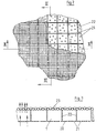
- Fig. 2 einen Teilausschnitt aus einer Draufsicht auf den unteren Wirbelschichttisch, aus der Vorrichtung nach der Fig. 1,
- Fig. 3 den Schnitt III-III aus Fig. 2,
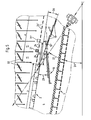
- Fig. 4 schematisch den Materialfluss in der erfindungsgemässen Vorrichtung gemäss Fig. 1,
- Fig. 5 ein Detailausschnitt der Vorrichtung aus der Fig. 1,
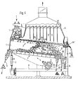
- Fig. 6 ein weiteres Ausführungsbeispiel einer erfindungsgemässen Vorrichtung,
- Fig. 7 eine entsprechende Darstellung der Fig. 1 eines weiteren Ausführungsbeispieles einer erfindungsgemässen Vorrichtung.
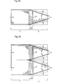
- Fig. 8a einen Grundriss des oberen Schichttisches,
- Fig. 8b eine Doppelausführung für grosse Durchsatzleistungen.
- 1 is a vertical section (in principle) through an inventive device,
- 2 shows a partial section from a top view of the lower fluidized bed table, from the device according to FIG. 1,
- 3 shows the section III-III from FIG. 2,
- 4 schematically shows the material flow in the device according to the invention according to FIG. 1,
- 5 shows a detail of the device from FIG. 1,
- 6 shows a further exemplary embodiment of a device according to the invention,
- FIG. 7 shows a corresponding representation of FIG. 1 of a further exemplary embodiment of a device according to the invention.
- 8a is a plan view of the upper layer table,
- Fig. 8b a double version for high throughputs.
Die in Fig. 1 gezeigte Vorrichtung weist einen Einlauf 1 für das körnige Gut bzw. das Rohgut auf, welches direkt auf das höherliegende Ende eines oberen Wirbelschichttisches 2 fällt. Ein unterer Wirbelschichttisch 3 ist mit Abstand unter dem oberen, in einen gemeinsamen Rahmen 4 eingebaut. Beide Tische werden mit dem Rahmen 4 durch einen Schwingantrieb 5 in Schwingung versetzt, wozu sie mittels einer Feder 6 bzw. einer in der Höhe einstellbaren Schwingstütze 7 auf einem Gestell 8 gelagert sind. Am Gestell 8 sind ferner zwei seitliche Wandteile 9 befestigt, auf die eine an eine Ansaugleitung angeschlossene Ablufthaube 10 aufgesetzt ist. Diese ist durch Querwände in einzelne Zonen 11 unterteilt. Jede Zone 11 weist eine Lufteinstellklappe 32auf, so dass in jeder einzelnen Zone die Grösse des Strömungsquerschnittes individuell einstellbar ist. Der obere Wirbelschichttisch 2 weist einen Leichtgutauslauf 14 auf, wogegen dem unteren Wirbelschichttisch 3 ein Steinauslauf 13, sowie je ein Auslauf 15 für die schwere Fraktion und ein Auslauf 16 für die mittlere Mischfraktion zugeordnet sind.The device shown in Fig. 1 has an inlet 1 for the granular or the raw material, which directly on the higher end of an upper vortex shift table 2 falls. A lower fluidized bed table 3 is installed at a distance below the upper one in a common frame 4. Both tables are set in motion with the frame 4 by an
Weiter weist der obere Wirbelschichttisch in einem Bereich (V) eine glatte Oberfläche mit einer grossen Anzahl feiner Lochungen auf, der Bereich (V) der oberen Tischfläche ist zwar luftdurchlässig, für das Rohgut aber undurchlässig. Anschliessend befindet sich über die ganze Breite eine Zone grober Lochungen 24, welche auch durch einen Durchtrittschlitz quer über die ganze Breite ersetzt sein können. In einem, an die groben Lochungen anschliessenden Bereich (A), der sich bis zum Leichtgutauslauf 14 erstreckt, weist die Tischfläche ebenfalls grobe, gegebenenfalls mittelgrobe Lochungen 24' auf, durch welche die verschiedenen Rohgutfraktionen hindurchfallen können. Wesentlich ist dabei, dass der obere Tisch keine Siebfunktion hat, da alle Durchfallöffnungen grösser sind als die grössten Teile des Gutstromes. Die Schichtung wird durch den Luftstrom erhalten. Durch die groben Oeffnungen fällt gleichsam die ganze untere Schicht. Die Oeffnungen können dabei ohne weiteres 2o bis 50% der ganzen Tischfläche ausmachen.Furthermore, the upper fluidized bed table in a region (V) has a smooth surface with a large number of fine perforations, the region (V) of the upper table surface is air-permeable, but impermeable to the raw material. There is then a zone of
Der untere Wirbelschichttisch 3 ist auf der ganzen Fläche luftdurchlässig, jedoch undurchlässig für das herabfallende Gut. Wie die Fig. 2 und 3 zeigen, weist er eine untere Lochplatte 20 mit einer Lochung 21 auf, über der ein paralleles, Machengitter 23 angeordnet ist. Im Zwischenraum zwischen der Lochplatte 20 und dem Maschengitter 23 sind schachbrettartig Schottenwände 22 vorgesehen, welche den Durchströmungsquerschnitt für die Luft in rechteckige Kanäle unterteilen.The lower fluidized bed table 3 is permeable to air over the entire surface, but impermeable to the falling material. As FIGS. 2 and 3 show, it has a lower
Wesentlich für das Ausscheiden einer mittleren Fraktion ist ein Boden 17, der die Abtrennung mittelschwerer Körner aus dem durch den oberen Wirbelschichttisch 2 hindurchfallenden Gut erlaubt. Der Boden 17 besteht aus einer Anzahl Klappen 18, die sich von einer Längswand des Rahmens 4 zur anderen erstrecken und in diesen Längswänden um ihre Längsmitte schwenkbar gelagert sind. Die Länge des beim Auslauf 16 endenden Bodens 17 und damit der mengenmässige Anteil der mittelschweren Fraktion am herabfallenden Gut wird durch die Anzahl der koplanar aneinander geschwenkten Klappen 18 bestimmt.A
Ein wesentlicher Punkt liegt weiter in der Verwendung einer Rutsche 19, welche in der Neigung und in der Länge einstellbar sein kann. Die Rutsche 19 befördert den mit den Steinen sowie mit den schwersten Körner angereicherten Gutanteil, der durch den oberen Wirbelschichttisch 2 anschliessend an den ersten produktenddurchlässigen Bereich hindurchfällt gegen den Steinauslauf 13.Another essential point is the use of a
In Fig. 4 ist die Vorrichtung hinsichtlich ihrer Funktionsweise bzw. des darin auftretenden Materialflusses nochmals dargestellt. Das Produkt tritt beim Einlauf 1 in die Vorrichtung und wird in einem ersten Bereich des oberen Wirbelschichttisches 2 geschichtet. Die Steine unten, die Leichtkörper (einschliesslich Spelzen, Sämerein u.dgl.) oben und die übrigen Körner, entsprechend ihrer Schwebegeschwindigkeit dazwischen. Im dargestellten Beispiel wird etwa im mittleren Bereich die unterste Schicht durch die groben Lochungen 24 auf die Rutsche 19 abgeworfen und in Richtung des Pfeiles 25 gegen den Steinauslauf 13 gefördert. Die Steine werden beim Steinauslauf 13 ausgetragen. Die Körner schwimmen bis zum Auslauf 16 und werden dort ausgetragen. Vom Rest des Gutes fällt in der zweiten Hälfte des Bereiches (A) ein Teil auf den Boden 17. Von der ersten Hälfte des Bereiches (A) kann bei offener Stellung von Klappen 18 ein Teil noch auf den unteren Wirbelschichttisch 3 fallen. Der Durchfall der zweiten Hälfte wird danach durch den Auslauf 16, der Durchfall der ersten Hälfte durch den Auslauf 15 ausgetragen. Im Gegensatz zu Fig. 1 (Auslauf 14) wird der Leichtgutauslauf 14' direkt ausgesondert.FIG. 4 shows the device again with regard to its mode of operation and the material flow occurring therein. The product enters the device at the inlet 1 and is layered in a first region of the upper fluidized bed table 2. The stones below, the light bodies (including husks, seeds and the like) above and the other grains, according to their speed of suspension in between. In the example shown, the lowermost layer is thrown through the
Besonders interessant für die Gesamtfunktion der Vorrichtung ist die Möglichkeit der zweifachen Luftsteuerung der Saugluft. Einerseits wird mit der besonderen Aufbauweise des unteren Wirbelschichttisches 3 eine gleichmässige Durchlüftung auf der ganzen Tischfläche erreicht, unabhängig von der Schichtdicke des Korngutes. Die Funktion des oberen Wirbelschichttisches 2 verlangt für die sich von links nach rechts folgenden Bereiche, d.h. die für Produktschichtung, für das Abwerfen der Steine und der schweren Kornfraktion sowie für die Trennung in mittelschweres und leichtes Gut, jeweils eine spezifisch gesteuerte und angepasste Luftmenge, was mittels der Einstellklappen 32 einstellbar ist.The possibility of double air control of the suction air is particularly interesting for the overall function of the device. On the one hand, with the special construction of the lower fluidized bed table 3, uniform ventilation is achieved over the entire table surface, regardless of the layer thickness of the grain. The function of the upper fluidized bed table 2 requires for the areas that follow from left to right, ie for product stratification, for throwing off the stones and the heavy grain fraction, and for separating into medium-weight and light goods, each have a specifically controlled and adjusted amount of air, which can be adjusted by means of the adjusting flaps 32.
Ein ganz wesentlicher Punkt aber neben der Luftführung und einer entsprechenden Produktlenkung liegt in der Lenkungsmöglichkeit des Gutes durch den Einbau der Rutsche 19 und des Bodens 17. Diese beiden Einbauten lassen eine sehr präzise Führung und gegebenenfalls Feinregulierung der Produktströme zu.A very important point, however, in addition to the air routing and a corresponding product steering, is the possibility of directing the goods by installing the
Bei dem in Fig. 5 gezeigten Ausschnitt aus Fig. 1 sind der Boden 17 und die Rutsche 19 vergrössert dargestellt. Die beiden Wirbelschichttische 2 und 3 sind vorzugsweise unter sich parallel und mittels der Schwingstütze 7 mit Bezug auf eine horizontale Ebene (Winkel 26) zwischen 5° und 10° verstellbar. Die Schwingrichtung des Schwingantriebes 5 schneidet die Ebenen der Wirbelschichttische 2 und 3 unter einem Winkel von 25° bis 45° (Winkel 27), wogegen die Ebene des Bodens 17 bzw. die Ebene der Rutsche 19 mit jenen der Wirbelschichttische 2 und 3 je einen Winkel von 5° bis 40° (Winkel 28) bzw. je einen Winkel von 0° bis 65° (Winkel 29) einschliessen. Beim Betrieb der Vorrichtung wird die Neigung des unteren Wirbelschichttisches 3 derart eingestellt, dass sie am günstigsten für die Ausscheidung der Steine durch den Auslauf 13 ist. Damit dürfte aber in der Regel die Neigung des oberen Wirbelschichttisches 2 (da die beiden Tische durch den Rahmen 4 fest miteinander verbunden sind) für das Trennen der übrigen Fraktionen weniger optimal sein. Mit der Längenverstellbarkeit des Bodens 17 kann insbesondere bei starken Durchsatzunterschieden die Menge der durch den Auslauf 16 abzuführenden Mischfraktion zulasten der durch den Auslauf 15 abzuführenden schweren Kornfraktion vergrössert oder verkleinert werden. Durch die Neigung des Bodens 17 kann das darauf fallende Gut trotz entgegengesetzt wirkender Schwingrichtung des Schwingantriebs 5 verzögerungsfrei in den Auslauf 16 abfliessen.In the section from FIG. 1 shown in FIG. 5, the bottom 17 and the
Wie Fig. 6 zeigt, kann der Boden 17 auch stufenförmig gestaltet sein, wobei im Bereich der Stufen Saugluft vom unteren Wirbelschichttisch 3 zum oberen strömen kann, was einen gleichmässigen Luftdurchfluss durch diesen erleichtert; die leichteste Fraktion (Schalen, Spelzen usw.) wird als Abstoss des oberen Schichttisches 2 durch einen Auslass 14' ausgetragen.As shown in FIG. 6, the bottom 17 can also be designed in a step-like manner, suction air being able to flow from the lower fluidized bed table 3 to the upper one in the area of the steps, which facilitates a uniform air flow through it; the lightest fraction (shells, husks, etc.) is discharged as an expulsion of the upper layer table 2 through an outlet 14 '.
Die Rutsche 19 liegt mit ihrem oberen Ende unter dem an den Vorschichtbereich des oberen Wirbelschichttisches 2 unmittelbar anschliessenden Bereich (D), durch den nahezu alle Steine hindurchfallen, um diese möglichst in den mittleren Bereich des unteren Tisches 3 zu führen. Vorzugsweise wird die Rutsche 19 im Rahmen 4 längsverschiebbar gelagert, so dass ihr oberes Ende in grössere oder kleinere Entfernung vom Ende des Vorschichtbereiches des oberen Wirbelschichttisches 2 gebracht werden kann. Damit wird es möglich, praktisch sämtliche Steine mit der Rutsche 19 abzufangen und für die Endtrennung dem unteren Wirbelschichttisch 3 zu übergeben.The upper end of the
Beim Ausführungsbeispiel nach Fig. 7 bezeichnen gleiche Hinweisziffern gleiche oder äquivalente Teile wie im Beispiel nach Fig. l; auf ihre wiederholende Beschreibung wird daher verzichtet. Bei diesem Ausführungsbeispiel wird in der Zone grober Lochungen 24 eine quer orientierte Schwelle 31 auf dem oberen Wirbelschichttisch 2 angeordnet. Die Schwelle 31 kann je nach Produktdurchsatz und Anordnung des oberen Auffangendes 19' der Rutsche 19 ebenfalls verstellbar angeordnet werden. Bei diesem Ausführungsbeispiel ist die Zone "V" zur Vorschichtung des Gutes etwa gleich lang wie die Zone "A" für die Trennung der leichten Fraktionen bzw. einer Mischfraktion.In the exemplary embodiment according to FIG. 7, the same reference numerals designate the same or equivalent parts as in the example according to FIG. 1; their repetitive description is therefore omitted. In this exemplary embodiment, a transversely oriented
Der untere Wirbelschichttisch 3 weist ferner ein undurchlüftetes Bodenstück 30 auf. Das Bodenstück 30 hat mehrere Funktionen. Der allenfalls von der Zone "A" nach der Rutsche 19 direkt auf den unteren Wirbelschichttisch abgeworfene Anteil der Schwerfraktion stört den Schichtprozess auf dem unteren Wirbelschichttisch 3 nicht mehr, da an dieser Stelle kein Aufstau entstehen kann.The lower fluidized bed table 3 also has a
Eine zweite Funktion liegt darin, dass die gesamte Luftmenge durch den Teil des unteren Wirbelschichttisches eintritt, in dem die Luft auch tatsächlich gebraucht wird. Die Luft tritt nur dort ein, bzw. durch die Vorrichtung, wo sie Arbeit leisten muss.A second function is that the total amount of air enters through the part of the lower fluidized bed table in which the air is actually used. The air only enters or through the device where it has to do work.
Die Fig. 8a ist eine Draufsicht auf den oberen Schwingtisch. Der Tisch weist in einem ersten Bereich "V" eine Rechteckform auf. Die anschliessende Zone "A" wird gegen den Auslauf schmäler, um die Schichtung bis zum Ende aufrecht zu erhalten, bei fortschreitendem Durchfall des Gutes durch den Bereich "A".8a is a top view of the upper vibrating table. The table has a rectangular shape in a first area “V”. The adjoining zone "A" becomes narrower towards the outlet in order to maintain the stratification until the end, with the progressive diarrhea of the goods through the area "A".
Die Fig. 8b zeigt lediglich eine Verdoppelung der Fig. 8a.FIG. 8b only shows a doubling of FIG. 8a.
Die beschriebene Vorrichtung ist in besonderer Weise zum Ausscheiden von Schwerteilen, wie Glassplitter, feine Metallteile, Steine u.dgl. schweren Körnern, Bruch-, Schmacht- und Leichtkörnern, Sämereien, Schalen, Schmutz u.dgl. aus Getreide geeignet. Es hat sich indessen auch gezeigt, dass eine nahezu identische Aufgabenstellung bei Komposterde besteht, nämlich die Entfernung von Schwerteilen und Leichtmaterial aus zerkleinertem, insbesondere bei reifem, trockenem Müllkompost, sofern das Material rieselfähig ist. Im Vordergrund sind drei Fraktionen, die schweren Teile (Steine, Glassplitter, feine Metallteile), die leichten Teile (kleine Stücke von Kunststoff) sowie der Hauptmasse der guten Komposterde.The device described is in a special way for separating heavy parts, such as broken glass, fine metal parts, stones and the like. heavy grains, broken, withered and light grains, seeds, shells, dirt and the like. suitable from cereals. However, it has also been shown that there is an almost identical task for compost, namely Removal of heavy parts and light material from shredded, especially in the case of mature, dry waste compost, provided the material is free-flowing. In the foreground are three fractions, the heavy parts (stones, broken glass, fine metal parts), the light parts (small pieces of plastic) and the main mass of the good compost.
Claims (17)
Priority Applications (1)
| Application Number | Priority Date | Filing Date | Title |
|---|---|---|---|
| AT85810219T ATE31254T1 (en) | 1984-05-08 | 1985-05-08 | DEVICE AND METHOD FOR SEPARATING GRANULAR MATERIAL. |
Applications Claiming Priority (2)
| Application Number | Priority Date | Filing Date | Title |
|---|---|---|---|
| CH2240/84 | 1984-05-08 | ||
| CH224084 | 1984-05-08 |
Publications (2)
| Publication Number | Publication Date |
|---|---|
| EP0162014A1 true EP0162014A1 (en) | 1985-11-21 |
| EP0162014B1 EP0162014B1 (en) | 1987-12-09 |
Family
ID=4229127
Family Applications (3)
| Application Number | Title | Priority Date | Filing Date |
|---|---|---|---|
| EP85810219A Expired EP0162014B1 (en) | 1984-05-08 | 1985-05-08 | Device and method for separating granular goods |
| EP85902511A Expired EP0182831B1 (en) | 1984-05-08 | 1985-05-08 | Installation and process for sorting heavy materials, in particular stones or the like from cereals or other bulk products |
| EP85901960A Expired EP0181353B1 (en) | 1984-05-08 | 1985-05-08 | Device and process for separating granular material |
Family Applications After (2)
| Application Number | Title | Priority Date | Filing Date |
|---|---|---|---|
| EP85902511A Expired EP0182831B1 (en) | 1984-05-08 | 1985-05-08 | Installation and process for sorting heavy materials, in particular stones or the like from cereals or other bulk products |
| EP85901960A Expired EP0181353B1 (en) | 1984-05-08 | 1985-05-08 | Device and process for separating granular material |
Country Status (10)
| Country | Link |
|---|---|
| US (2) | US4652362A (en) |
| EP (3) | EP0162014B1 (en) |
| JP (2) | JPH084780B2 (en) |
| KR (1) | KR900001435B1 (en) |
| AT (1) | ATE31254T1 (en) |
| AU (1) | AU569011B2 (en) |
| BR (1) | BR8506704A (en) |
| DE (3) | DE3562988D1 (en) |
| SU (2) | SU1477237A3 (en) |
| WO (2) | WO1985005050A1 (en) |
Cited By (8)
| Publication number | Priority date | Publication date | Assignee | Title |
|---|---|---|---|---|
| EP0208221A3 (en) * | 1985-07-12 | 1988-06-01 | Hein, Lehmann Aktiengesellschaft | Screening machine |
| EP0280127A3 (en) * | 1987-02-27 | 1989-06-07 | Officine Meccaniche Ferrero S.P.A. | Pneumodensitometric vibrating separator for sorting of heterogeneous bulk products |
| FR2635278A1 (en) * | 1988-07-29 | 1990-02-16 | Uralsky Politekhn Inst | GRAVITY CLASSIFIER |
| EP0361815A1 (en) * | 1988-09-28 | 1990-04-04 | Rothmans International Services Limited | Method and apparatus for separation of objectionable particles from tobacco material |
| EP0427679A3 (en) * | 1989-11-06 | 1991-07-24 | Wirth Mühlenbau Dresden GmbH | Device for fractionating granular goods |
| DE4034737A1 (en) * | 1990-10-30 | 1992-05-07 | Thaelmann Schwermaschbau Veb | Sunflower seed peel separator - classifies granule size and separates peel using tilted sieving boxes and special electrical separator |
| CN103394469A (en) * | 2013-08-15 | 2013-11-20 | 时祥华 | Multifunctional combined cleaning screen |
| US9108222B2 (en) | 2011-05-03 | 2015-08-18 | Bühler AG | Method and device for fractionating bulk material |
Families Citing this family (61)
| Publication number | Priority date | Publication date | Assignee | Title |
|---|---|---|---|---|
| ATE31254T1 (en) * | 1984-05-08 | 1987-12-15 | Buehler Ag Geb | DEVICE AND METHOD FOR SEPARATING GRANULAR MATERIAL. |
| IT1186418B (en) * | 1985-12-09 | 1987-11-26 | Ocrim Spa | PROCEDURE AND DEVICE FOR THE SELECTION AND DRY CLEANING OF THE WHEAT |
| MD220C2 (en) * | 1986-12-01 | 1995-11-30 | Buhler Ag | Installation for dry preparation for milling of the grain food and fodder product |
| CH672440A5 (en) * | 1986-12-01 | 1989-11-30 | Buehler Ag Geb | |
| CZ280323B6 (en) * | 1987-11-27 | 1995-12-13 | Bühler AG | Method of separating heavy admixtures, particularly stones from grained material and apparatus for making the same |
| US5301811A (en) * | 1987-11-27 | 1994-04-12 | Gebruder Buhler Ag | Apparatus for the separation of grain material and the sorting out of heavy inclusions from grain material |
| US5183161A (en) * | 1987-11-27 | 1993-02-02 | Buehler Ag | Process and apparatus for separating grain mixture |
| EP0423208B1 (en) * | 1988-07-08 | 1993-12-15 | Gbe International Plc | Pneumatic separation of particulate material |
| AU629925B2 (en) * | 1989-04-14 | 1992-10-15 | Leslie Colin Clarke | Vibrating cleaner |
| US5024334A (en) * | 1989-06-09 | 1991-06-18 | Iowa State University Research Foundation, Inc. | Method and means for gravity table automation |
| DE4126065C2 (en) * | 1991-04-15 | 1994-09-29 | Buehler Ag | Air routing method for cleaning semolina and semolina cleaning machine |
| DE4118675A1 (en) * | 1991-06-07 | 1992-12-10 | Lindemann Maschfab Gmbh | AIR SUPPORTED SEPARATOR |
| JPH05115849A (en) * | 1991-07-02 | 1993-05-14 | Kurimoto Ltd | Sorting device for milled noncombustible material |
| FR2700718B1 (en) * | 1993-01-26 | 1995-04-14 | Delta Neu | Aeraulic separator, especially for sorting waste. |
| US5437373A (en) * | 1993-01-26 | 1995-08-01 | Delta Neu S.A. | Aeraulic separator, particularly for sorting waste |
| FR2705910B1 (en) * | 1993-06-01 | 1995-08-25 | Delta Neu | Method and installation for selective sorting of waste. |
| US5875898A (en) * | 1996-02-29 | 1999-03-02 | Community Recycling & Resource Recovery, Inc. | Compost purification method and apparatus |
| JP3428609B2 (en) * | 1996-03-29 | 2003-07-22 | 株式会社サタケ | Coarse stone removal device |
| DE19702738A1 (en) * | 1997-01-27 | 1998-07-30 | Heiner Dr Schwanz | Pneumo-separator, e.g. cleaning machine for grain, seeds and minerals |
| AUPP111997A0 (en) * | 1997-12-24 | 1998-01-22 | M E Mckay & Associates Pty Ltd | Separation using air flows of different velocities |
| RU2142859C1 (en) * | 1998-03-11 | 1999-12-20 | Бурдин Николай Владимирович | Device and method for pneumatic concentration of raw material containing heavy minerals and metals |
| NO312712B1 (en) * | 1999-12-15 | 2002-06-24 | Norsk Hydro As | A sorting fluid bed granulator and method of fluid bed granulation |
| RU2165688C1 (en) * | 2000-09-28 | 2001-04-27 | Скворцов Виктор Николаевич | Farm crop seed sorting apparatus |
| JP2005524523A (en) | 2002-05-03 | 2005-08-18 | ジェネラル キネマティクス コーポレイション | Vibratory sand recovery device with normal mode and removal mode |
| US7188730B2 (en) * | 2003-09-24 | 2007-03-13 | Centers Michael C | Separation system for single stream compressed recyclables |
| SE527470C8 (en) * | 2004-02-13 | 2006-07-25 | Sandvik Intellectual Property | visibility Tires |
| RU2277979C2 (en) * | 2004-03-09 | 2006-06-20 | Зао "Совокрим" | Stone separating machine for grain cleaning |
| USD529397S1 (en) | 2004-08-18 | 2006-10-03 | Gabrielle Studio, Inc. | Cosmetic container |
| DE102004054275A1 (en) * | 2004-11-09 | 2006-05-11 | Bühler AG | Device for separating granular material |
| WO2006091817A2 (en) * | 2005-02-22 | 2006-08-31 | 2082710 Ontario Limited | Method and device for determining a set of operating parameters for a fluidized bed mineral separator |
| DE102005019998A1 (en) * | 2005-04-27 | 2006-11-02 | Bühler AG | Method for cleaning grain involves a mixed product being cleaned via being run through a light grain separator and drying cleaner |
| DE202005007472U1 (en) * | 2005-05-11 | 2005-07-14 | Allmineral Aufbereitungstechnik Gmbh & Co Kg | Method for dry separation of material especially coal has a sloping grid over an air funnel duct with two sections with variable constant and pulsating air flows |
| US7527153B2 (en) * | 2005-09-26 | 2009-05-05 | General Kinematics Corporation | Separator system and method of separating materials |
| SE529114C2 (en) * | 2005-12-13 | 2007-05-02 | Sandvik Intellectual Property | Viewing device |
| KR100799397B1 (en) * | 2006-12-20 | 2008-01-30 | 정구명 | Seafood sorter |
| RU2333038C1 (en) * | 2007-01-29 | 2008-09-10 | Николай Евгеньевич Сунцов | Pneumatic sorting table |
| RU2377077C1 (en) * | 2008-04-22 | 2009-12-27 | Алексей Никифорович Зюлин | Pneumatic classifying grain channel |
| US7882959B1 (en) * | 2009-08-06 | 2011-02-08 | General Mills Ip Holdings Ii, Llc | Method and apparatus for scalping food pieces |
| ES2391924T3 (en) * | 2009-10-15 | 2012-12-03 | Süd-Chemie Ip Gmbh & Co. Kg | Method for removing a particulate contaminating material from a mixed mixed metal lithium phosphate material |
| RU2425723C1 (en) * | 2009-11-17 | 2011-08-10 | Общество с ограниченной ответственностью Научно-производственное предприятие "Инженерная Экология" | Method to recycle concrete scrap |
| WO2011141257A1 (en) * | 2010-04-15 | 2011-11-17 | Bühler AG | Method and device for producing flour |
| RU2456099C2 (en) * | 2010-06-21 | 2012-07-20 | ОБЩЕСТВО С ОГРАНИЧЕННОЙ ОТВЕТСТВЕННОСТЬЮ "Промышленное обогащение" | Pneumatic vacuum separator of loose materials |
| EP2402093B1 (en) * | 2010-06-30 | 2015-06-17 | Alstom Technology Ltd | Screening device and method of screening |
| DE102010026445A1 (en) * | 2010-07-08 | 2012-01-12 | Evonik Degussa Gmbh | Fly ash separation by corona discharge |
| RU2440193C1 (en) * | 2010-07-20 | 2012-01-20 | РОССИЙСКАЯ АКАДЕМИЯ СЕЛЬСКОХОЗЯЙСТВЕННЫХ НАУК ГОСУДАРСТВЕННОЕ НАУЧНОЕ УЧРЕЖДЕНИЕ СИБИРСКИЙ НАУЧНО-ИССЛЕДОВАТЕЛЬСКИЙ ИНСТИТУТ МЕХАНИЗАЦИИ И ЭЛЕКТРИФИКАЦИИ СЕЛЬСКОГО ХОЗЯЙСТВА (ГНУ СибИМЭ Россельхозакадемии) | Pneumatic sorting table |
| RU2558836C1 (en) * | 2014-05-13 | 2015-08-10 | Федеральное государственное бюджетное образовательное учреждение высшего профессионального образования Воронежский государственный университет инженерных технологий (ФГБОУ ВПО ВГУИТ) | Vibratory separator for separation of particles with near physical properties |
| US9327320B1 (en) * | 2015-01-29 | 2016-05-03 | Green Search, LLC | Apparatus and method for coal dedusting |
| US9764359B2 (en) * | 2015-06-22 | 2017-09-19 | Ecostar S.R.L. | Screen for separating solid materials |
| CN105214956B (en) * | 2015-10-28 | 2017-06-30 | 中国矿业大学 | A kind of dense gas solidization bed dry separation system and technique |
| BR102016004243B1 (en) * | 2016-02-26 | 2019-11-05 | Tmsa Tecnologia Em Movimentacao S A | grain cleaning machine |
| BR112019002046B1 (en) | 2016-08-01 | 2022-05-31 | The University Of Newcastle | Apparatus and method for the dry separation of coarse particles. |
| US10350641B1 (en) * | 2016-12-20 | 2019-07-16 | Bryan Chevalier Nelson Watson | Vacuum system |
| JP6896227B2 (en) * | 2017-07-28 | 2021-06-30 | 株式会社サタケ | Stone remover |
| CN107638382A (en) * | 2017-07-31 | 2018-01-30 | 芜湖杨燕制药有限公司 | A kind of selection handling process of traditional Chinese medicine |
| CN108573570B (en) * | 2018-04-10 | 2020-10-02 | 杭州纳戒科技有限公司 | Vending machine and vending system |
| JP2020078780A (en) * | 2018-11-14 | 2020-05-28 | 株式会社クボタ | Stone extractor |
| PL238108B1 (en) | 2019-03-12 | 2021-07-05 | Sosnowski Wlodzimierz | Sieving device for cleaning granular material |
| CN109967356A (en) * | 2019-05-13 | 2019-07-05 | 河南粮院机械制造有限公司 | A kind of triangle grader |
| CN112570279A (en) * | 2020-11-13 | 2021-03-30 | 灵璧县飞松机械制造有限责任公司 | Corn screening machine |
| WO2024263763A1 (en) * | 2023-06-21 | 2024-12-26 | Mote, Inc. | Integrated feedstock preparation |
| CN118491856A (en) * | 2024-06-13 | 2024-08-16 | 中粮工科茂盛装备(河南)有限公司 | Screen grid and gravity grading stoner with same |
Citations (5)
| Publication number | Priority date | Publication date | Assignee | Title |
|---|---|---|---|---|
| DE817390C (en) * | 1950-04-06 | 1951-10-18 | Zuendapp Werke G M B H | Semolina cleaning machine |
| US3693794A (en) * | 1968-04-17 | 1972-09-26 | Buehler Ag Geb | Method and apparatus for separating granular goods |
| FR2316004A1 (en) * | 1975-07-04 | 1977-01-28 | Sangati & Filli Sas | MACHINE FOR SELECTION BY GRAVITY AND DRY STONE REMOVAL FOR PELLET PRODUCTS IN PARTICULAR CEREALS |
| FR2446673A1 (en) * | 1979-01-19 | 1980-08-14 | Buehler Ag Geb | METHOD AND DEVICE FOR CLEANING CEREALS BY DRY WAY |
| EP0058778A2 (en) * | 1981-02-23 | 1982-09-01 | Bühler AG | Separating apparatus for cereals |
Family Cites Families (19)
| Publication number | Priority date | Publication date | Assignee | Title |
|---|---|---|---|---|
| US1068163A (en) * | 1912-08-14 | 1913-07-22 | Clarence Q Payne | Pneumatic concentrating-table. |
| US1786739A (en) * | 1922-06-07 | 1930-12-30 | Peale Davis Company | Method and mechanism for separating divided materials |
| DE715598C (en) * | 1938-12-31 | 1942-01-03 | Heinrich Riese Dipl Ing | Device for processing coal using pulsating compressed air |
| US2358293A (en) * | 1940-06-20 | 1944-09-12 | Adamson Stephens Mfg Co | Coal cleaner |
| US2928545A (en) * | 1956-07-16 | 1960-03-15 | Arthur R Forsberg | Gravity separator |
| FR1431106A (en) * | 1965-01-30 | 1966-03-11 | Therapeutique Electr Francaise | Device indicating the time and inducing sleep |
| US3464550A (en) * | 1967-05-04 | 1969-09-02 | Dow Chemical Co | Continuous solid particle shape classifier |
| DE2104537A1 (en) * | 1971-02-01 | 1972-08-10 | ||
| CH547667A (en) * | 1971-10-22 | 1974-04-11 | Buehler Ag Geb | PROCESS AND DEVICE FOR ENRICHING BY SORTING AND ENRICHED FRACTIONS OF GRAINY GOODS. |
| US4028753A (en) * | 1975-10-16 | 1977-06-14 | Augusto Rios | Automatically rockable infant's crib |
| US4080673A (en) * | 1975-11-13 | 1978-03-28 | Weisler Morris J | Bed rocking mechanism |
| DE2552488C3 (en) * | 1975-11-22 | 1979-03-15 | Heinrich, Joachim, 8000 Muenchen | Lounger for therapeutic treatment of people |
| FR2405674A1 (en) * | 1977-10-14 | 1979-05-11 | Lepers Jean Gabriel | Baby rocking mechanism attached to cot or pram - consists of motor with disc on output shaft for coupling bell crank including pusher arm |
| US4274167A (en) * | 1979-08-31 | 1981-06-23 | Immel Joseph D | Oscillating bed |
| JPS5645660A (en) * | 1979-09-25 | 1981-04-25 | Asahi Transformer | Ultrasonic wave generator in bath |
| US4277857A (en) * | 1979-11-28 | 1981-07-14 | Svehaug Oswald C | Rocking mechanism for beds |
| SU1042817A1 (en) * | 1980-04-28 | 1983-09-23 | Всесоюзный Ордена Трудового Красного Знамени Научно-Исследовательский Институт Механизации Сельского Хозяйства | Apparatus for sieving loose materials |
| ATE31254T1 (en) * | 1984-05-08 | 1987-12-15 | Buehler Ag Geb | DEVICE AND METHOD FOR SEPARATING GRANULAR MATERIAL. |
| FR2918990B1 (en) | 2007-07-20 | 2012-12-21 | Innov Ia | PROCESS FOR THE PREPARATION OF STABLE PULVERULENT COMPOSITIONS |
-
1985
- 1985-05-08 AT AT85810219T patent/ATE31254T1/en not_active IP Right Cessation
- 1985-05-08 BR BR8506704A patent/BR8506704A/en not_active IP Right Cessation
- 1985-05-08 DE DE8585901960T patent/DE3562988D1/en not_active Expired
- 1985-05-08 WO PCT/EP1985/000209 patent/WO1985005050A1/en not_active Ceased
- 1985-05-08 US US06/817,730 patent/US4652362A/en not_active Expired - Lifetime
- 1985-05-08 DE DE8585810219T patent/DE3561131D1/en not_active Expired
- 1985-05-08 EP EP85810219A patent/EP0162014B1/en not_active Expired
- 1985-05-08 AU AU44039/85A patent/AU569011B2/en not_active Ceased
- 1985-05-08 EP EP85902511A patent/EP0182831B1/en not_active Expired
- 1985-05-08 EP EP85901960A patent/EP0181353B1/en not_active Expired
- 1985-05-08 JP JP60501949A patent/JPH084780B2/en not_active Expired - Lifetime
- 1985-05-08 KR KR1019850700338A patent/KR900001435B1/en not_active Expired
- 1985-05-08 JP JP60502347A patent/JPH0659463B2/en not_active Expired - Lifetime
- 1985-05-08 WO PCT/CH1985/000077 patent/WO1985005049A1/en not_active Ceased
- 1985-05-08 DE DE8585902511T patent/DE3564386D1/en not_active Expired
-
1986
- 1986-01-06 SU SU863999950A patent/SU1477237A3/en active
- 1986-01-06 SU SU863999938A patent/SU1480753A3/en active
-
1989
- 1989-01-25 US US07/303,025 patent/US4913804A/en not_active Expired - Fee Related
Patent Citations (5)
| Publication number | Priority date | Publication date | Assignee | Title |
|---|---|---|---|---|
| DE817390C (en) * | 1950-04-06 | 1951-10-18 | Zuendapp Werke G M B H | Semolina cleaning machine |
| US3693794A (en) * | 1968-04-17 | 1972-09-26 | Buehler Ag Geb | Method and apparatus for separating granular goods |
| FR2316004A1 (en) * | 1975-07-04 | 1977-01-28 | Sangati & Filli Sas | MACHINE FOR SELECTION BY GRAVITY AND DRY STONE REMOVAL FOR PELLET PRODUCTS IN PARTICULAR CEREALS |
| FR2446673A1 (en) * | 1979-01-19 | 1980-08-14 | Buehler Ag Geb | METHOD AND DEVICE FOR CLEANING CEREALS BY DRY WAY |
| EP0058778A2 (en) * | 1981-02-23 | 1982-09-01 | Bühler AG | Separating apparatus for cereals |
Cited By (8)
| Publication number | Priority date | Publication date | Assignee | Title |
|---|---|---|---|---|
| EP0208221A3 (en) * | 1985-07-12 | 1988-06-01 | Hein, Lehmann Aktiengesellschaft | Screening machine |
| EP0280127A3 (en) * | 1987-02-27 | 1989-06-07 | Officine Meccaniche Ferrero S.P.A. | Pneumodensitometric vibrating separator for sorting of heterogeneous bulk products |
| FR2635278A1 (en) * | 1988-07-29 | 1990-02-16 | Uralsky Politekhn Inst | GRAVITY CLASSIFIER |
| EP0361815A1 (en) * | 1988-09-28 | 1990-04-04 | Rothmans International Services Limited | Method and apparatus for separation of objectionable particles from tobacco material |
| EP0427679A3 (en) * | 1989-11-06 | 1991-07-24 | Wirth Mühlenbau Dresden GmbH | Device for fractionating granular goods |
| DE4034737A1 (en) * | 1990-10-30 | 1992-05-07 | Thaelmann Schwermaschbau Veb | Sunflower seed peel separator - classifies granule size and separates peel using tilted sieving boxes and special electrical separator |
| US9108222B2 (en) | 2011-05-03 | 2015-08-18 | Bühler AG | Method and device for fractionating bulk material |
| CN103394469A (en) * | 2013-08-15 | 2013-11-20 | 时祥华 | Multifunctional combined cleaning screen |
Also Published As
| Publication number | Publication date |
|---|---|
| DE3564386D1 (en) | 1988-09-22 |
| US4913804A (en) | 1990-04-03 |
| SU1480753A3 (en) | 1989-05-15 |
| EP0181353B1 (en) | 1988-06-01 |
| JPS61502041A (en) | 1986-09-18 |
| EP0182831A1 (en) | 1986-06-04 |
| US4652362A (en) | 1987-03-24 |
| WO1985005049A1 (en) | 1985-11-21 |
| ATE31254T1 (en) | 1987-12-15 |
| KR900001435B1 (en) | 1990-03-10 |
| EP0182831B1 (en) | 1988-08-17 |
| KR860700096A (en) | 1986-03-31 |
| JPH084780B2 (en) | 1996-01-24 |
| DE3562988D1 (en) | 1988-07-07 |
| DE3561131D1 (en) | 1988-01-21 |
| BR8506704A (en) | 1986-04-15 |
| AU569011B2 (en) | 1988-01-14 |
| EP0162014B1 (en) | 1987-12-09 |
| JPH0659463B2 (en) | 1994-08-10 |
| SU1477237A3 (en) | 1989-04-30 |
| AU4403985A (en) | 1985-11-28 |
| JPS61502042A (en) | 1986-09-18 |
| EP0181353A1 (en) | 1986-05-21 |
| WO1985005050A1 (en) | 1985-11-21 |
Similar Documents
| Publication | Publication Date | Title |
|---|---|---|
| EP0162014B1 (en) | Device and method for separating granular goods | |
| EP0293426B1 (en) | Installation and process for the dry-grinding of granular foodstuffs and feedstuffs | |
| EP0318054B1 (en) | Method of and device for separating heavy impurities from grain | |
| EP0168495B1 (en) | Sieve device | |
| EP0159050A1 (en) | Separating apparatus for cereals | |
| EP0379185A1 (en) | Drum screen for screening waste or the like | |
| DE68911533T2 (en) | WINIFIFIER FOR PRODUCT PARTICLES. | |
| DE2919500A1 (en) | REPLACEABLE PLANT SCREEN FOR SCREENING MACHINES | |
| CH656635A5 (en) | DEVICE FOR DEWATERING DAMP, TEILCHENMAESSIG heterogeneous GOOD, ESPECIALLY STUECKTORF. | |
| DE3322172C2 (en) | Device for cleaning and sorting grain, seeds and similar useful goods | |
| DE2650617A1 (en) | Grain cleaning using pneumatic classification - using subdivision of air stream for sieving out of lighter particles | |
| EP0427679B1 (en) | Device for fractionating granular goods | |
| DE1482452A1 (en) | Method for the pneumatic classification of particles and device for carrying out the method | |
| DE19517850C2 (en) | Screening machine for pre-sorting material mixtures | |
| DE3606238C2 (en) | Vibrating separator | |
| DE960344C (en) | Device for pneumatic cleaning and sifting of shredded tobacco leaves | |
| DE3218773A1 (en) | Device for cleaning and classifying cereal, seeds or the like | |
| DE639834C (en) | Device for aerating coal and similar substances with components that differ according to their density | |
| DE4001268A1 (en) | Waste material separating screen drum | |
| DE1231095B (en) | Method and device for cleaning and sorting Haecksel | |
| DE1241242B (en) | Sorter for rice etc. like | |
| CH676209A5 (en) | Stone separator system from grain | |
| DE1275972B (en) | Method and device for dry sorting of solid, granular material | |
| DE20022690U1 (en) | Device for sorting, dividing a fraction | |
| CH370346A (en) | Method and machine for stripping tobacco leaves and for sifting the leaf parts obtained by stripping |
Legal Events
| Date | Code | Title | Description |
|---|---|---|---|
| PUAI | Public reference made under article 153(3) epc to a published international application that has entered the european phase |
Free format text: ORIGINAL CODE: 0009012 |
|
| AK | Designated contracting states |
Designated state(s): AT BE CH DE FR GB IT LI NL SE |
|
| 17P | Request for examination filed |
Effective date: 19851217 |
|
| 17Q | First examination report despatched |
Effective date: 19860714 |
|
| ITF | It: translation for a ep patent filed | ||
| GRAA | (expected) grant |
Free format text: ORIGINAL CODE: 0009210 |
|
| AK | Designated contracting states |
Kind code of ref document: B1 Designated state(s): AT BE CH DE FR GB IT LI NL SE |
|
| REF | Corresponds to: |
Ref document number: 31254 Country of ref document: AT Date of ref document: 19871215 Kind code of ref document: T |
|
| GBT | Gb: translation of ep patent filed (gb section 77(6)(a)/1977) | ||
| REF | Corresponds to: |
Ref document number: 3561131 Country of ref document: DE Date of ref document: 19880121 |
|
| ET | Fr: translation filed | ||
| PLBE | No opposition filed within time limit |
Free format text: ORIGINAL CODE: 0009261 |
|
| STAA | Information on the status of an ep patent application or granted ep patent |
Free format text: STATUS: NO OPPOSITION FILED WITHIN TIME LIMIT |
|
| 26N | No opposition filed | ||
| REG | Reference to a national code |
Ref country code: CH Ref legal event code: PFA Free format text: BUEHLER AG |
|
| NLT1 | Nl: modifications of names registered in virtue of documents presented to the patent office pursuant to art. 16 a, paragraph 1 |
Owner name: BUEHLER AG TE UZWIL, ZWITSERLAND. |
|
| REG | Reference to a national code |
Ref country code: FR Ref legal event code: CD |
|
| PGFP | Annual fee paid to national office [announced via postgrant information from national office to epo] |
Ref country code: CH Payment date: 19910325 Year of fee payment: 7 |
|
| PGFP | Annual fee paid to national office [announced via postgrant information from national office to epo] |
Ref country code: SE Payment date: 19910408 Year of fee payment: 7 |
|
| PGFP | Annual fee paid to national office [announced via postgrant information from national office to epo] |
Ref country code: BE Payment date: 19910515 Year of fee payment: 7 |
|
| ITTA | It: last paid annual fee | ||
| PGFP | Annual fee paid to national office [announced via postgrant information from national office to epo] |
Ref country code: NL Payment date: 19910531 Year of fee payment: 7 Ref country code: AT Payment date: 19910531 Year of fee payment: 7 |
|
| PG25 | Lapsed in a contracting state [announced via postgrant information from national office to epo] |
Ref country code: AT Effective date: 19920508 |
|
| PG25 | Lapsed in a contracting state [announced via postgrant information from national office to epo] |
Ref country code: SE Effective date: 19920509 |
|
| PG25 | Lapsed in a contracting state [announced via postgrant information from national office to epo] |
Ref country code: LI Effective date: 19920531 Ref country code: CH Effective date: 19920531 Ref country code: BE Effective date: 19920531 |
|
| BERE | Be: lapsed |
Owner name: BUHLER A.G. Effective date: 19920531 |
|
| PG25 | Lapsed in a contracting state [announced via postgrant information from national office to epo] |
Ref country code: NL Effective date: 19921201 |
|
| NLV4 | Nl: lapsed or anulled due to non-payment of the annual fee | ||
| REG | Reference to a national code |
Ref country code: CH Ref legal event code: PL |
|
| EUG | Se: european patent has lapsed |
Ref document number: 85810219.7 Effective date: 19921204 |
|
| REG | Reference to a national code |
Ref country code: FR Ref legal event code: CL |
|
| PGFP | Annual fee paid to national office [announced via postgrant information from national office to epo] |
Ref country code: GB Payment date: 19980414 Year of fee payment: 14 |
|
| PGFP | Annual fee paid to national office [announced via postgrant information from national office to epo] |
Ref country code: FR Payment date: 19980417 Year of fee payment: 14 |
|
| PGFP | Annual fee paid to national office [announced via postgrant information from national office to epo] |
Ref country code: DE Payment date: 19990420 Year of fee payment: 15 |
|
| PG25 | Lapsed in a contracting state [announced via postgrant information from national office to epo] |
Ref country code: GB Free format text: LAPSE BECAUSE OF NON-PAYMENT OF DUE FEES Effective date: 19990508 |
|
| GBPC | Gb: european patent ceased through non-payment of renewal fee |
Effective date: 19990508 |
|
| PG25 | Lapsed in a contracting state [announced via postgrant information from national office to epo] |
Ref country code: FR Free format text: LAPSE BECAUSE OF NON-PAYMENT OF DUE FEES Effective date: 20000131 |
|
| REG | Reference to a national code |
Ref country code: FR Ref legal event code: ST |
|
| PG25 | Lapsed in a contracting state [announced via postgrant information from national office to epo] |
Ref country code: DE Free format text: LAPSE BECAUSE OF NON-PAYMENT OF DUE FEES Effective date: 20010301 |