EP0162169A2 - Zum Drucken veränderlicher Daten geeignete Frankiermaschine - Google Patents
Zum Drucken veränderlicher Daten geeignete Frankiermaschine Download PDFInfo
- Publication number
- EP0162169A2 EP0162169A2 EP84308223A EP84308223A EP0162169A2 EP 0162169 A2 EP0162169 A2 EP 0162169A2 EP 84308223 A EP84308223 A EP 84308223A EP 84308223 A EP84308223 A EP 84308223A EP 0162169 A2 EP0162169 A2 EP 0162169A2
- Authority
- EP
- European Patent Office
- Prior art keywords
- band
- printing
- franking machine
- bands
- indicia
- Prior art date
- Legal status (The legal status is an assumption and is not a legal conclusion. Google has not performed a legal analysis and makes no representation as to the accuracy of the status listed.)
- Granted
Links
- 230000007246 mechanism Effects 0.000 claims abstract description 20
- 239000000463 material Substances 0.000 claims abstract description 5
- 239000011148 porous material Substances 0.000 claims description 7
- 239000002131 composite material Substances 0.000 claims description 2
- 239000004020 conductor Substances 0.000 description 6
- 239000000976 ink Substances 0.000 description 6
- 229920001971 elastomer Polymers 0.000 description 3
- 230000000712 assembly Effects 0.000 description 2
- 238000000429 assembly Methods 0.000 description 2
- 230000003993 interaction Effects 0.000 description 2
- 238000005096 rolling process Methods 0.000 description 2
- 238000003491 array Methods 0.000 description 1
- 238000004140 cleaning Methods 0.000 description 1
- 238000010276 construction Methods 0.000 description 1
- 238000010348 incorporation Methods 0.000 description 1
- 230000001681 protective effect Effects 0.000 description 1
- 229920006395 saturated elastomer Polymers 0.000 description 1
Images


Classifications
-
- G—PHYSICS
- G07—CHECKING-DEVICES
- G07B—TICKET-ISSUING APPARATUS; FARE-REGISTERING APPARATUS; FRANKING APPARATUS
- G07B17/00—Franking apparatus
- G07B17/00459—Details relating to mailpieces in a franking system
- G07B17/00508—Printing or attaching on mailpieces
-
- G—PHYSICS
- G07—CHECKING-DEVICES
- G07B—TICKET-ISSUING APPARATUS; FARE-REGISTERING APPARATUS; FRANKING APPARATUS
- G07B17/00—Franking apparatus
- G07B17/00459—Details relating to mailpieces in a franking system
- G07B17/00508—Printing or attaching on mailpieces
- G07B2017/00516—Details of printing apparatus
- G07B2017/00524—Printheads
- G07B2017/00548—Mechanical printhead
Definitions
- This invention concerns franking machines and particularly the mechanisms incorporated therein for changing variable data such as dates and postal charges incorporated into the information to be franked.
- the mechanisms used hitherto have in general been complex arrays of levers and dials with many moving parts. It is an object of the present invention to provide a data changing mechanism having few moving parts.
- the printing mechanism for printing at least the variable data comprises:
- a separate small electric motor is provided for driving each band containing printing indicia and each motor is controlled by signals from the microprocessor.
- the bands are divided into pairs and one small electric motor is provided for each pair and clutch means is provided between each electric motor and at least one of the bands in each said pair whereby rotation of the motor in one direction causes one of the bands of the pair to be advanced whilst rotation of the motor in the reverse direction causes the other of the bands of the pair to be advanced, thereby reducing the.number of motors required.
- each drum is mounted on a single shaft, each drum serving to support or drive one of a pair of bands as aforesaid, and each drum is driven from the single shaft by means of a uni-directional clutch, each of the two clutches acting in the opposite sense.
- two drums are again mounted on a single shaft, one drum being mounted directly on the shaft and the other through the intermediary of a uni-directional clutch and adjustment of the bands is achieved by rotating both drums (and thereby bands) until the drum and band driven through the one way clutch is in the desired position and then by rotating the other drum (which is fixed to the shaft) in the opposite direction until the desired angular position of the other band has been reached.
- the bands have smooth internal surfaces, slip can occur between the bands and their respective drums. In this event it is not possible to utilise the angular rotation of a drum to determine where the band has reached during a rotation thereof.
- each band is formed with detectable features at regular intervals therearound (typically radially outwardly protruding platforms on which the indicia (re. raised characters) intended for printing are carried) and a position sensing device is provided having the same number (or a multiple thereof) of teeth therearound as there are gaps between indicia-bearing platforms around each band, the teeth engaging the . gaps around the bands, so that advancement of the band will cause rotation of the position sensing device, which rotation can either give a direct reading or can be decoded so as to give an indication of the band angular position and thereby the indicia on the band which occupies the printing position for the time being.
- the invention thus provides a position determining means for indicating the position of a band of rubber or the like bearing printing indicia which is independent of any slip between the band and its driving means.
- the position sensing means also comprises position displaying means by providing a window through which the circumference of each position sensing device can be viewed and characters or the like are carried by the said circumference which can be seen through the window and by suitable correlation the character seen in the window can be arranged to correspond to the character around the band currently occupying the printing position.
- the inking of the external surface of the band is most easily achieved by causing the band to pass around an inking pad at its lowermost position so that ink is squeezed out of the pad onto and into the porous material at the lowermost position within the band, conveniently corresponding to the printing location.
- the pad is conveniently associated with an ink reservoir.
- position sensing can be simplified by utilising toothed driving wheels/drums for the bands.
- position of the bands can be determined by reference to the angular rotation of the driving wheel or drum for the band concerned.
- a composite band cross section may be employed to advantage where part of the width of the band is formed on its inside surface with radially inwardly directed teeth for engaging between teeth around a driving wheel or drum and the remainder of the width is flat and the band is formed from porous material and the flat surface is urged into contact with an inking pad at the rear of a printing station.
- the position sensor means generates electrical signals which can drive an electrical display for indicating the indicia (i.e. print characters) which occupy the printing position.
- the indicia (or characters) relating to the postage value may be indicated in the display device.
- an electronic memory associated with the microprocessor may be used as an internal account keeping device together with a second electronic memory containing a running total of the credit balance remaining in the franking machine at any time.
- Such second electronic memory is conveniently automatically increased to take account of each prepayment made by the user in manner known per se.
- endless bands may be in the form of bands stretched around a driving wheel or drum or shaft at one end of the band and around an inking reservoir at the other end thereof.
- the bands may be stretched around a cylindrical drum or like under or formed integrally therewith to rotate with the drum or like member.
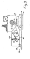
- Figures 1 and 2 there is shown a basic printing head mechanism of the type which can be incorporated into a franking machine or the like.
- the mechanism shown in Figures 1 and 2 and the subsequent five Figures is intended to illustrate the principle of operation and construction more clearly than is the case when the components are miniaturised and compacted more densely than in the mechanism shown.
- a final form of the apparatus illustrating the use of the same type of printing head in a parallel multi-head arrangement in a franking machine is shown in later Figures.
- a baseplate 10 serves as a support for two sideplates 12 and 14.
- a drive motor and gearbox assembly (not shown in detail) 16 is attached to and extends beyond the side wall 14 and serves to rotate a drive shaft 18 carrying a main print head operating cam 20 and a supplementary switch-actuating cam 22.
- a second shaft or rod 24 which is parallel to but spaced from and to the rear of the drive shaft 18.
- the printing head comprises a generally rectangular housing 26 which is pivotally attached at 28 on the one side and at a similar point (not visible in the drawings) on the other side of the housing 26 by means of stub- axles, to opposite side members 30 and 32 respectively of a yoke assembly generally designated 34.
- the latter is relatively freely floating in that it is secured to the baseplate 10 through a lost motion connection best seen in Figures 3 and 4.
- This comprises an upstanding pin 36 having an enlarged head 38 which holds captive the generally flat plate section of the yoke assembly 34.
- the latter includes an aperture (not shown) which is oversize relative to the diameter of the pin 36 so that the plate of the yoke assembly 34 can, in fact, tilt to one side or the other as well as in a generally up and down manner relative to the baseplate 10.
- the yoke assembly is held in place by means of a spring 40 located between a point of attachment at 42 in the middle of the plate of the yoke assembly 34 and attached to a fisher plate 44 which itself is threaded on the rod 24 extending between the two sidecheeks 12 and 14.
- the spring is selected so as to still be in tension when the side arms of the yoke assembly 30 and 32 engage the underside of the axle 18 which is the normal centralised position for the assembly under the action of the spring 40.
- the yoke assembly and therefore the printing head 26 can be moved in a downward direction for printing by rotation of the cam 20 to deflect the yoke 34 in the direction of the arrow 46 (see Figure 3).
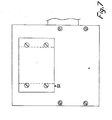
- the printing head includes a print face 48 containing characters which, if inked, will leave a suitable impression on an envelope or letter situated thereunder and aligned with and below the print face 48 is a platen 50 which is located in position by means of an underplate assembly 52 secured in position by means of four screws as can best be seen in Figure 7.
- Removal of the plate 52 gives uninterrupted access through an aperture (not shown) in the baseplate 10, to the print face 48 to facilitate checking, cleaning and replacing members of the print head assembly.
- the orientation of the print head 26 relative to the yoke arms 30 and 32 is maintained by means of at least one spring best seen in Figure 1.
- the spring includes two radial arms 52 and 54 and is looped at its centre around the protruding end of the stub-shaft 28 the outboard end of which is enlarged to prevent the spring loop from leaving the stub-shaft.
- the outboard ends of the radial arms 52 and 54 are secured on the one hand in an aperture 56 in the arm 30 and around a fixed stand-off 58 attached to the side of the print head housing 26.
- a similar spring (not shown) is provided on the other side of the housing 26 between it and the other arm 32 of the yoke assembly.
- the springs are selected so as to hold the print head housing 26 in the orientation shown in Figures 1, 2 and 3. Any attempt to tilt the head 26 in either direction denoted by the double-headed arrow 60 in Figure 3 will be resisted by the spring and the restoring force stored in the spring will tend to return the housing 26 to the orientation shown in Figures 1 to 3 as soon as any force tending to tilt the housing 26 relative to the yoke assembly is removed.
- Such a tilting force is, of course, exerted on the printing head assembly 26 in the event that an envelope or package is located below the print face 48 which is not of uniform thickness so that part of the print face is prevented from travelling in a downward direction by the same amount as another part of the print face.
- the head 26 can, relative to the baseplate 10 and therefore the platen 50, tilt not only in the direction of the double-headed arrow 60 but also from side to side as indicated by the curved arrows 62 and 64 in Figure 1.
- the printing head can therefore accommodate gross unevenness in a packet or envelope located therebelow.
- the printing head itself includes four endless belts of which one is shown at 66 in Figure 5, arranged in parallel-spaced arrangement within the head. Each follows a generally oval path and at its lower end passes around an inking reservoir and transfer pad not shown in detail but designated by reference numeral 68. To this end the material from which the endless loop.66 is formed is preferably porous at least to certain printing inks and forms a so-called retentive pad porous rubber printing medium.
- the belt or loop 66 is formed around its external surface with a series of upstanding segments such as 70 and 72 each of which can if desired carry a character in relief which when the material forming the belt or loop 66 is saturated with ink will form an impression of the character on a sheet of paper or the like located below the printing head in the position designated in dotted outline at 74.
- an opening is provided in the underside of the housing through which the lowermost of the segments 70, 72 etc can just protrude and in the illustration this is denoted by reference numeral 76.
- the belt passes around a driving pulley 78 which is either mounted directly onto one of the two head driveshafts 80 or 82 or is connected thereto through the intermediary of a uni-directional clutch (to be described).
- the driving wheel 78 can be thought of as comprising the shaft 80 or mounted thereon.
- Drive for the shaft 82 is provided by a first electric motor 84 the output shaft of which includes a toothed pinion 86 which meshes with a gearwheel 88 which in turn drives a second toothed pinion 90 for driving a larger diameter gearwheel 92 splined or otherwise secured to the shaft 82.
- the second motor and gear train for driving the other aligned but separate shaft 80 are not shown in Figures 1 and 2.
- the second motor is mounted back-to-back and may be in axial alignment with a first motor and a second gear train similar to that transmitting drive between the first motor and the shaft 82 is provided between the second motor (not shown) output shaft and the shaft 80.
- Each of the two shafts 80 and 82 extends into the housing 26 by a sufficient amount to almost touch the opposite end of the other shaft. However, the two shafts are entirely separate from-a rotational point of view.
- two of the four endless belts such as 70 are driven by one of the shafts 80 and another two are driven by the shaft 82.
- one of the endless belts in each pair is driven through a uni-directional clutch so that rotation of the shaft, for example, 80, in one direction will rotate both of the endless belts associated therewith but in the other direction will only drive the endless belt which is directly connected to the shaft or to a driving wheel itself non-rotatably secured on the shaft. Consequently, the two endless belts can be independently set so as to present selected characters such as 76 for printing by first of all rotating both of the endless belts in one direction until the first character associated with the clutched belt is in position and thereafter rotating the shaft in the opposite sense until the other character associated with the fixed wheel or belt has been moved into position.
- the other pair of endless belts can be set in a similar manner by rotation of the other motor, first in one direction and then the other.
- a separate uni-directional clutch may be provided for each drive to each of the belts so that both belts are completely independent and rotation of the shaft such as 80 in one direction will only cause one of the belts to be rotated whilst rotation in the other direction will cause the other belt to be rotated.
- toothed indexing wheel is associated with each individual belt.
- One such wheel is shown at 94 in Figure 5.
- the spacing between the teeth around the indexing wheel 94 is commensurate with the spacing between the upstanding segments such as 70, 72 around the endless belt 66 so that as the belt rotates so the indexing wheel must rotate by a corresponding number of segments.
- the indexing wheel 94 includes one or more electrical contacts (not shown) which, as the wheel 94 is indexed, make different combinations of connection between a plurality of conductors designated by reference numerals 96 and 98 by way of example only, carried by a conductor card 100 sandwiched between the index wheel 94 and the next index wheel along.
- reference numerals 96 and 98 by way of example only, carried by a conductor card 100 sandwiched between the index wheel 94 and the next index wheel along.
- an electrical signal can be derived indicative of the angular position of each of the four wheels 94 which therefore corresponds to the rotational position of the associated four endless belts 66 and therefore the four characters or groups of characters contained by the belts in the window in the underside of the printing head 26.
- the window and surrounding framework constitutes a print face 48 of Figure 3.
- a microswitch 104 is shown mounted close to the second cam 22 mounted on the shaft 18 with the microswitch actuating lever 106 acting as a cam follower.
- the cam is shaped and fitted to the shaft 18 so that the microswitch is operated once every revolution of the shaft 18 and is opened (or closed) as required at a position in which the lobe of the cam 20 is furthest from the plate of the yoke assembly 34.
- print head assembly shown in Figures 1 to 7 is eminently suitable for incorporation into a franking machine in which a plurality of such head assemblies are located side by side. Each different head assembly can then be dedicated to one particular task associated with the franking of mail and appropiate characters and printing devices are located in each such dedicated printing head assembly.
- FIG. 8 Arrangements such as this is shown in Figure 8 where four such printing heads are mounted at the end of four freely floating yoke or arm assemblies.
- the four printing heads are designated 108, 110, 112 and 114 and their respective support arms by the reference numerals 116, 118, 120 and 122.
- Actuating cams each corresponding to the cam 20 of Figure 1, are denoted by reference numerals 124, 126, 128 and 130 respectively.
- the lost motion free pivot points corresponding to the rear pin 36, 38 of Figure 3 are denoted by reference numerals 132, 134, 136 and 138 respectively.
- Springs corresponding to the spring 40 of Figure 3 are shown at 140, 142, 144 and 146.
- cams 124 to 130 are all mounted on a common shaft 148 and drive therefor is derived therefrom a motor and gearbox assembly (not shown) similar to the item 16 of Figure 1.
- Figure 9 illustrates the assembly of Figure 8 from the front as an elevation thereof in the direction of arrow 8.
- Print head 114 and 112 are each an ink-loaded porous rubber stamp having a printface 115 and 113 respectively containing characters or indicia which when urged into contact with a sheet of paper such as the outside of an envelope or packet will produce a pattern of information thereon.
- the print heads 110 and 108 respectively are constructed basically in the same way as the head shown in Figures 1 to 7 in that they comprise a series of endless belts (see Figure 11) of which one is designated 148 which have outwardly protruding segments containing characters for printing.
- Each of the belts can be indexed by appropriate rotation of one or the other of two drive shafts 150 and 152 which are themselves driven by toothed wheels 154 and 156 respectively themselves driven by worm gears 158 and 160 respectively on the outward shafts of two motors 162 and 164.
- the print head 110 is not motor-driven but is manually rotatable to adjust the print head characters and to this end two thumbwheels 166 and 168 are provided which have external serrations such as at 170 which engage appropriately toothed wheels 172 and 174 respectively.
- the toothed wheels just referred to serve to drive one or other of two short axles (not shown) to rotate one or other of the endless belts such as 176 and the endless belts are engaged by externally segmented indicator wheels of which one is designated at 178 each having external protrusions for engaging in the segments around the endless belt 176 so as to rotate therewith.
- the franking machine thus incorporates three different types of printing head within the overall assembly, two in which the printing plates are self-inked for life and two in which the endless belts are of a porous material and are replenished by ink from a reservoir such as at 184 (see Figure 10).
- Figure 11 shows the layout of the various parts making up the overall assembly at least insofar as the print head 108 is concerned.
- a yoke 116 and spring 140 operating cam 124 on shaft 148 and a stop shaft 186 (not shown in Figure 8) extends across and prevents upward movement of the yoke assembly 116 beyond a certain amount under the action of the spring 140.
- the encoder assembly 188 corresponds to the encoder cards 100 of Figures 1 to 7 embodiment and shown diagrammatically at 190 is one of the toothed wheels containing the electrical conductors which set up the contacts and circuits on the encoder boards and which rotates with rotation of the endless belt 148.
- a soft resiliently deformable pad 192 to absorb unevenness and thick contents of envelopes and packets.
- a stop 194 running along the length of the base 196 behind the platen area 192 serves as a guide as to where the envelope, packet or the like should be pushed before the printing head is lowered.
- Figures 12 and 13 illustrate a uni-directional clutch arrangement in which a shaft 196 has secured therein a diametrically extending dog 198 for engaging the inside of an annulus 200 which is formed as a circular internal ratchet.
- the dog 198 is slidable axially within the shaft 196. As the shaft 196 rotates in the direction of the arrow 202, drive is transmitted between the end 204 of the dog 198 and one of the teeth of the ratchet.
- Rotation of the shaft 196 in the opposite direction to arrow 202 causes the dog to ride up the inclined surface 206 and to enter the cutaway region 208 on the opposite side of the ratchet wheel so that there is no tendency for any rotational drive to occur between the shaft 196 and the internal ratchet wheel 200.
- Figure 14 shows more clearly than the views of Figures 1 - 7 the internal detail of the printing head 26.
- the shafts 80, 82 are formed with reduced axially parallel grooves at their inboard ends one of which is shown in the cross- sectioned half view of Figure 14, at 210.
- Rolling elements such as 212 are located in the grooves and support an annular member such as at 214 forming part of one of the driving wheels 78.
- the design of the grooves and rolling elements and shape of the interior of the annular member 214 is such that rotation of the shaft in one direction transmits drive to the driving wheel 78' whilst in the other direction, to the driving wheel 78".
- Endless bands containing printing characters are fitted arround the driving wheels 78 as previously described.
- indexing wheel 94 co-operates with driving wheel 78'.
- indexing wheels etc are shown in cross-section and the sliding electrical contact between the wheel and the conductive tracks on its associated card 100'.
- the indexing wheels 94', 94" etc are freely rotatable above their central supporting axle 220 whilst the cards are non-rotatable relative thereto.
- Figure 15 demonstrates how, after removing the coverplate 52 (shown in Figure 7) the underside of the printing head 26 can be clearly seen to permit the semi-permanent printing matter to be changed if required.
- This is shown as the rectangular cross-hatched region 222 defining the aperture 224 through which the variable printing characters protrude.
- the region 222 is held in place by six screws 226 and is replaceable by other surrounds as required by removing the screws 22 6 .
Landscapes
- Engineering & Computer Science (AREA)
- Computer Security & Cryptography (AREA)
- Physics & Mathematics (AREA)
- General Physics & Mathematics (AREA)
- Devices For Checking Fares Or Tickets At Control Points (AREA)
- Dot-Matrix Printers And Others (AREA)
Applications Claiming Priority (2)
| Application Number | Priority Date | Filing Date | Title |
|---|---|---|---|
| GB8332242 | 1983-12-02 | ||
| GB08332242A GB2150503B (en) | 1983-12-02 | 1983-12-02 | Franking machines |
Publications (3)
| Publication Number | Publication Date |
|---|---|
| EP0162169A2 true EP0162169A2 (de) | 1985-11-27 |
| EP0162169A3 EP0162169A3 (en) | 1987-08-19 |
| EP0162169B1 EP0162169B1 (de) | 1990-11-07 |
Family
ID=10552739
Family Applications (1)
| Application Number | Title | Priority Date | Filing Date |
|---|---|---|---|
| EP84308223A Expired EP0162169B1 (de) | 1983-12-02 | 1984-11-27 | Zum Drucken veränderlicher Daten geeignete Frankiermaschine |
Country Status (9)
| Country | Link |
|---|---|
| US (1) | US4665821A (de) |
| EP (1) | EP0162169B1 (de) |
| JP (1) | JPS60138696A (de) |
| CA (1) | CA1233067A (de) |
| DE (1) | DE3483580D1 (de) |
| GB (1) | GB2150503B (de) |
| PL (1) | PL250668A1 (de) |
| SG (1) | SG1388G (de) |
| YU (1) | YU203084A (de) |
Families Citing this family (4)
| Publication number | Priority date | Publication date | Assignee | Title |
|---|---|---|---|---|
| JPH01129242A (ja) * | 1987-11-13 | 1989-05-22 | Sharp Corp | 複写装置の原稿台往復機構 |
| US4923023A (en) * | 1987-12-17 | 1990-05-08 | Pitney Bowes Inc. | Modular mailing machine |
| US4893249A (en) * | 1987-12-17 | 1990-01-09 | Pitney Bowes, Inc. | Mailing machine |
| US4945831A (en) * | 1988-12-28 | 1990-08-07 | Pitney Bowes Inc. | Ink tray drive |
Family Cites Families (32)
| Publication number | Priority date | Publication date | Assignee | Title |
|---|---|---|---|---|
| DE166670C (de) * | ||||
| GB379124A (en) * | 1930-10-02 | 1932-08-25 | British Thomson Houston Co Ltd | Improvements in and relating to electro-hydraulic apparatus |
| GB720260A (en) * | 1951-05-08 | 1954-12-15 | Schwenk Zementwerke Ges Mit Be | Improved installation for manufacturing and applying mortar |
| GB727955A (en) * | 1953-07-29 | 1955-04-13 | Barford Agricultural Ltd | Improvements in or relating to free wheel units |
| DE1031601B (de) * | 1953-09-03 | 1958-06-04 | Kloeckner Humboldt Deutz Ag | Umkehrgetriebe |
| US2905294A (en) * | 1956-03-12 | 1959-09-22 | Clemson Bros Inc | Shuttle-pin clutch drive mechanism for lawn mowers |
| FR1199431A (fr) * | 1958-02-26 | 1959-12-14 | Perfectionnement des mécanismes d'inversion | |
| GB877161A (en) * | 1959-03-03 | 1961-09-13 | Seewer Gustave August | Improved dough-rolling machine |
| DE1174650B (de) * | 1962-08-10 | 1964-07-23 | Braun Ag | Trockenrasiergeraet mit umlaufendem Antrieb |
| DE1212028B (de) * | 1964-03-23 | 1966-03-10 | Pfaff Ag G M | Haushaltmuldenmangel |
| US3421437A (en) * | 1967-02-09 | 1969-01-14 | Takaji Funahashi | Revolving stamp |
| GB1179285A (en) * | 1967-08-17 | 1970-01-28 | Roneo Ltd | Improved Postal Franking Machine. |
| US3524406A (en) * | 1968-07-03 | 1970-08-18 | Norsta Eng | Marking apparatus having register means |
| US3667307A (en) * | 1968-07-19 | 1972-06-06 | Kienzle Apparate Gmbh | Stepping clutch device |
| US3504622A (en) * | 1968-09-13 | 1970-04-07 | Ralph Morrison | Print wheel setting and detenting means with electrical controls therefor |
| US3886862A (en) * | 1970-11-24 | 1975-06-03 | Monarch Marking Systems Inc | Selective printing apparatus |
| US3972281A (en) * | 1971-10-07 | 1976-08-03 | Norprint Limited | Adjustable print-out selection mechanisms |
| US3750565A (en) * | 1972-01-10 | 1973-08-07 | Pitney Bowes Inc | Print-setting apparatus |
| GB1431143A (en) * | 1973-05-28 | 1976-04-07 | Funahashi Takaji | Rubber hand stamps |
| US3902413A (en) * | 1973-09-27 | 1975-09-02 | Powell Shademarker Company | Shade marker |
| US3872789A (en) * | 1973-12-13 | 1975-03-25 | Electronic Memories & Magnetic | Printer with print wheels having coded perforations for selective positioning |
| US3921518A (en) * | 1974-01-16 | 1975-11-25 | Pitney Bowes Inc | High speed printer |
| AU8644275A (en) * | 1974-11-12 | 1977-05-12 | Bienholz S H | Print assembly |
| US3978457A (en) * | 1974-12-23 | 1976-08-31 | Pitney-Bowes, Inc. | Microcomputerized electronic postage meter system |
| US4246643A (en) * | 1978-02-13 | 1981-01-20 | Pitney Bowes Inc. | Low cost postage applicator |
| DD139154B1 (de) * | 1978-10-04 | 1981-02-25 | Walter Arpert | Doppeltwirkender freilauf |
| US4164191A (en) * | 1978-10-17 | 1979-08-14 | The Singer Company | Sewing machine motor actuated pneumatic pump for needle threading |
| US4259902A (en) * | 1979-10-30 | 1981-04-07 | Pitney Bowes Inc. | Electronic postage meter with power failure accounting protection system |
| JPS56144658U (de) * | 1980-04-02 | 1981-10-31 | ||
| US4367676A (en) * | 1981-05-22 | 1983-01-11 | Pitney Bowes, Inc. | Postage meter value selecting system |
| US4410287A (en) * | 1982-06-01 | 1983-10-18 | M. E. Cunningham Company | Single wheel billet marker |
| US4506344A (en) * | 1982-06-04 | 1985-03-19 | Pitney Bowes Inc. | Hand held electronic postage meter having secure postage meter doors |
-
1983
- 1983-12-02 GB GB08332242A patent/GB2150503B/en not_active Expired
-
1984
- 1984-11-27 EP EP84308223A patent/EP0162169B1/de not_active Expired
- 1984-11-27 DE DE8484308223T patent/DE3483580D1/de not_active Expired - Fee Related
- 1984-11-30 PL PL25066884A patent/PL250668A1/xx unknown
- 1984-11-30 US US06/676,851 patent/US4665821A/en not_active Expired - Lifetime
- 1984-12-01 JP JP59254931A patent/JPS60138696A/ja active Pending
- 1984-12-03 CA CA000469144A patent/CA1233067A/en not_active Expired
- 1984-12-03 YU YU02030/84A patent/YU203084A/xx unknown
-
1988
- 1988-01-07 SG SG13/88A patent/SG1388G/en unknown
Also Published As
| Publication number | Publication date |
|---|---|
| GB8332242D0 (en) | 1984-01-11 |
| GB2150503A (en) | 1985-07-03 |
| EP0162169A3 (en) | 1987-08-19 |
| GB2150503B (en) | 1987-05-28 |
| SG1388G (en) | 1988-06-17 |
| CA1233067A (en) | 1988-02-23 |
| YU203084A (en) | 1986-10-31 |
| EP0162169B1 (de) | 1990-11-07 |
| PL250668A1 (en) | 1985-08-13 |
| US4665821A (en) | 1987-05-19 |
| JPS60138696A (ja) | 1985-07-23 |
| DE3483580D1 (de) | 1990-12-13 |
Similar Documents
| Publication | Publication Date | Title |
|---|---|---|
| US4493252A (en) | Postage printing apparatus having a movable print head in a print drum | |
| US3504622A (en) | Print wheel setting and detenting means with electrical controls therefor | |
| US4676155A (en) | Drive unit | |
| EP0162169B1 (de) | Zum Drucken veränderlicher Daten geeignete Frankiermaschine | |
| EP0111314B1 (de) | Postbearbeitende Maschine und Briefumschlagauswurfsmechanismus für eine solche Maschine | |
| EP0145404B1 (de) | Aufhängung für einen Frankiermaschinendruckkopf | |
| GB2104004A (en) | Serial printing mechanism | |
| US4864924A (en) | Printwheel detent disengaging apparatus | |
| EP0144207A2 (de) | Frankiermaschine | |
| EP0239356B1 (de) | Frankiermaschine | |
| US4057015A (en) | Bar code printing system | |
| US4492159A (en) | Postage printing apparatus having a print head with a replaceable ribbon cartridge | |
| JPS6230476B2 (de) | ||
| US4852482A (en) | Automatic printwheel setting system | |
| US4492158A (en) | Postage printing apparatus having a movable print head and a hollow non-rotating support shaft | |
| US3921518A (en) | High speed printer | |
| CA1235510A (en) | Postal meter having thermal printer | |
| US3747517A (en) | Type wheel setting and locking means and print actuating means in selective printers | |
| US2307033A (en) | Printing mechanism | |
| CA1118486A (en) | Rotary electrical printer and method | |
| US4203122A (en) | Electrical stylus adjustment means and method for rotary electrical printer | |
| US4178599A (en) | Mounting structure for rotary electrical stylus device | |
| JPH0111490Y2 (de) | ||
| EP0442509A1 (de) | Miniaturdrucker | |
| CA2193756A1 (en) | Apparatus for printing an image indicative of value such as a postal indicia |
Legal Events
| Date | Code | Title | Description |
|---|---|---|---|
| PUAI | Public reference made under article 153(3) epc to a published international application that has entered the european phase |
Free format text: ORIGINAL CODE: 0009012 |
|
| AK | Designated contracting states |
Designated state(s): CH DE FR IT LI |
|
| PUAL | Search report despatched |
Free format text: ORIGINAL CODE: 0009013 |
|
| AK | Designated contracting states |
Kind code of ref document: A3 Designated state(s): CH DE FR IT LI |
|
| 17P | Request for examination filed |
Effective date: 19870901 |
|
| RAP1 | Party data changed (applicant data changed or rights of an application transferred) |
Owner name: FRANCOTYP-POSTALIA GMBH |
|
| 17Q | First examination report despatched |
Effective date: 19891123 |
|
| GRAA | (expected) grant |
Free format text: ORIGINAL CODE: 0009210 |
|
| AK | Designated contracting states |
Kind code of ref document: B1 Designated state(s): CH DE FR IT LI |
|
| PG25 | Lapsed in a contracting state [announced via postgrant information from national office to epo] |
Ref country code: IT Free format text: LAPSE BECAUSE OF FAILURE TO SUBMIT A TRANSLATION OF THE DESCRIPTION OR TO PAY THE FEE WITHIN THE PRESCRIBED TIME-LIMIT;WARNING: LAPSES OF ITALIAN PATENTS WITH EFFECTIVE DATE BEFORE 2007 MAY HAVE OCCURRED AT ANY TIME BEFORE 2007. THE CORRECT EFFECTIVE DATE MAY BE DIFFERENT FROM THE ONE RECORDED. Effective date: 19901107 |
|
| REF | Corresponds to: |
Ref document number: 3483580 Country of ref document: DE Date of ref document: 19901213 |
|
| ET | Fr: translation filed | ||
| PLBE | No opposition filed within time limit |
Free format text: ORIGINAL CODE: 0009261 |
|
| STAA | Information on the status of an ep patent application or granted ep patent |
Free format text: STATUS: NO OPPOSITION FILED WITHIN TIME LIMIT |
|
| 26N | No opposition filed | ||
| PGFP | Annual fee paid to national office [announced via postgrant information from national office to epo] |
Ref country code: DE Payment date: 20020920 Year of fee payment: 19 |
|
| PGFP | Annual fee paid to national office [announced via postgrant information from national office to epo] |
Ref country code: FR Payment date: 20020926 Year of fee payment: 19 |
|
| PGFP | Annual fee paid to national office [announced via postgrant information from national office to epo] |
Ref country code: CH Payment date: 20030227 Year of fee payment: 19 |
|
| PG25 | Lapsed in a contracting state [announced via postgrant information from national office to epo] |
Ref country code: LI Free format text: LAPSE BECAUSE OF NON-PAYMENT OF DUE FEES Effective date: 20031130 Ref country code: CH Free format text: LAPSE BECAUSE OF NON-PAYMENT OF DUE FEES Effective date: 20031130 |
|
| PG25 | Lapsed in a contracting state [announced via postgrant information from national office to epo] |
Ref country code: DE Free format text: LAPSE BECAUSE OF NON-PAYMENT OF DUE FEES Effective date: 20040602 |
|
| REG | Reference to a national code |
Ref country code: CH Ref legal event code: PL |
|
| PG25 | Lapsed in a contracting state [announced via postgrant information from national office to epo] |
Ref country code: FR Free format text: LAPSE BECAUSE OF NON-PAYMENT OF DUE FEES Effective date: 20040730 |
|
| REG | Reference to a national code |
Ref country code: FR Ref legal event code: ST |