EP0162393B2 - Embrayage ou frein à friction avec un élément de friction composé d'un support en tôle et d'une déposition d'une garniture de friction en matériau fritté - Google Patents
Embrayage ou frein à friction avec un élément de friction composé d'un support en tôle et d'une déposition d'une garniture de friction en matériau fritté Download PDFInfo
- Publication number
- EP0162393B2 EP0162393B2 EP85105822A EP85105822A EP0162393B2 EP 0162393 B2 EP0162393 B2 EP 0162393B2 EP 85105822 A EP85105822 A EP 85105822A EP 85105822 A EP85105822 A EP 85105822A EP 0162393 B2 EP0162393 B2 EP 0162393B2
- Authority
- EP
- European Patent Office
- Prior art keywords
- friction
- synchronizing
- base body
- synchronizing ring
- ring
- Prior art date
- Legal status (The legal status is an assumption and is not a legal conclusion. Google has not performed a legal analysis and makes no representation as to the accuracy of the status listed.)
- Expired - Lifetime
Links
- 239000002184 metal Substances 0.000 title claims description 3
- 229910052751 metal Inorganic materials 0.000 title claims description 3
- 239000002783 friction material Substances 0.000 title description 3
- 230000008021 deposition Effects 0.000 title 1
- 229910000831 Steel Inorganic materials 0.000 claims description 15
- 239000010959 steel Substances 0.000 claims description 15
- 239000000463 material Substances 0.000 claims description 14
- 238000004519 manufacturing process Methods 0.000 claims description 10
- 238000000034 method Methods 0.000 claims description 9
- 239000011248 coating agent Substances 0.000 claims description 7
- 238000000576 coating method Methods 0.000 claims description 7
- 238000006073 displacement reaction Methods 0.000 claims description 7
- 230000008569 process Effects 0.000 claims description 7
- 238000003466 welding Methods 0.000 claims description 4
- 230000003746 surface roughness Effects 0.000 claims description 3
- 239000000843 powder Substances 0.000 claims description 2
- 238000003825 pressing Methods 0.000 claims description 2
- 238000002788 crimping Methods 0.000 claims 1
- 238000004049 embossing Methods 0.000 claims 1
- 238000005096 rolling process Methods 0.000 claims 1
- 238000005245 sintering Methods 0.000 claims 1
- 238000012360 testing method Methods 0.000 description 13
- 239000003921 oil Substances 0.000 description 12
- 238000013461 design Methods 0.000 description 11
- 229910001369 Brass Inorganic materials 0.000 description 8
- 239000010951 brass Substances 0.000 description 8
- 239000012208 gear oil Substances 0.000 description 5
- 230000005540 biological transmission Effects 0.000 description 4
- 229910000906 Bronze Inorganic materials 0.000 description 3
- 241000446313 Lamella Species 0.000 description 3
- ZOKXTWBITQBERF-UHFFFAOYSA-N Molybdenum Chemical compound [Mo] ZOKXTWBITQBERF-UHFFFAOYSA-N 0.000 description 3
- 230000008901 benefit Effects 0.000 description 3
- 230000015572 biosynthetic process Effects 0.000 description 3
- 239000010974 bronze Substances 0.000 description 3
- KUNSUQLRTQLHQQ-UHFFFAOYSA-N copper tin Chemical compound [Cu].[Sn] KUNSUQLRTQLHQQ-UHFFFAOYSA-N 0.000 description 3
- 238000005461 lubrication Methods 0.000 description 3
- 229910052750 molybdenum Inorganic materials 0.000 description 3
- 239000011733 molybdenum Substances 0.000 description 3
- 230000009467 reduction Effects 0.000 description 3
- 208000002991 Ring chromosome 4 syndrome Diseases 0.000 description 2
- 229910010293 ceramic material Inorganic materials 0.000 description 2
- 230000008878 coupling Effects 0.000 description 2
- 238000010168 coupling process Methods 0.000 description 2
- 238000005859 coupling reaction Methods 0.000 description 2
- 238000005336 cracking Methods 0.000 description 2
- 230000000694 effects Effects 0.000 description 2
- 238000002474 experimental method Methods 0.000 description 2
- 238000010438 heat treatment Methods 0.000 description 2
- 238000004544 sputter deposition Methods 0.000 description 2
- 230000003068 static effect Effects 0.000 description 2
- OKTJSMMVPCPJKN-UHFFFAOYSA-N Carbon Chemical compound [C] OKTJSMMVPCPJKN-UHFFFAOYSA-N 0.000 description 1
- 206010010219 Compulsions Diseases 0.000 description 1
- 229910002535 CuZn Inorganic materials 0.000 description 1
- 229910000760 Hardened steel Inorganic materials 0.000 description 1
- 208000035187 Ring chromosome 14 syndrome Diseases 0.000 description 1
- 208000032825 Ring chromosome 2 syndrome Diseases 0.000 description 1
- RTAQQCXQSZGOHL-UHFFFAOYSA-N Titanium Chemical compound [Ti] RTAQQCXQSZGOHL-UHFFFAOYSA-N 0.000 description 1
- 238000004873 anchoring Methods 0.000 description 1
- 229910052799 carbon Inorganic materials 0.000 description 1
- 230000008859 change Effects 0.000 description 1
- 230000007423 decrease Effects 0.000 description 1
- 238000011161 development Methods 0.000 description 1
- 230000018109 developmental process Effects 0.000 description 1
- 238000007667 floating Methods 0.000 description 1
- 238000000227 grinding Methods 0.000 description 1
- 230000017525 heat dissipation Effects 0.000 description 1
- 238000010348 incorporation Methods 0.000 description 1
- 229910010272 inorganic material Inorganic materials 0.000 description 1
- 239000011147 inorganic material Substances 0.000 description 1
- 238000011835 investigation Methods 0.000 description 1
- 239000010687 lubricating oil Substances 0.000 description 1
- 238000003754 machining Methods 0.000 description 1
- 230000007257 malfunction Effects 0.000 description 1
- 238000005259 measurement Methods 0.000 description 1
- 239000002480 mineral oil Substances 0.000 description 1
- 235000010446 mineral oil Nutrition 0.000 description 1
- 229940020991 molybdenum injection Drugs 0.000 description 1
- 150000004767 nitrides Chemical class 0.000 description 1
- 230000002028 premature Effects 0.000 description 1
- 230000000717 retained effect Effects 0.000 description 1
- 229910021332 silicide Inorganic materials 0.000 description 1
- FVBUAEGBCNSCDD-UHFFFAOYSA-N silicide(4-) Chemical compound [Si-4] FVBUAEGBCNSCDD-UHFFFAOYSA-N 0.000 description 1
- 239000000243 solution Substances 0.000 description 1
- 239000007921 spray Substances 0.000 description 1
- 230000001360 synchronised effect Effects 0.000 description 1
- 229920003002 synthetic resin Polymers 0.000 description 1
- 239000000057 synthetic resin Substances 0.000 description 1
- 230000007704 transition Effects 0.000 description 1
Images


Classifications
-
- F—MECHANICAL ENGINEERING; LIGHTING; HEATING; WEAPONS; BLASTING
- F16—ENGINEERING ELEMENTS AND UNITS; GENERAL MEASURES FOR PRODUCING AND MAINTAINING EFFECTIVE FUNCTIONING OF MACHINES OR INSTALLATIONS; THERMAL INSULATION IN GENERAL
- F16D—COUPLINGS FOR TRANSMITTING ROTATION; CLUTCHES; BRAKES
- F16D23/00—Details of mechanically-actuated clutches not specific for one distinct type
- F16D23/02—Arrangements for synchronisation, also for power-operated clutches
- F16D23/025—Synchro rings
-
- F—MECHANICAL ENGINEERING; LIGHTING; HEATING; WEAPONS; BLASTING
- F16—ENGINEERING ELEMENTS AND UNITS; GENERAL MEASURES FOR PRODUCING AND MAINTAINING EFFECTIVE FUNCTIONING OF MACHINES OR INSTALLATIONS; THERMAL INSULATION IN GENERAL
- F16D—COUPLINGS FOR TRANSMITTING ROTATION; CLUTCHES; BRAKES
- F16D23/00—Details of mechanically-actuated clutches not specific for one distinct type
- F16D23/02—Arrangements for synchronisation, also for power-operated clutches
- F16D23/04—Arrangements for synchronisation, also for power-operated clutches with an additional friction clutch
-
- F—MECHANICAL ENGINEERING; LIGHTING; HEATING; WEAPONS; BLASTING
- F16—ENGINEERING ELEMENTS AND UNITS; GENERAL MEASURES FOR PRODUCING AND MAINTAINING EFFECTIVE FUNCTIONING OF MACHINES OR INSTALLATIONS; THERMAL INSULATION IN GENERAL
- F16D—COUPLINGS FOR TRANSMITTING ROTATION; CLUTCHES; BRAKES
- F16D69/00—Friction linings; Attachment thereof; Selection of coacting friction substances or surfaces
- F16D69/02—Composition of linings ; Methods of manufacturing
- F16D69/027—Compositions based on metals or inorganic oxides
-
- F—MECHANICAL ENGINEERING; LIGHTING; HEATING; WEAPONS; BLASTING
- F16—ENGINEERING ELEMENTS AND UNITS; GENERAL MEASURES FOR PRODUCING AND MAINTAINING EFFECTIVE FUNCTIONING OF MACHINES OR INSTALLATIONS; THERMAL INSULATION IN GENERAL
- F16D—COUPLINGS FOR TRANSMITTING ROTATION; CLUTCHES; BRAKES
- F16D2300/00—Special features for couplings or clutches
- F16D2300/10—Surface characteristics; Details related to material surfaces
-
- Y—GENERAL TAGGING OF NEW TECHNOLOGICAL DEVELOPMENTS; GENERAL TAGGING OF CROSS-SECTIONAL TECHNOLOGIES SPANNING OVER SEVERAL SECTIONS OF THE IPC; TECHNICAL SUBJECTS COVERED BY FORMER USPC CROSS-REFERENCE ART COLLECTIONS [XRACs] AND DIGESTS
- Y10—TECHNICAL SUBJECTS COVERED BY FORMER USPC
- Y10T—TECHNICAL SUBJECTS COVERED BY FORMER US CLASSIFICATION
- Y10T29/00—Metal working
- Y10T29/49—Method of mechanical manufacture
- Y10T29/4998—Combined manufacture including applying or shaping of fluent material
- Y10T29/49982—Coating
Definitions
- the invention relates to a synchronizing ring and / or synchronizing counter cone of the type defined in the preamble of claim 1.
- the large area of friction clutches and brakes can be divided into types, types of friction pairing and lubrication as well as type of operation and shifting force.
- a distinction must be made between jaw, cone and disc clutches.
- a distinction is made between dry-running and lubricated friction surfaces, with and without a special friction lining.
- the type of operation and shifting force are particularly important for the friction linings, which are mainly lubricated with oil. During the switching process, the oil must be pressed out between the friction surfaces in order to achieve frictional engagement with a high coefficient of friction.
- pneumatic or hydraulic boosters are available for this purpose, high switching forces can be easily generated, which displace the oil between the pairs of friction surfaces.
- the switching or braking properties of friction clutches or brakes are determined in particular by the friction characteristics of the friction surface pairings and by the size of the friction surface that is actually effective.
- the actually effective friction surface is the proportion of the geometric friction surface that actually engages with the partner surface when engaged. Friction surfaces have a more or less strong surface formation, which means a reduction in the actually effective friction surface.
- lubricated friction surfaces have drainage grooves and grooves in the friction surfaces for removing the oil during the production of the frictional connection between the surfaces of the pair of friction surfaces. Such grooves have so far been indispensable, at least in the case of hand-operated friction clutches and brakes, and mean a reduction in the actually effective friction surface by 30% to 80% of the geometric friction surface.
- the surface shape of the two friction partners can differ from one another due to manufacturing-related tolerances or due to deformations under the friction pressure, so that for this reason the effective friction surface is often significantly reduced compared to the geometric friction surface.
- Friction surfaces are subject to high shear and temperature stresses and friction wear that increases with temperature. In order to keep this low, the actually effective and consequently the geometric friction surfaces should be as large as possible. The high demands on their wear resistance require friction surfaces made of high quality, expensive materials. For reasons of material and thus cost savings, however, the friction surfaces are designed to be as small as is justifiable. In the case of highly stressed friction clutches and brakes, molded parts made of base materials such as steel, brass and various bronzes can be found today, to which specific friction linings may be applied using a wide variety of processes.
- DE-A-3 122 522 describes a synchronizing device for positive-locking clutches, in which the synchronizing ring and / or the synchronizing ring are made of metal and the friction lining is made of ceramic material, the ceramic material as a load-bearing element having shape, friction and / or is integrally connected to the synchronizing and / or synchronizing ring or is applied by sputtering.
- the friction lining is based on oxide and / or silicide and / or boride and / or carbide and / or nitride and / or titanate.
- Synchronizer rings and synchronizer rings according to this prior publication have a number of the difficulties discussed above that remain unchanged.
- the materials for the friction lining according to DE-A-3 122 522 are particularly expensive, especially when they are designed as self-supporting shaped bodies. Nevertheless, the introduction of drainage grooves cannot be dispensed with. The result is a reduction in the actually effective friction surface or the compulsion to dimension the geometric friction surface even larger and therefore more expensive.
- a synchronizing ring DE-A-2 744 994
- the friction body is made of paper. It has a number of organic friction materials soaked in synthetic resin.
- Such friction linings are relatively inexpensive to produce, but due to their low strength they allow only a small amount of friction, so that relatively large geometrical friction surfaces must be available in the synchronizing rings, which means large and expensive ring designs. This in turn is often not possible to the extent necessary due to the limited available space. Large friction surfaces only slowly displace the oil film during the production of the frictional connection, which results in a long synchronization time. Furthermore, the friction characteristic changes due to the incorporation of carbon, which is produced by cracking the oil due to high friction temperatures, which leads to a failure of the synchronization device.
- DE-U-7 342 680 describes a synchronizing ring made of sintered steel, on which a thin molybdenum layer is applied in the area of the friction surface.
- Molybdenum injection material is an expensive material. As a rule, it must be densified on the ring and, as a rule, brought to the required, very closely tolerated surface dimensions by grinding. In a further work process, drainage grooves have to be introduced, so that such synchronizing rings are very expensive.
- the applied layer has a relatively large surface roughness, so that the effective friction surface is comparatively small. In particular, this often results in strong local heating in the friction surface in practice, which results in the synchronizer ring and the synchronizing ring seizing and the molybdenum layer becoming detached. This also results in considerable malfunctions of the clutch.
- multi-plate clutches have gained particular importance in the field of friction clutches or brakes with flat, lubricated and also non-lubricated friction surfaces, in particular clutch disks provided on both sides with a friction lining and arranged as a whole disk set next to one another. With these couplings large moments can be transmitted without the surface pressure or the specific heat flow per coupling surface unit becoming too great.
- those consisting of a friction body with a sintered friction lining have acquired particular technical importance.
- Friction bodies with scattered sintered friction linings are produced on a large scale as flat, disc-shaped friction bodies or lamellas and are therefore inexpensive.
- a powder consisting of various components is applied precisely metered to a flat carrier plate, sintered, pressed and compacted in a series of process stages, pressure sintered, brushed and, as a rule, compacted exactly to the desired covering thickness in a final process step. If necessary, grooves and grooves can already be pressed into the surface of the covering during the manufacturing process, without notching effects and the risk of cracking, as is frequently observed with subsequent application by means of machining processes.
- DE-B-1 251 104 describes a friction body which consists of a base plate and two layers attached and sintered thereon, a bottom layer and an outer layer.
- protrusions are produced in the underlay sheet before the coating, which then follow when bringing the friction body together with a carrier plate, extend into corresponding openings in the carrier plate and thus serve as anchoring against rotation of the two parts relative to one another.
- the invention is therefore based on the object to design the synchronizing device of the type mentioned and to show a method for their production that they can be produced inexpensively, allow high utilization of the geometrical friction surface, have a comparatively long service life, large short-term overloadability and only low, premature Failure frequency and yet do not have the disadvantages of known designs described above, or only have them to a much lesser extent.
- the friction body is formed from a carrier plate with scattered sintered friction lining which is sprinkled on, sintered on and compacted by pressing one or more times.
- the friction body does not have a friction surface used collar
- the friction body is soldered or welded to a base body in the region of the collar (see Figure 1).
- This configuration enables a technically particularly simple welded connection between the base body and the friction body by applying a closed weld seam in the area of the annular collar.
- a deep-drawn steel sheet is preferably used as the carrier sheet for the scattered sintered friction lining.
- the friction body which can only be manufactured as a flat lamella, is brought into the shape desired for the friction surface by deep drawing.
- the friction surface of the friction body has a surface structure which makes any additional formation of drainage grooves for oil displacement superfluous for a large number of applications; this applies in particular when using lubricating oils with a viscosity of up to 2500 mm2 / sec. H. for common gear oils from a temperature of approx. -10 ° C. This advantageous property is retained even after the originally sintered friction lining has been formed by deep drawing into the desired, non-planar shape.
- This configuration allows larger manufacturing tolerances and thus an inexpensive design. Compared to designs that comply with the customary narrow tolerances, it nevertheless ensures a comparatively good ratio of the geometric and actually effective friction surface.
- the section in FIG. 1 shows, in simplified form, a synchronizing ring -4- and an associated synchronizing ring -14-.
- the conical friction surface of the synchronizing ring -2- and the friction surface -12- of the synchronizing ring are at a distance from one another. You are not in a tight fit.
- the friction body -1- is attached in the form of the sintered friction lining; it has a collar -3- not used as a friction surface and is integrally connected to the base body via a ring weld seam -5-.
- Figure 2 shows a section of the oblique view of a synchronizing ring -4-.
- the friction body is applied to the conical friction surface -9- of the same.
- this friction body has been pre-folded in such a way that it lies along individual, strip-shaped surface sections -6- on the base body and is integrally connected to the base body in this area, for example by spot welding. Because of the fold, the rest of the friction surface -7- does not rest on the base body, but has an approximately constant, gap-shaped distance -8- from the base body.
- the surface part of the friction body that does not rest on the base body can fully fit the corresponding friction surface of the synchronizing ring due to its elasticity.
- the dimensional inaccuracies of the conical friction surfaces thus have no influence on the contact pattern, and changes in shape of the friction surface due to pressure and temperature stress can be compensated for without any effect on the actually effective friction surface. Furthermore, this configuration reduces the risk of friction vibrations occurring.
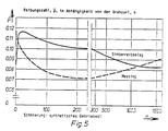
- the coefficient of friction ⁇ as a function of the speed n was determined in a practical test arrangement, firstly for a conical surface covered with a friction body according to the present invention and secondly for a friction body with the same size Geometric friction surface made of brass (CuZn 40 Al2) determined.
- ⁇ means an average of the coefficient of friction from four tests with the contact forces 50, 100, 200 and 400 N.
- the speed n is measured in revolutions per minute. 1000 rpm corresponds to a sliding speed of 2.9 m / s.
- the width of the conical surface was 10 mm. While the friction body according to the invention had no grooves for oil displacement, the brass ring (synchronizer ring produced as standard) had axial grooves and a pointed thread for oil displacement.
- a friction cone made of 16MnCr5E steel with a surface roughness R a / R z 0.15 / 1.4 ⁇ m was available for the tests.
- FIGS. 3-5 show the three test series being distinguished by the use of different gear oils.
- FIG. 3 shows the measured values using a hypoid gear oil, in FIG. 4 a paraffinic mineral oil with 5% anglamol and in FIG. 5 a synthetic gear oil.
- the measured values shown in the figures were measured at a constant speed during a 1-2 second load.
- the sliding friction is significantly higher for a friction body according to the present invention than for the example of a known embodiment.
- a certain frictional torque can thus be generated to a previously unpredictable extent with a significantly smaller contact pressure than in known designs.
- a friction clutch for example a synchronizing ring, enables shorter synchronization times and thus faster gear changes with less friction work.
- a second major advantage of the solution according to the invention compared to known designs is the significantly lower static friction of the former, which means a wear-reducing transition which increases the shifting comfort from relative movement to synchronism of the components of a friction clutch and thus permits very smooth switching.
- Synchronizing rings (diameter 108 mm) with a conical friction surface of 10 mm width were tested. The following were tested in comparison: a synchronizing ring with a friction body according to the present invention, a brass ring and a synchronizing ring made of sintered steel with a sprayed on and compressed molybdenum friction lining.
- Friction bodies with scattered sintered friction linings, applied to synchronizing rings, are corresponding rings made of brass with respect to their durability and are slightly superior to sintered steel rings with Mo-coating, but they are above all much better in the manufacturing price.
- the brass ring of the abovementioned friction surface dimensions shows a material loss of 2-8 mg in the above-mentioned practical test arrangement; the sintered steel ring with Mo coating has a material loss of 1 - 4 mg, while the material loss of the scattered sintered friction coating examined for comparison cannot be measured.
- the synchronization ring according to the present application consisted of a base body, in particular sintered steel, onto which a commercially available HS 43 t scatter sintered friction body was applied by means of spot welding through the friction surface.
- the friction material of the friction lining consists in particular of metallic and non-metallic inorganic materials.
Landscapes
- Engineering & Computer Science (AREA)
- General Engineering & Computer Science (AREA)
- Mechanical Engineering (AREA)
- Chemical & Material Sciences (AREA)
- Inorganic Chemistry (AREA)
- Mechanical Operated Clutches (AREA)
- Braking Arrangements (AREA)
Claims (9)
- Anneau de synchronisation et anneau synchrone pour agencements de commande manoeuvrés manuellement de vèhicules automobiles avec surfaces de frottement lubrifiées non planes et/ou géométriquement non développables, un corps de friction (1) préfabriqué séparément en conditione plane étant utilisé pour la surface de frottement et étant appliqué, avec faconnage, sur un corps de base en matière métallique auquel il est lié par conjugaison de matière, de formes ou par force,
caractérisé
par le fait que le corps de friction (1) est formé par une tôle porteuse avec une garniture de friction rapportée-frittée obtenue par application de matière puis frittage et ensuite compactage par compression en une ou plusieurs fois. - Anneau de synchronisation et anneau synchrone selon la revendication 1, caractérisé par le fait que le corps de friction (1) est en une ou plusieurs parties et est rapporté sur le corps de base auquel il est lié, au moins dans des régions partielles de celui-ci, par conjugaison de formes, par liaison de frottement et/ou par liaison par matière.
- Anneau de synchronisation et anneau synchrone selon la revendication 2, caractérisé par le fait que le corps de friction (1) présente un collet (3) non utilisé en tant que surface de frottement (2) et est lié par brasage ou soudage au corps de base, dans la région de ce collet.
- Anneau de synchronisation et anneau synchrone selon la revendication 2 ou 3, caractérisé par le fait que le corps de friction est lié au corps de base de l'embrayage à friction ou du frein, dans la région de la surface de frottement, par soudage au travers du corps de friction.
- Anneau de synchronisation et anneau synchrone selon l'une des revendications 2 à 4, caractérisé par le fait que le corps de friction (1) est doté de plis de formage préalables et est ainsi rapporté sur le corps de base.
- Anneau de synchronisation et anneau synchrone selon l'une des revendications 2 à 5, caractérisé par le fait qu'il est un anneau de synchronisation (4) avec un corps de base en acier fritté.
- Anneau de synchronisation et anneau synchrone selon l'une des revendications 1 à 6, caractérisé par le fait que la tôle-support est une tôle d'acier apte à l'emboutissage.
- Anneau de synchronisation et anneau synchrone selon l'une des revendications 1 à 7, caractérisé par le fait que la surface de frottement présente une rugosité de surface à structure régulière, convenant pour le déplacement d'huile.
- Procédé de réalisation d'un embrayage à anneau de synchronisation et anneau synchrone selon l'une des revendications 2 à 8, caractérisé par le fait que le corps de friction (1) mis, au moins approximativement, à la forme des surfaces de frottement, est rapporté sur le corps de base auquel il est lié par frottement et, au noins dans des surfaces partielles, par conjugaison de formes, par laminage, y compris par moletage.
Applications Claiming Priority (2)
| Application Number | Priority Date | Filing Date | Title |
|---|---|---|---|
| DE3417813A DE3417813C1 (de) | 1984-05-14 | 1984-05-14 | Verwendung von Streusinter-Reibbelaegen in Reibkupplungen oder -bremsen |
| DE3417813 | 1984-05-14 |
Publications (3)
| Publication Number | Publication Date |
|---|---|
| EP0162393A1 EP0162393A1 (fr) | 1985-11-27 |
| EP0162393B1 EP0162393B1 (fr) | 1988-09-21 |
| EP0162393B2 true EP0162393B2 (fr) | 1994-04-20 |
Family
ID=6235773
Family Applications (1)
| Application Number | Title | Priority Date | Filing Date |
|---|---|---|---|
| EP85105822A Expired - Lifetime EP0162393B2 (fr) | 1984-05-14 | 1985-05-11 | Embrayage ou frein à friction avec un élément de friction composé d'un support en tôle et d'une déposition d'une garniture de friction en matériau fritté |
Country Status (4)
| Country | Link |
|---|---|
| US (1) | US5143192A (fr) |
| EP (1) | EP0162393B2 (fr) |
| JP (1) | JPS6117723A (fr) |
| DE (1) | DE3417813C1 (fr) |
Cited By (1)
| Publication number | Priority date | Publication date | Assignee | Title |
|---|---|---|---|---|
| AT409098B (de) * | 1989-03-30 | 2002-05-27 | Miba Sintermetall Ag | Verfahren zum herstellen eines reibringes für kupplungen oder bremsen mit einem gesinterten reibbelag |
Families Citing this family (64)
| Publication number | Priority date | Publication date | Assignee | Title |
|---|---|---|---|---|
| AT385826B (de) * | 1986-03-21 | 1988-05-25 | Hoerbiger & Co | Reibring fuer kupplungen oder bremsen, verfahren und vorrichtung zum herstellen des reibringes |
| DE3609879A1 (de) * | 1986-03-24 | 1987-10-08 | Hoerbiger & Co | Reibring fuer kupplungen oder bremsen, verfahren und vorrichtung zum herstellen des reibringes |
| WO1987006314A1 (fr) * | 1986-04-16 | 1987-10-22 | Zahnradfabrik Friedrichshafen Ag | Bague de synchronisation |
| JPS63219923A (ja) * | 1986-11-03 | 1988-09-13 | エーリヒ・エル・ミュラー | 摩擦結合部材、特に自動車のレンジ・トランスミッション同期化部材を製造する方法および装置 |
| DE3637386C1 (de) * | 1986-11-03 | 1987-09-24 | Neuenstein Zahnradwerk | Verfahren und Vorrichtung zum Herstellen von Synchronisierungskoerpern in Stufengetrieben von Kraftfahrzeugen |
| DE3724000A1 (de) * | 1986-11-03 | 1988-05-05 | Neuenstein Zahnradwerk | Verfahren und vorrichtung zum herstellen von reibschluessigen elementen, insbesondere von synchronisierungskoerpern in stufengetrieben von kraftfahrzeugen |
| DE3728643A1 (de) * | 1986-11-14 | 1988-05-26 | Neuenstein Zahnradwerk | Verfahren zum herstellen von reibschluessigen elementen insbesondere von synchronisierungskoerpern in stufengetrieben von kraftfahrzeugen und reibschluessiges element |
| EP0267561A1 (fr) * | 1986-11-14 | 1988-05-18 | ZWN ZAHNRADWERK NEUENSTEIN GMBH & CO. | Procédé de fabrication de corps de synchronisation pour transmissions de véhicule |
| ATA315486A (de) * | 1986-11-26 | 1987-12-15 | Miba Sintermetall Ag | Verfahren zum herstellen eines reibringes mit einer konischen oder zylindrischen reibflaeche |
| DE3705657A1 (de) * | 1987-02-21 | 1988-09-01 | Neuenstein Zahnradwerk | Reibring mit einer konischen oder zylindrischen reibflaeche |
| DE3744898C2 (en) * | 1987-02-21 | 1990-11-29 | Zwn Zahnradwerk Neuenstein Gmbh & Co, 7113 Neuenstein, De | Mfg. synchromesh ring with friction face |
| DE3705658A1 (de) * | 1987-02-21 | 1988-09-08 | Neuenstein Zahnradwerk | Verfahren zum herstellen eines reibringes mit einer konischen oder zylindrischen reibflaeche |
| DE3705660A1 (de) * | 1987-02-21 | 1988-09-08 | Neuenstein Zahnradwerk | Verfahren zum herstellen eines reibringes mit einer konischen oder zylindrischen reibflaeche |
| AT387266B (de) * | 1987-05-20 | 1988-12-27 | Enfo Grundlagen Forschungs Ag | Reib- bzw. gleitkoerper, sowie verfahren und vorrichtung zu dessen herstellung |
| DE3806828A1 (de) * | 1988-03-03 | 1989-09-14 | Sinterstahl Gmbh | Reibkupplung fuer kfz-getriebe und verfahren zu deren herstellung |
| DE4017142A1 (de) * | 1990-05-28 | 1991-12-05 | Kloeckner Humboldt Deutz Ag | Synchronisiereinrichtung fuer zahnradwechselgetriebe |
| AT410359B (de) * | 1992-12-14 | 2003-04-25 | Miba Sintermetall Ag | Verfahren zum herstellen eines reibringes für kupplungen oder bremsen |
| AT409411B (de) * | 1992-12-14 | 2002-08-26 | Miba Sintermetall Ag | Verfahren zum herstellen eines reibringes für kupplungen oder bremsen |
| AT401255B (de) * | 1994-02-25 | 1996-07-25 | Hoerbiger & Co | Reibbelag |
| US5691283A (en) * | 1994-03-01 | 1997-11-25 | Ethyl Petroleum Additives Limited | Use of transmission and gear oil lubricants having enhanced friction properties |
| US5526914A (en) * | 1994-04-12 | 1996-06-18 | Lanxide Technology Company, Lp | Brake rotors, clutch plates and like parts and methods for making the same |
| ES2119642B1 (es) * | 1994-07-12 | 1999-04-01 | Fichtel & Sachs Ag | Embrague de friccion |
| US5582281A (en) * | 1994-07-19 | 1996-12-10 | Chuetsu Metal Works Co., Ltd. | Method of connecting a sliding member to a synchronizer ring |
| US5615758A (en) * | 1994-09-30 | 1997-04-01 | Nels; Terry E. | Fabric arrangement and method for controlling fluid flow |
| US6065579A (en) * | 1994-09-30 | 2000-05-23 | Select Powertrain Technologies Corp. | Synchronizer blocker rings used in manual transmissions |
| DE4445898A1 (de) * | 1994-12-22 | 1996-06-27 | Schaeffler Waelzlager Kg | Reibpaarung für eine Synchronisiereinrichtung in Zahnräderwechselgetrieben |
| AT405256B (de) * | 1995-02-16 | 1999-06-25 | Miba Sintermetall Ag | Verfahren zum herstellen einer schiebemuffe für die synchronisiereinrichtung eines zahnradwechselgetriebes |
| DE19529104A1 (de) * | 1995-08-08 | 1997-02-13 | Claas Ohg | Antriebssystem für ein Raupenfahrzeug |
| DE19548124C2 (de) * | 1995-12-21 | 2002-08-29 | Euroflamm Gmbh | Reibkörper und Verfahren zum Herstellen eines solchen |
| JPH09202905A (ja) * | 1996-01-24 | 1997-08-05 | Dainatsukusu:Kk | 焼結によるシンクロナイザーリングの製造方法 |
| DE19606731C2 (de) * | 1996-02-23 | 2000-12-07 | Sinterstahl Gmbh | Verfahren zum Verschweißen von Streusinter-Reibbelagsfolien |
| AT403506B (de) * | 1996-07-08 | 1998-03-25 | Hoerbiger & Co | Reibeinheit |
| AT1770U1 (de) * | 1996-12-04 | 1997-11-25 | Miba Sintermetall Ag | Verfahren zum herstellen eines sinterformkörpers, insbesondere eines zahnriemen- oder kettenrades |
| US6524681B1 (en) | 1997-04-08 | 2003-02-25 | 3M Innovative Properties Company | Patterned surface friction materials, clutch plate members and methods of making and using same |
| AT407290B (de) * | 1998-03-03 | 2001-02-26 | Hoerbiger & Co | Reibkupplung oder bremse |
| DE19946706C2 (de) * | 1999-09-29 | 2003-06-12 | Hoerbiger & Co | Reibbelag |
| US20060204777A1 (en) * | 2001-05-04 | 2006-09-14 | Alto Products Corp. | Process for making adhesive bonded sintered plates |
| US20020162618A1 (en) * | 2001-05-04 | 2002-11-07 | David Landa | Process for making adhesive bonded sintered plates |
| US7014024B2 (en) * | 2003-06-11 | 2006-03-21 | Sulzer Euroflamm Us Inc. | System and method for improving cooling in a friction facing environment |
| US7014027B2 (en) * | 2003-07-14 | 2006-03-21 | Borgwarner Inc. | Friction material having oil localization slots |
| KR101222882B1 (ko) * | 2003-09-03 | 2013-01-17 | 가부시키가이샤 고마쓰 세이사쿠쇼 | 소결 슬라이딩 재료, 슬라이딩 부재, 연결장치 및 슬라이딩부재가 적용되는 장치 |
| US20060236523A1 (en) * | 2003-10-02 | 2006-10-26 | Sulzer Euroflamm Us Inc | Friction facing method for use in a friction environment |
| US7168544B2 (en) * | 2003-10-02 | 2007-01-30 | Sulzer Euroflamm Us Inc. | Friction facing material for use in a friction environment |
| US7069636B2 (en) * | 2003-10-02 | 2006-07-04 | Euroflamm Select Inc. | Friction facing method for use in a friction environment |
| US8021744B2 (en) | 2004-06-18 | 2011-09-20 | Borgwarner Inc. | Fully fibrous structure friction material |
| US7429418B2 (en) | 2004-07-26 | 2008-09-30 | Borgwarner, Inc. | Porous friction material comprising nanoparticles of friction modifying material |
| US8603614B2 (en) | 2004-07-26 | 2013-12-10 | Borgwarner Inc. | Porous friction material with nanoparticles of friction modifying material |
| DE102005005791A1 (de) | 2005-02-09 | 2006-08-10 | Schaeffler Kg | Reibbelag |
| WO2006116474A2 (fr) | 2005-04-26 | 2006-11-02 | Borgwarner Inc. | Materiau de friction |
| DE502005004636D1 (de) * | 2005-05-10 | 2008-08-21 | Hoerbiger & Co | Verfahren zur Herstellung eines Konusringes mit Sinnterreibbelag |
| US8394452B2 (en) | 2005-11-02 | 2013-03-12 | Borgwarner Inc. | Carbon friction materials |
| US20070270069A1 (en) * | 2006-05-18 | 2007-11-22 | Sulzer Euroflamm Us Inc. | Friction material and system and method for making the friction material |
| DE102006040464A1 (de) | 2006-08-29 | 2008-03-06 | Schaeffler Kg | Synchronisierungseinrichtung mit Stahl- und Messingelementen in Verbindung mit einem Reibbelag |
| DE102007010764A1 (de) | 2007-03-06 | 2008-09-11 | Zf Friedrichshafen Ag | Kupplungskörper und Synchronring für eine Synchronisierungseinrichtung |
| DE102008013907B4 (de) | 2008-03-12 | 2016-03-10 | Borgwarner Inc. | Reibschlüssig arbeitende Vorrichtung mit mindestens einer Reiblamelle |
| DE102009030506A1 (de) | 2008-06-30 | 2009-12-31 | Borgwarner Inc., Auburn Hills | Reibungsmaterialien |
| EP2196281B1 (fr) * | 2008-12-11 | 2014-07-16 | Hoerbiger Antriebstechnik GmbH | Procédé de fabrication d'un anneau de synchronisation extérieur |
| DE102008064542B4 (de) * | 2008-12-19 | 2020-08-06 | Dr. Ing. H.C. F. Porsche Aktiengesellschaft | Synchronisierungsring für ein Getriebe |
| WO2012024093A2 (fr) * | 2010-08-17 | 2012-02-23 | Borgwarner Inc. | Embrayage pneumatique comportant un élément de friction perfectionné |
| DE102013223068A1 (de) | 2013-11-13 | 2015-05-13 | Schaeffler Technologies AG & Co. KG | Reibring |
| JP2017015252A (ja) * | 2015-06-26 | 2017-01-19 | エリコン フリクション システムズ(ジャーマニー)ゲーエムベーハー | ギアチェンジ変速機の同期ユニット用の組立体 |
| DE102015118188A1 (de) * | 2015-10-26 | 2017-04-27 | Hoerbiger Antriebstechnik Holding Gmbh | Verfahren zur Herstellung eines Kupplungskörpers |
| CN105422677A (zh) * | 2015-12-18 | 2016-03-23 | 天津天海同步科技有限公司 | 一种新型同步器润滑结构及其制作工艺 |
| CN110937534B (zh) * | 2019-11-11 | 2021-10-12 | 江苏中瑞忆冠工程机械有限公司 | 一种离合制动装置用扁担型拔插板 |
Family Cites Families (41)
| Publication number | Priority date | Publication date | Assignee | Title |
|---|---|---|---|---|
| DE1251104B (fr) * | 1967-09-28 | |||
| US1802723A (en) * | 1928-12-19 | 1931-04-28 | Cleveland Graphite Bronze Co | Method of and apparatus for making bearings |
| US1850679A (en) * | 1929-02-26 | 1932-03-22 | Johnson Bronze Co | Process and apparatus for forming bushings |
| US2158461A (en) * | 1936-05-23 | 1939-05-16 | Gen Motors Corp | Method of making bearings |
| US2198253A (en) * | 1936-06-15 | 1940-04-23 | Gen Motors Corp | Method of making composite metal bearing elements |
| US2299877A (en) * | 1939-11-10 | 1942-10-27 | Chrysler Corp | Method of making porous metal frictional material |
| US2395189A (en) * | 1940-02-07 | 1946-02-19 | Clark Equipment Co | Synchronizer |
| US2404808A (en) * | 1943-05-31 | 1946-07-30 | Sk Wellman Co | Method of making bearings |
| US2372203A (en) * | 1943-09-06 | 1945-03-27 | Mallory & Co Inc P R | Sintered metal article and process of making |
| US2793427A (en) * | 1956-04-06 | 1957-05-28 | Gen Motors Corp | Friction material |
| DE1177891B (de) * | 1957-06-27 | 1964-09-10 | Renault | Synchronisiereinrichtung fuer Zahnraeder-wechselgetriebe |
| US2985273A (en) * | 1957-10-02 | 1961-05-23 | Fichtel & Sachs Ag | Resilient clutch construction |
| DE1236345B (de) * | 1960-04-27 | 1967-03-09 | Bendix Corp | Gleitkufe fuer Flugzeuge mit verschleissfester Oberflaeche |
| GB945445A (en) * | 1961-11-29 | 1964-01-02 | Austin Motor Co Ltd | Improvements relating to synchromesh gears |
| US3153990A (en) * | 1962-01-26 | 1964-10-27 | Gen Motors Corp | Internal combustion engine |
| SE311292B (fr) * | 1964-12-22 | 1969-06-02 | Zahnradfabrik Friedrichshafen | |
| US3365777A (en) * | 1966-02-14 | 1968-01-30 | Clevite Corp | Method for producing a multi-layer bearing |
| DE1575933B2 (de) * | 1966-08-26 | 1970-09-17 | Jurid Werke Gmbh, 2056 Glinde | Reibscheibe für Bremsen und Kupplungen |
| US3447230A (en) * | 1967-01-05 | 1969-06-03 | Sylvania Electric Prod | Art of making seamless hollow bodies from sinterable powders |
| US3431105A (en) * | 1968-02-12 | 1969-03-04 | Kempf Gmbh Karl | Process for manufacturing parts provided with a sintered surface layer |
| US3578122A (en) * | 1969-03-05 | 1971-05-11 | Renault | Grooved sintered metal synchromesh ring |
| GB1204641A (en) * | 1969-04-08 | 1970-09-09 | Ford Motor Co | Transmission gears |
| US3624881A (en) * | 1970-06-08 | 1971-12-07 | Caterpillar Tractor Co | Method of manufacturing a flanged bi-metallic bushing |
| ES170771Y (es) * | 1970-07-14 | 1972-06-01 | Anillo de sincronizacion libre para una caja de cambio sin-cronizada de un vehiculo a motor. | |
| DE2055345A1 (de) * | 1970-11-11 | 1972-05-18 | Zahnradfabrik Friedrichshafen | Synchronisierring in Schaltgetrieben |
| US4069369A (en) * | 1970-12-15 | 1978-01-17 | Gould Inc. | Fine dispersion aluminum base bearing |
| JPS5143752B2 (fr) * | 1971-08-25 | 1976-11-24 | ||
| DE7342680U (de) * | 1973-11-30 | 1974-03-07 | Sinterstahl Gmbh | Synchronring aus Sinterstahl |
| DE2430708A1 (de) * | 1974-06-26 | 1976-01-08 | Porsche Ag | Gleichlaufring fuer die synchronisierung von mit unterschiedlichen geschwindigkeiten umlaufenden schaltgetrieberaedern |
| JPS517122A (ja) * | 1974-07-04 | 1976-01-21 | Rikagaku Kenkyusho | Shokubutsuseichochosetsuzai |
| US4002472A (en) * | 1975-05-01 | 1977-01-11 | Federal-Mogul Corporation | Process for making composite bearing material |
| SE391462B (sv) * | 1975-06-23 | 1977-02-21 | Volvo Ab | Sett att frammata ringar och anordning for utforande av settet |
| DE2538882A1 (de) * | 1975-09-02 | 1977-03-03 | Hurth Masch Zahnrad Carl | Synchronisiereinrichtung |
| DE2744994C2 (de) * | 1977-10-06 | 1985-08-29 | Stieber Division Der Borg-Warner Gmbh, 6900 Heidelberg | Verfahren zur Herstellung eines Synchronosierringes |
| FR2436642A1 (fr) * | 1978-09-25 | 1980-04-18 | Roulements Soc Nouvelle | Procede de fabrication d'une bague de roulement composite |
| DE3033139A1 (de) * | 1980-09-03 | 1982-04-08 | Alfred Teves Gmbh, 6000 Frankfurt | Vorrichtung mit einer reibpaarung, insbesondere reibungsbremse oder reibungskupplung |
| JPS57195923A (en) * | 1981-05-28 | 1982-12-01 | Kyowa Gokin Kk | Synchronizing ring for transmission of vehicle and method of manufacturing said ring |
| DE3122522A1 (de) * | 1981-06-05 | 1982-12-23 | Hermann Dipl.-Ing. 8033 Planegg Pflaum | Synchronisiereinrichtung fuer formschluessige schaltkupplungen sowie verfahren zur herstellung einer solchen synchronisiereinrichtung |
| EP0070952A1 (fr) * | 1981-07-30 | 1983-02-09 | Battelle Development Corporation | Anneau de synchronisation |
| DE3412779C1 (de) * | 1984-04-05 | 1985-11-07 | Kolbenschmidt AG, 7107 Neckarsulm | Verfahren zum Herstellen eines Synchronringes |
| AT385826B (de) * | 1986-03-21 | 1988-05-25 | Hoerbiger & Co | Reibring fuer kupplungen oder bremsen, verfahren und vorrichtung zum herstellen des reibringes |
-
1984
- 1984-05-14 DE DE3417813A patent/DE3417813C1/de not_active Expired
-
1985
- 1985-05-11 EP EP85105822A patent/EP0162393B2/fr not_active Expired - Lifetime
- 1985-05-13 JP JP60101190A patent/JPS6117723A/ja active Pending
-
1991
- 1991-04-25 US US07/693,763 patent/US5143192A/en not_active Expired - Lifetime
Cited By (1)
| Publication number | Priority date | Publication date | Assignee | Title |
|---|---|---|---|---|
| AT409098B (de) * | 1989-03-30 | 2002-05-27 | Miba Sintermetall Ag | Verfahren zum herstellen eines reibringes für kupplungen oder bremsen mit einem gesinterten reibbelag |
Also Published As
| Publication number | Publication date |
|---|---|
| EP0162393A1 (fr) | 1985-11-27 |
| US5143192A (en) | 1992-09-01 |
| DE3417813C1 (de) | 1985-06-05 |
| JPS6117723A (ja) | 1986-01-25 |
| EP0162393B1 (fr) | 1988-09-21 |
Similar Documents
| Publication | Publication Date | Title |
|---|---|---|
| EP0162393B2 (fr) | Embrayage ou frein à friction avec un élément de friction composé d'un support en tôle et d'une déposition d'une garniture de friction en matériau fritté | |
| EP0080490B1 (fr) | Elements cooperants a friction pour embrayages a friction lubrifies | |
| AT408478B (de) | Reibring | |
| DE10393256B4 (de) | Planetenradsatz mit mehrlagig beschichtetem Sonnenrad | |
| DE3637386C1 (de) | Verfahren und Vorrichtung zum Herstellen von Synchronisierungskoerpern in Stufengetrieben von Kraftfahrzeugen | |
| EP3109498B1 (fr) | Composant pour une unité de synchronisation d'une boite manuelle à engrenage | |
| DE112011104361B4 (de) | Verfahren zur Herstellung eines Reibkörpers | |
| DE3605558A1 (de) | Kupplungsscheiben fuer eine fluessigkeitsreibungskupplung | |
| AT507251A1 (de) | Reiblamelle | |
| WO2008025585A1 (fr) | Dispositif de synchronisation à éléments en acier et en laiton en liaison avec un revêtement de friction | |
| EP2028386A1 (fr) | Anneau synchrone pour un dispositif de synchronisation, ébauche de garniture de friction et procédé destiné à la fabrication d'un anneau synchrone | |
| EP0292468B1 (fr) | Méthode et procédé de production de matériaux de friction et de glissement | |
| DE19736188A1 (de) | Synchronisierring | |
| AT522255B1 (de) | Reibbelag | |
| EP1530689B1 (fr) | Couche de frottement dans un milieu | |
| EP1693591B1 (fr) | Garniture de friction | |
| EP3105465B1 (fr) | Plateau d'embrayage | |
| EP1252454A2 (fr) | Embrayage a disques multiples a bain d'huile pour un ensemble transmission de vehicule, en particulier pour un embrayage sensible a la difference de vitesse de rotation | |
| DE102011103344A1 (de) | Verfahren zur herstellung eines bauteiles mit einem reibbelag | |
| DE102008045593A1 (de) | Reibkörper für eine Synchronisiereinrichtung eines Getriebes sowie Verfahren zur Herstellung eines solchen Reibkörpers | |
| DE19505844B4 (de) | Verfahren zum Herstellen und Verwenden eines Schleifringes für Schleifscheiben sowie Schleifring für Schleifscheiben und Vorrichtung zur Verfahrensdurchführung | |
| EP1485630A1 (fr) | Couple d'elements de friction | |
| DE202005012025U1 (de) | Synchronisierungsring | |
| DE102014201464A1 (de) | Verfahren zum Herstellen eines Synchronrings | |
| DE8608055U1 (de) | Reibring für Kupplungen oder Bremsen |
Legal Events
| Date | Code | Title | Description |
|---|---|---|---|
| PUAI | Public reference made under article 153(3) epc to a published international application that has entered the european phase |
Free format text: ORIGINAL CODE: 0009012 |
|
| AK | Designated contracting states |
Designated state(s): BE FR GB IT NL SE |
|
| 17P | Request for examination filed |
Effective date: 19851016 |
|
| 17Q | First examination report despatched |
Effective date: 19861015 |
|
| D17Q | First examination report despatched (deleted) | ||
| ITF | It: translation for a ep patent filed | ||
| GRAA | (expected) grant |
Free format text: ORIGINAL CODE: 0009210 |
|
| AK | Designated contracting states |
Kind code of ref document: B1 Designated state(s): BE FR GB IT NL SE |
|
| GBT | Gb: translation of ep patent filed (gb section 77(6)(a)/1977) | ||
| ET | Fr: translation filed | ||
| PLBE | No opposition filed within time limit |
Free format text: ORIGINAL CODE: 0009261 |
|
| R20 | Corrections of a patent specification |
Effective date: 19890508 |
|
| PLBI | Opposition filed |
Free format text: ORIGINAL CODE: 0009260 |
|
| 26N | No opposition filed | ||
| 26 | Opposition filed |
Opponent name: MIBA SINTERMETALL AKTIENGESELLSCHAFT Effective date: 19890620 |
|
| NLR1 | Nl: opposition has been filed with the epo |
Opponent name: MIBA SINTERMETALL AG |
|
| PLAA | Information modified related to event that no opposition was filed |
Free format text: ORIGINAL CODE: 0009299DELT |
|
| ITTA | It: last paid annual fee | ||
| PUAH | Patent maintained in amended form |
Free format text: ORIGINAL CODE: 0009272 |
|
| STAA | Information on the status of an ep patent application or granted ep patent |
Free format text: STATUS: PATENT MAINTAINED AS AMENDED |
|
| 27A | Patent maintained in amended form |
Effective date: 19940420 |
|
| AK | Designated contracting states |
Kind code of ref document: B2 Designated state(s): BE FR GB IT NL SE |
|
| ITF | It: translation for a ep patent filed | ||
| NLR2 | Nl: decision of opposition | ||
| NLR3 | Nl: receipt of modified translations in the netherlands language after an opposition procedure | ||
| GBTA | Gb: translation of amended ep patent filed (gb section 77(6)(b)/1977) |
Effective date: 19940615 |
|
| ET3 | Fr: translation filed ** decision concerning opposition | ||
| EAL | Se: european patent in force in sweden |
Ref document number: 85105822.2 |
|
| REG | Reference to a national code |
Ref country code: GB Ref legal event code: IF02 |
|
| PGFP | Annual fee paid to national office [announced via postgrant information from national office to epo] |
Ref country code: GB Payment date: 20040427 Year of fee payment: 20 |
|
| PGFP | Annual fee paid to national office [announced via postgrant information from national office to epo] |
Ref country code: NL Payment date: 20040429 Year of fee payment: 20 |
|
| PGFP | Annual fee paid to national office [announced via postgrant information from national office to epo] |
Ref country code: SE Payment date: 20040504 Year of fee payment: 20 |
|
| PGFP | Annual fee paid to national office [announced via postgrant information from national office to epo] |
Ref country code: FR Payment date: 20040512 Year of fee payment: 20 |
|
| PGFP | Annual fee paid to national office [announced via postgrant information from national office to epo] |
Ref country code: BE Payment date: 20040608 Year of fee payment: 20 |
|
| PG25 | Lapsed in a contracting state [announced via postgrant information from national office to epo] |
Ref country code: GB Free format text: LAPSE BECAUSE OF EXPIRATION OF PROTECTION Effective date: 20050510 |
|
| PG25 | Lapsed in a contracting state [announced via postgrant information from national office to epo] |
Ref country code: NL Free format text: LAPSE BECAUSE OF EXPIRATION OF PROTECTION Effective date: 20050511 |
|
| BE20 | Be: patent expired |
Owner name: *SINTERSTAHL G.M.B.H. Effective date: 20050511 |
|
| REG | Reference to a national code |
Ref country code: GB Ref legal event code: PE20 |
|
| NLV7 | Nl: ceased due to reaching the maximum lifetime of a patent |
Effective date: 20050511 |
|
| EUG | Se: european patent has lapsed | ||
| APAH | Appeal reference modified |
Free format text: ORIGINAL CODE: EPIDOSCREFNO |
|
| BE20 | Be: patent expired |
Owner name: *SINTERSTAHL G.M.B.H. Effective date: 20050511 |