EP0162824A2 - Montage d'outil - Google Patents
Montage d'outil Download PDFInfo
- Publication number
- EP0162824A2 EP0162824A2 EP85850169A EP85850169A EP0162824A2 EP 0162824 A2 EP0162824 A2 EP 0162824A2 EP 85850169 A EP85850169 A EP 85850169A EP 85850169 A EP85850169 A EP 85850169A EP 0162824 A2 EP0162824 A2 EP 0162824A2
- Authority
- EP
- European Patent Office
- Prior art keywords
- tap
- tool
- tightening device
- end portion
- tool element
- Prior art date
- Legal status (The legal status is an assumption and is not a legal conclusion. Google has not performed a legal analysis and makes no representation as to the accuracy of the status listed.)
- Granted
Links
Images


Classifications
-
- B—PERFORMING OPERATIONS; TRANSPORTING
- B23—MACHINE TOOLS; METAL-WORKING NOT OTHERWISE PROVIDED FOR
- B23B—TURNING; BORING
- B23B29/00—Holders for non-rotary cutting tools; Boring bars or boring heads; Accessories for tool holders
- B23B29/04—Tool holders for a single cutting tool
- B23B29/046—Tool holders for a single cutting tool with an intermediary toolholder
-
- B—PERFORMING OPERATIONS; TRANSPORTING
- B23—MACHINE TOOLS; METAL-WORKING NOT OTHERWISE PROVIDED FOR
- B23B—TURNING; BORING
- B23B2240/00—Details of connections of tools or workpieces
- B23B2240/36—Connections using a tongue and a hollow of corresponding prismatic form
-
- B—PERFORMING OPERATIONS; TRANSPORTING
- B23—MACHINE TOOLS; METAL-WORKING NOT OTHERWISE PROVIDED FOR
- B23B—TURNING; BORING
- B23B2265/00—Details of general geometric configurations
- B23B2265/32—Polygonal
-
- Y—GENERAL TAGGING OF NEW TECHNOLOGICAL DEVELOPMENTS; GENERAL TAGGING OF CROSS-SECTIONAL TECHNOLOGIES SPANNING OVER SEVERAL SECTIONS OF THE IPC; TECHNICAL SUBJECTS COVERED BY FORMER USPC CROSS-REFERENCE ART COLLECTIONS [XRACs] AND DIGESTS
- Y10—TECHNICAL SUBJECTS COVERED BY FORMER USPC
- Y10T—TECHNICAL SUBJECTS COVERED BY FORMER US CLASSIFICATION
- Y10T408/00—Cutting by use of rotating axially moving tool
- Y10T408/94—Tool-support
- Y10T408/95—Tool-support with tool-retaining means
- Y10T408/957—Tool adapter
-
- Y—GENERAL TAGGING OF NEW TECHNOLOGICAL DEVELOPMENTS; GENERAL TAGGING OF CROSS-SECTIONAL TECHNOLOGIES SPANNING OVER SEVERAL SECTIONS OF THE IPC; TECHNICAL SUBJECTS COVERED BY FORMER USPC CROSS-REFERENCE ART COLLECTIONS [XRACs] AND DIGESTS
- Y10—TECHNICAL SUBJECTS COVERED BY FORMER USPC
- Y10T—TECHNICAL SUBJECTS COVERED BY FORMER US CLASSIFICATION
- Y10T409/00—Gear cutting, milling, or planing
- Y10T409/30—Milling
- Y10T409/309352—Cutter spindle or spindle support
- Y10T409/309408—Cutter spindle or spindle support with cutter holder
- Y10T409/309464—Cutter spindle or spindle support with cutter holder and draw bar
-
- Y—GENERAL TAGGING OF NEW TECHNOLOGICAL DEVELOPMENTS; GENERAL TAGGING OF CROSS-SECTIONAL TECHNOLOGIES SPANNING OVER SEVERAL SECTIONS OF THE IPC; TECHNICAL SUBJECTS COVERED BY FORMER USPC CROSS-REFERENCE ART COLLECTIONS [XRACs] AND DIGESTS
- Y10—TECHNICAL SUBJECTS COVERED BY FORMER USPC
- Y10T—TECHNICAL SUBJECTS COVERED BY FORMER US CLASSIFICATION
- Y10T483/00—Tool changing
- Y10T483/17—Tool changing including machine tool or component
- Y10T483/1733—Rotary spindle machine tool [e.g., milling machine, boring, machine, grinding machine, etc.]
- Y10T483/1736—Tool having specific mounting or work treating feature
- Y10T483/1743—Tool having specific mounting or work treating feature including means for angularly orienting tool and spindle
-
- Y—GENERAL TAGGING OF NEW TECHNOLOGICAL DEVELOPMENTS; GENERAL TAGGING OF CROSS-SECTIONAL TECHNOLOGIES SPANNING OVER SEVERAL SECTIONS OF THE IPC; TECHNICAL SUBJECTS COVERED BY FORMER USPC CROSS-REFERENCE ART COLLECTIONS [XRACs] AND DIGESTS
- Y10—TECHNICAL SUBJECTS COVERED BY FORMER USPC
- Y10T—TECHNICAL SUBJECTS COVERED BY FORMER US CLASSIFICATION
- Y10T82/00—Turning
- Y10T82/25—Lathe
- Y10T82/2585—Tool rest
- Y10T82/2589—Quick release tool or holder clamp
Definitions
- the present invention relates to a mounting between a cutting tool and a machine spindle, comprising a tightening device, provided to be a part of the machine spindle and a tool element arranged to be held by the tightening device, shaped to hold the cutting tool. Furthermore the invention relates to a tool element and tightening device being a part of the tool mounting.
- the demand that interchanging of tools shall be done completely automatic has been increasingly accentuated and it has been developed different types of tool interchanging systems especially for numerically controlled machines.
- the tool elements are commonly of conical type and therefore the cone both centers the tool in the spindle and receives both radial and axial forces acting upon the tool.
- the tools are commonly transferred by means of a gripping arm, which engages a V-groove arranged adjacent to the conical guide on the part of the tool element which groove is situated just outside the front surface of the spindle.
- the V-groove therefore commonly is arranged in a portion which has a larger diameter than the base diameter of the cone.
- a tool element or a tool shank 10 comprising a body 11, an attachment portion and a tool.
- the tool which is not shown is situated in the other end of the tool body 11.
- the tool may be a milling cutter or a drill for example.
- the envelope surface of the tool body 11 terminates in an end surface 12 having a radius r 1 , normal to a center line CL of the tool.
- a guiding and attachment tap 13 projects from the center of the end surface 12.
- the attachment tap 13 is symmetrically arranged relative to the center line CL of the tool element and consists of a gripping and supporting portion 14 and two from this protruding projections 15, 16.
- the attachment tap 13 has a cylindrical basic form, but has been machined such that it is arranged with two opposed plane- parallel surfaces 17, 18. Both the surfaces 17, 18 are parallel with the center line CL.
- the parts of the projections 15, 16 which are furthest away from the center line are part-cylindrically shaped and form primary guiding surfaces 19, 20 whose radius r 3 is somewhat smaller than the radius r 2 of the secondary guiding surfaces 21, 22 which define the largest circular periphery of the gripping portion 14.
- the secondary guiding surfaces may also be part-conically shaped.
- the radius r 1 of the end surface 12 is at least 20 % larger than the radius r 2 of the attachment tap 13.
- the gripping surfaces 21, 22 comprise V-shaped grooves 23, 24 which are to receive a gripping appliance of the tool changing mechanism and the surfaces 17, 18 are arranged for localization in the tool magazine of the machine.
- the grooves 23, 24 may also be provided in other shapes, for example U-or trapezi-shape.
- the tap 13 is provided with a through hole 25 which has been opened towards the end surfaces 26, 27 of the projections by means of a groove 28.
- the end surfaces 26, 27 are provided with bevels 29, 30 at their lines of junction with the primary guiding surfaces 19, 20 in order to facilitate the entering of the tap into a space in a tightening device.
- the axially inner wall of the hole 25 is provided with two recesses 31, 32 in order to receive two rounded, axially resilient portions arranged in a tightening device.
- these resilient portions may be arranged in the axially inner wall of the hole 25 while the recesses are arranged in the tightening device.
- the number of recesses or resilient portions may be one or more.
- the resilient portion in combination with the recess give a possibility to interchange the element at all the turning positions without the tool element falling out of the tightening device.
- a stop pin 33 is arranged on the end surface 12, which pin projects from the hole wall mainly parallel with the center line CL.
- the end surface 12 is provided with recesses 34, 35, which are to receive pins fastened in the tightening device.
- the end surface 12 is also provided with fluid passages 36, 37.
- Figs. 2A and 2B show a tightening device 38 in an interchanging position.
- the tightening device 38 comprises a housing 39, an inner pipe 40 and a pull rod 41 displaceable therein.
- the inner pipe 40 encloses a cylindrical space 42 and has an end surface 43 in which two pins 44, 45 are arranged.
- the inner pipe 40 which is a part of the machine spindle, is rotatably mounted in a bearing in the housing 39, shown in Fig. 2A only, which is rigidly secured to the machine.
- the pull rod 41 consists of a rectangular portion 46, which is connected to some sort of operating device (not shown) via a stop flange 47 and a rod 48.
- the rectangular portion 46 tran- sites via a flat, radially oblong neck 49 into a cylindrical, oblong head 50 forming a pull bolt.
- the head 50 and the neck 49 of the pull rod 41 have a bevel 51 at least at one of their ends, which facilitates the entrance of these into the hole 25 and groove 28 of the attachment tap 13.
- the front surface of the head 50 facing forwardly is provided with two spring-loaded balls 52, 53 symmetrically about the center line CL of the tightening device 38. Each ball is movably held by a recess in the head 50. A spring is forcing the ball out of the recess such that about half the ball at the most projects from said front surface.
- Fig. 3 shows a cross-sectional view of the inner pipe 40 and the pull rod according to the line III-III in Fig. 2A.
- the inner pipe 40 has a circular circumference and it is provided with a mainly rectangular hole.
- the rectangular portion 46 of the pull rod is forwards and backwards movable through said hole.
- a sealing device 54 is arranged in the hole which seals around the rectangular portion 46.
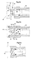
- Figs. 4A and 4B which are cross-sectional views similar to Figs. 2A and 2B, show the tool element and the tightening device at the interchanging position.
- a gripping implement 55 of the machine presses the attachment tap 13 of the tool element 10 down against the entering cone 51 of the head 50.
- the balls 52, 53 compress the respective spring during this pressing because the hole wall of the attachment tap 13 slides on the balls.
- the tool element is coarsely centered in radial direction by the abutment of the stop pin 33 against the upper end surface of the head 50. The balls will simultaneously snap into the corresponding recesses in the hole wall such that the gripping implement may be withdrawn.
- the stop pin 35 may be replaced by a resilient pin arranged in the center line, which projects into a recess in the front surface of the head 50 or such that the pin is provided in the head for projection into a recess in the tool shank.
- the tool element is coaxially aligned with the center line CL of the inner pipe 40 because of the sliding of the balls 52,53 on the wall of the hole 25 so that the cylindrical attachment tap 13 finally may enter into the space 42 of the inner pipe.
- Figs. 5A, 5B which are cross-sectional views similar to Figs. 2A and 2B, the tool element 10 and the tightening device are shown in the working position, wherein the pull rod 41 has been tightened.
- the projections 15, 16 which enclose the neck 49 and the head 50 will expand in the transversal direction of the tightening device during the tightening of the pull rod 41 so that the projections will be exposed to a press power directed transversely to the center line CL of the inner pipe 40 opposite to the these and therefore a safe connection free from play is achieved.
- the end surface 12 is brought to abutment on the end surface 43 of the inner pipe 4 0 at the tightening which defines the axial position of the tool element.
- the pins 44, 45 are received by the re- Completes 34, 35 in the end surface 12 of the tool element.
- F ig. 6 shows a cross-section of the tool mounting mainly corresponding to the diagonal I in Fig. 1A but without the pull rod for ease of illustration only.
- the projections 15, 16 of the tool element 10 has been partly pulled into the inner pipe 40.
- the primary guiding surfaces 19, 20 cause a m i d -centering of the tool element 10 against the guiding surface 42' in the space 42 in the inner pipe 40.
- the primary guiding surfaces 19, 20 will slip fit into the complementary guiding surface 42'' in the space 42.
- the two peripheral, cylindrical guiding surfaces 42', 42'' have different diameters complementary to the radii r 2' r 3 of the tap 13 and therefore jamming is avoided in spite of the fine fit.
- the inwards pulling also results in that the end surface 12 abuts against the end surface 43 of the inner pipe 40, which makes an ex- p ans i on of the projections 15, 16 in the space 42 possible.
- the tool element 10 will therefore be secured to the spindle with freedom from play in a finally centered position.
- Fluid passages 56, 57 transfer fluid from the machine towards the tool via the fluid passages 36, 37 in the tool element 10.
- the above described preferred embodiment comprises a pull rod having an end portion engaging the attachment tap, which is in the shape of a cylindrical, rounded enlargement it is io be understood that other alternative embodiments of the end portion of the pull rod are possible.
- the described device is not limited for use only in rotary spindles but may with advantage be used also in stationary fastening devices, for example for fastening of lathe bars.
- the invention relates to a tool mounting for a tool, which comprises a tool element or a tool shank and a tightening device arranged in the machine spindle.
- the tool mounting makes changes of tool units in a rotary spindle in a lathe possible with the same gripping appliances used for the lathe units and also use of the same magazines as for these.
Landscapes
- Engineering & Computer Science (AREA)
- Mechanical Engineering (AREA)
- Gripping On Spindles (AREA)
- Automatic Tool Replacement In Machine Tools (AREA)
- Jigs For Machine Tools (AREA)
- Cutting Tools, Boring Holders, And Turrets (AREA)
Applications Claiming Priority (2)
| Application Number | Priority Date | Filing Date | Title |
|---|---|---|---|
| SE8402831 | 1984-05-25 | ||
| SE8402831A SE455059B (sv) | 1984-05-25 | 1984-05-25 | Verktygskoppling mellan ett skerverktyg och en maskinspindel |
Publications (3)
| Publication Number | Publication Date |
|---|---|
| EP0162824A2 true EP0162824A2 (fr) | 1985-11-27 |
| EP0162824A3 EP0162824A3 (en) | 1987-07-22 |
| EP0162824B1 EP0162824B1 (fr) | 1990-11-07 |
Family
ID=20356033
Family Applications (1)
| Application Number | Title | Priority Date | Filing Date |
|---|---|---|---|
| EP85850169A Expired - Lifetime EP0162824B1 (fr) | 1984-05-25 | 1985-05-13 | Montage d'outil |
Country Status (5)
| Country | Link |
|---|---|
| US (1) | US4642006A (fr) |
| EP (1) | EP0162824B1 (fr) |
| JP (1) | JPS6114830A (fr) |
| DE (1) | DE3580395D1 (fr) |
| SE (1) | SE455059B (fr) |
Cited By (3)
| Publication number | Priority date | Publication date | Assignee | Title |
|---|---|---|---|---|
| DE3608141A1 (de) * | 1986-03-12 | 1987-09-17 | Heller Geb Gmbh Maschf | Werkzeug fuer werkzeugwechsel-maschinen |
| DE3712820A1 (de) * | 1987-04-15 | 1988-11-03 | Axa Entwicklung Maschinenbau | Werkzeugmaschine mit werkzeugwechseleinrichtung |
| WO1993010930A1 (fr) * | 1991-12-03 | 1993-06-10 | Komet Präzisionswerkzeuge Robert Breuning Gmbh | Dispositif d'accouplement pour outils, presentant un manchon de raccordement pouvant etre elargi radialement de maniere elastique, ainsi qu'une tige avec un element de serrage |
Families Citing this family (3)
| Publication number | Priority date | Publication date | Assignee | Title |
|---|---|---|---|---|
| DE4123966A1 (de) * | 1991-07-19 | 1993-01-21 | Heller Geb Gmbh Maschf | Spannvorrichtung fuer einzelwerkzeuge |
| JPH0541646U (ja) * | 1991-11-12 | 1993-06-08 | ユーエイチテイー株式会社 | ツールホルダの取付け構造 |
| DE102007036786A1 (de) * | 2007-04-19 | 2008-10-23 | Robert Bosch Gmbh | Adapter für eine motorisch angetriebene Werkzeugmaschine mit drehbar anzutreibendem Werkzeug |
Family Cites Families (12)
| Publication number | Priority date | Publication date | Assignee | Title |
|---|---|---|---|---|
| DE1552556B1 (de) * | 1965-11-03 | 1971-02-18 | Schmid Maschb Kg | Zentrierung von Werkzeugen oder Werkzeughaltern in bzw. auf der Spindel von Werkzeugmaschinen |
| US3587165A (en) * | 1969-02-10 | 1971-06-28 | Kearney & Trecker Corp | Tool selector with magazine |
| DE2234676C2 (de) * | 1972-07-14 | 1975-02-27 | Gildemeister Ag, 4800 Bielefeld | Anordnung zum Wechseln von mit Werkzeugen bestückten Werkzeughaltern an einer Werkzeugmaschine |
| DE2741802A1 (de) * | 1977-09-16 | 1979-04-12 | Gerhard Stark | Revolverbohrmaschine |
| SE433574B (sv) * | 1978-09-26 | 1984-06-04 | Sandvik Ab | Skerverktyg och verktygselement for detta |
| SE423875B (sv) * | 1979-02-07 | 1982-06-14 | Sandvik Ab | Verktygskoppling mellan ett skervertkyg och en maskinspindel |
| DE3007440A1 (de) * | 1980-02-28 | 1981-09-17 | Fried. Krupp Gmbh, 4300 Essen | Werkzeugeinrichtung mit wechselbarem werkzeugtraeger |
| FR2493747A1 (fr) * | 1980-11-07 | 1982-05-14 | Ernault Somua H | Machine-outil a commande numerique avec magasin d'outils |
| US4521950A (en) * | 1981-08-13 | 1985-06-11 | O-M Limited | Automatic tool change machine tool |
| FR2521888A1 (fr) * | 1982-02-19 | 1983-08-26 | Ernault Somua H | Systeme de blocage d'outils sur un plateau rotatif indexable |
| DE3318603A1 (de) * | 1983-05-21 | 1984-11-22 | Sauter Feinmechanik GmbH, 7430 Metzingen | Werkzeughalter fuer eine werkzeugmaschine, insbesondere fuer eine drehmaschine |
| US4580472A (en) * | 1983-07-23 | 1986-04-08 | Kastner Hermann L | Cutting tool with interchangeable tool head for machine tools |
-
1984
- 1984-05-25 SE SE8402831A patent/SE455059B/sv not_active IP Right Cessation
-
1985
- 1985-05-13 DE DE8585850169T patent/DE3580395D1/de not_active Expired - Lifetime
- 1985-05-13 EP EP85850169A patent/EP0162824B1/fr not_active Expired - Lifetime
- 1985-05-20 US US06/735,763 patent/US4642006A/en not_active Expired - Lifetime
- 1985-05-24 JP JP60110578A patent/JPS6114830A/ja active Pending
Cited By (4)
| Publication number | Priority date | Publication date | Assignee | Title |
|---|---|---|---|---|
| DE3608141A1 (de) * | 1986-03-12 | 1987-09-17 | Heller Geb Gmbh Maschf | Werkzeug fuer werkzeugwechsel-maschinen |
| DE3712820A1 (de) * | 1987-04-15 | 1988-11-03 | Axa Entwicklung Maschinenbau | Werkzeugmaschine mit werkzeugwechseleinrichtung |
| US4976575A (en) * | 1987-04-15 | 1990-12-11 | AXA-Entwicklungs- und Maschinenbau- gesellschaft fur produktionstechnisch e anlagen und Gerate mbH | Tool holding system for automatic tool changing |
| WO1993010930A1 (fr) * | 1991-12-03 | 1993-06-10 | Komet Präzisionswerkzeuge Robert Breuning Gmbh | Dispositif d'accouplement pour outils, presentant un manchon de raccordement pouvant etre elargi radialement de maniere elastique, ainsi qu'une tige avec un element de serrage |
Also Published As
| Publication number | Publication date |
|---|---|
| SE8402831D0 (sv) | 1984-05-25 |
| SE455059B (sv) | 1988-06-20 |
| SE8402831L (sv) | 1985-11-26 |
| JPS6114830A (ja) | 1986-01-23 |
| EP0162824B1 (fr) | 1990-11-07 |
| US4642006A (en) | 1987-02-10 |
| DE3580395D1 (de) | 1990-12-13 |
| EP0162824A3 (en) | 1987-07-22 |
Similar Documents
| Publication | Publication Date | Title |
|---|---|---|
| US4673319A (en) | Major-minor tool shank for machine tool | |
| KR100289138B1 (ko) | 공작기계의 자동공구교환장치 | |
| CA1260687A (fr) | Accouplement de tete d'outil et porte-outil | |
| US5806859A (en) | Self-contained collet adaptor | |
| JP3310148B2 (ja) | アタッチメント及びアタッチメントの割出し方法並びに自動工具交換装置 | |
| US4976575A (en) | Tool holding system for automatic tool changing | |
| CA1218255A (fr) | Prise mecanique pour porte-outil | |
| US4197771A (en) | Quick change device for mounting tool in support member | |
| CA2133655A1 (fr) | Tourelle universelle permettant de changer rapidement l'outil sur un tour | |
| US4547101A (en) | Self-aligning tool holder | |
| US6219893B1 (en) | Coupling for clamping a pallet | |
| JPH02243209A (ja) | 工作機械主軸用工具アダプタ | |
| US4642006A (en) | Tool mounting | |
| US4777714A (en) | Quick-change mount for chucks | |
| US4684301A (en) | Machine tool spindle and tool holder | |
| US6183404B1 (en) | Machine tool for machining cavities in workpieces | |
| EP0564296B1 (fr) | Appareil pour la broche principale d'une machine outil | |
| US4700442A (en) | Tool changing apparatus for a machine tool | |
| GB1601010A (en) | Machine tool having a cleaning means | |
| US4167362A (en) | Multiple tool driving turret attachment | |
| US4768282A (en) | Tooling quick release/change apparatus | |
| EP1543904A2 (fr) | Porte outil | |
| GB2162105A (en) | Tapper | |
| US4641414A (en) | Pallet for seating interchangeable clamping jaws of a chuck | |
| US4939834A (en) | Machine tool with tool change mechanism |
Legal Events
| Date | Code | Title | Description |
|---|---|---|---|
| PUAI | Public reference made under article 153(3) epc to a published international application that has entered the european phase |
Free format text: ORIGINAL CODE: 0009012 |
|
| AK | Designated contracting states |
Designated state(s): DE FR GB IT |
|
| 17P | Request for examination filed |
Effective date: 19860521 |
|
| PUAL | Search report despatched |
Free format text: ORIGINAL CODE: 0009013 |
|
| AK | Designated contracting states |
Kind code of ref document: A3 Designated state(s): DE FR GB IT |
|
| 17Q | First examination report despatched |
Effective date: 19881209 |
|
| GRAA | (expected) grant |
Free format text: ORIGINAL CODE: 0009210 |
|
| AK | Designated contracting states |
Kind code of ref document: B1 Designated state(s): DE FR GB IT |
|
| PG25 | Lapsed in a contracting state [announced via postgrant information from national office to epo] |
Ref country code: IT Free format text: LAPSE BECAUSE OF FAILURE TO SUBMIT A TRANSLATION OF THE DESCRIPTION OR TO PAY THE FEE WITHIN THE PRESCRIBED TIME-LIMIT;WARNING: LAPSES OF ITALIAN PATENTS WITH EFFECTIVE DATE BEFORE 2007 MAY HAVE OCCURRED AT ANY TIME BEFORE 2007. THE CORRECT EFFECTIVE DATE MAY BE DIFFERENT FROM THE ONE RECORDED. Effective date: 19901107 Ref country code: FR Effective date: 19901107 |
|
| REF | Corresponds to: |
Ref document number: 3580395 Country of ref document: DE Date of ref document: 19901213 |
|
| EN | Fr: translation not filed | ||
| PLBE | No opposition filed within time limit |
Free format text: ORIGINAL CODE: 0009261 |
|
| STAA | Information on the status of an ep patent application or granted ep patent |
Free format text: STATUS: NO OPPOSITION FILED WITHIN TIME LIMIT |
|
| 26N | No opposition filed | ||
| PGFP | Annual fee paid to national office [announced via postgrant information from national office to epo] |
Ref country code: DE Payment date: 20010508 Year of fee payment: 17 |
|
| PGFP | Annual fee paid to national office [announced via postgrant information from national office to epo] |
Ref country code: GB Payment date: 20010509 Year of fee payment: 17 |
|
| REG | Reference to a national code |
Ref country code: GB Ref legal event code: IF02 |
|
| PG25 | Lapsed in a contracting state [announced via postgrant information from national office to epo] |
Ref country code: GB Free format text: LAPSE BECAUSE OF NON-PAYMENT OF DUE FEES Effective date: 20020513 |
|
| PG25 | Lapsed in a contracting state [announced via postgrant information from national office to epo] |
Ref country code: DE Free format text: LAPSE BECAUSE OF NON-PAYMENT OF DUE FEES Effective date: 20021203 |
|
| GBPC | Gb: european patent ceased through non-payment of renewal fee |
Effective date: 20020513 |