EP0163012A2 - Dispositif pour tourner des manchons avec des tubes - Google Patents
Dispositif pour tourner des manchons avec des tubes Download PDFInfo
- Publication number
- EP0163012A2 EP0163012A2 EP85102217A EP85102217A EP0163012A2 EP 0163012 A2 EP0163012 A2 EP 0163012A2 EP 85102217 A EP85102217 A EP 85102217A EP 85102217 A EP85102217 A EP 85102217A EP 0163012 A2 EP0163012 A2 EP 0163012A2
- Authority
- EP
- European Patent Office
- Prior art keywords
- machine according
- sleeve
- screwing machine
- screwing
- pliers
- Prior art date
- Legal status (The legal status is an assumption and is not a legal conclusion. Google has not performed a legal analysis and makes no representation as to the accuracy of the status listed.)
- Granted
Links
Images


Classifications
-
- E—FIXED CONSTRUCTIONS
- E21—EARTH OR ROCK DRILLING; MINING
- E21B—EARTH OR ROCK DRILLING; OBTAINING OIL, GAS, WATER, SOLUBLE OR MELTABLE MATERIALS OR A SLURRY OF MINERALS FROM WELLS
- E21B19/00—Handling rods, casings, tubes or the like outside the borehole, e.g. in the derrick; Apparatus for feeding the rods or cables
- E21B19/16—Connecting or disconnecting pipe couplings or joints
-
- B—PERFORMING OPERATIONS; TRANSPORTING
- B23—MACHINE TOOLS; METAL-WORKING NOT OTHERWISE PROVIDED FOR
- B23P—METAL-WORKING NOT OTHERWISE PROVIDED FOR; COMBINED OPERATIONS; UNIVERSAL MACHINE TOOLS
- B23P19/00—Machines for simply fitting together or separating metal parts or objects, or metal and non-metal parts, whether or not involving some deformation; Tools or devices therefor so far as not provided for in other classes
- B23P19/04—Machines for simply fitting together or separating metal parts or objects, or metal and non-metal parts, whether or not involving some deformation; Tools or devices therefor so far as not provided for in other classes for assembling or disassembling parts
- B23P19/06—Screw or nut setting or loosening machines
- B23P19/061—Screw or nut setting or loosening machines for pipes or pipe-couplings
Definitions
- the invention relates to a socket screwing machine for pipes with screwing pliers fastened on a common base frame and a pipe wrench (counter device).
- Pipe sleeves serve as connecting elements, which are screwed to the pipes before being inserted into the bore. The screwing in the vertical pipe position and the subsequent drawing into the bore is known. A device suitable for this is described for example in DE-PS 31 38 870.
- the invention has for its object to provide a sleeve screwing machine that automatically carries out the screwing process without interruption starting with the fitting of the sleeve until it is screwed tight in one operation, thereby significantly reducing the cycle times.
- the solution according to the invention is characterized in that one of the pliers is fixed in position on the common base frame and the other horizontally transversely to the tube axis and vertically compensatory and movable to change the distance between the pliers on the base frame.
- the pipe wrench is preferably movable and the screwing pliers are stationary. It is particularly advantageous to mount the pipe wrench vertically displaceably in a guide frame and to fill it with it so that it can move across the pipe axis.
- the horizontal transverse mobility of the guide frame can be achieved by laterally projecting holding arms which are rotatably supported on guide bushes of a sliding guide pointing in the direction of the tube axis.
- the axes of the rotatable support points of the holding arms are arranged in the horizontal plane of the tube axis.
- the outer ends of the holding arms are connected to one another by rods, which in turn are mounted in oscillating connecting webs of the guide bushings. Starting from these connecting webs, the holding arms reach under the pipe to be screwed. At the lowest point they meet and get a V-shape.
- the socket screwing machine designed according to the invention makes the use of the otherwise usual socket pre-screwing machine superfluous.
- the cycle of cycles is reduced to a minimum, so that exceptionally high performances are possible, for example in the case of smaller units, over two hundred complete screw connections per hour.
- the machine allows a fully automatic screwing process with controlled threading, stepless speed control, torque limitation and reproducible connection, both for screw connections with a path specification and torque control as well as with a torque specification and path control.
- Pipe / socket tolerances are compensated for by the path-dependent control and the compensatable suspension of the pipe wrench.
- the machine is suitable for pipe producers as well as for use in pipe overhauls.
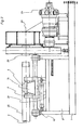
- a feed system also not shown, on the back of the screwing pliers 5 promotes a fat Tete sleeve 26 in the screwing pliers 5, which begins to rotate with the initiation of the clamping process.
- the entire pipe wrench in the guide frame 7 is raised by the lifting cylinder 21 until the pipe axis 6 and the sleeve axis 29 are aligned.
- the pipe wrench 4 with the pipe then moves through the actuation of the feed cylinder 20, provided with a proportional speed control, towards the sleeve 26.
- a light barrier is passed through which specifies the reference point for the electronic path measurement. In this way, tolerances from the positioning can be compensated for.
- the pipe wrench 4 is lowered by retracting the cylinder 21. This causes the threads of the pipe and pipe socket to come into contact on one side, i.e. H. the lower part of the pipe thread engages in the socket thread. Due to the screwing rotations, the pipe is pulled further into the socket, whereby the pipe inevitably rises above the threaded cone of the connecting screw connection until the axes of the two parts to be screwed are in line again. With suitable threads, direct screwing is also possible without first lowering the pipe wrench.
- the further screw connection is controlled by the electronic path measurement and carried out until the end of the defined path specification.
- a kinematic reversal of the arrangement is also possible, i. H. the pipe wrench 4 can be stationary and the screwing pliers 5 can be moved and suspended in such a way that they can carry out compensatory movements.
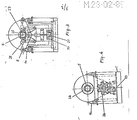
- the holding arms 8 of the guide frame 7 are connected to one another by connecting rods 13 and, at the same time, are supported by the latter on the rocker-shaped connecting webs 14. Appropriate mounting means that they can rotate and allow the guide arms to be moved laterally.
- the axes 11 of the connecting and support rods lie in the horizontal plane 12 of the pipe axis 6. This position avoids transverse forces which load the thread during the screwing operation, since pure pulling force acts on one articulation point and pure pressure force acts on the opposite one.
- the screwing pliers 5 are suspended from the machine housing 3 in a pendulum manner via a ball slewing ring 22, so that the torque can be measured at the lower end of the screwing pliers via the strain gauge 23.
- the screwing pliers 5 can also be integrated into the machine housing 3. In this case, the torque is measured via a measuring shaft.
- the screwing speed and the holding time are freely programmable.
- the hydraulic motor switches off and the sleeve tension is released in the opposite direction.
- the pipe wrench moves back into the starting position, at the same time the clamping blocks are released and the pipe with the sleeve attached is released.
- a radial piston motor with adjustable eccentricity, a reduction gear and control elements for the screw drive are provided.
- electro-hydraulic drive there is also the option of replacing the electro-hydraulic drive with a controllable DC motor.
- the screwing machine enables a fully automatic workflow, starting with the supply of pipes and sockets via the supply or handling systems, not shown. It brings a very significant reduction in cycle times and is therefore of particular importance for series production.
Landscapes
- Engineering & Computer Science (AREA)
- Geology (AREA)
- Life Sciences & Earth Sciences (AREA)
- Mechanical Engineering (AREA)
- Mining & Mineral Resources (AREA)
- Physics & Mathematics (AREA)
- Environmental & Geological Engineering (AREA)
- Fluid Mechanics (AREA)
- General Life Sciences & Earth Sciences (AREA)
- Geochemistry & Mineralogy (AREA)
- Automatic Assembly (AREA)
- Earth Drilling (AREA)
- Supports For Pipes And Cables (AREA)
- Paper (AREA)
Priority Applications (1)
| Application Number | Priority Date | Filing Date | Title |
|---|---|---|---|
| AT85102217T ATE63487T1 (de) | 1984-03-22 | 1985-02-28 | Muffenverschraubungsmaschine fuer rohre. |
Applications Claiming Priority (2)
| Application Number | Priority Date | Filing Date | Title |
|---|---|---|---|
| DE3410561A DE3410561C2 (de) | 1984-03-22 | 1984-03-22 | Maschine zum horizontalen Verschrauben und Lösen von Muffenverbindungen |
| DE3410561 | 1984-03-22 |
Publications (3)
| Publication Number | Publication Date |
|---|---|
| EP0163012A2 true EP0163012A2 (fr) | 1985-12-04 |
| EP0163012A3 EP0163012A3 (en) | 1988-01-13 |
| EP0163012B1 EP0163012B1 (fr) | 1991-05-15 |
Family
ID=6231307
Family Applications (1)
| Application Number | Title | Priority Date | Filing Date |
|---|---|---|---|
| EP85102217A Expired - Lifetime EP0163012B1 (fr) | 1984-03-22 | 1985-02-28 | Dispositif pour tourner des manchons avec des tubes |
Country Status (4)
| Country | Link |
|---|---|
| EP (1) | EP0163012B1 (fr) |
| JP (1) | JPH0643791B2 (fr) |
| AT (1) | ATE63487T1 (fr) |
| DE (1) | DE3410561C2 (fr) |
Cited By (7)
| Publication number | Priority date | Publication date | Assignee | Title |
|---|---|---|---|---|
| RU2514356C2 (ru) * | 2012-08-07 | 2014-04-27 | Открытое акционерное общество Уральский научно-исследовательский технологический институт (ОАО УралНИТИ) | Станок для довертывания элементов замков на концах трубы |
| CN107855750A (zh) * | 2017-11-22 | 2018-03-30 | 广东金弘达自动化科技股份有限公司 | 一种应用于led针脚套管机的套管机构 |
| CN108326539A (zh) * | 2018-01-23 | 2018-07-27 | 秦皇岛润昌科技开发有限公司 | 一种石油及天然气开采用螺杆钻具辅助拆装设备 |
| CN110227931A (zh) * | 2019-07-10 | 2019-09-13 | 无锡亿莱特科技有限公司 | 一种高效智能石油保护套拧接机 |
| CN111167969A (zh) * | 2020-01-20 | 2020-05-19 | 中铁上海工程局集团有限公司 | 一种轨枕套管螺旋筋的旋拧装置 |
| CN111594076A (zh) * | 2020-05-16 | 2020-08-28 | 扬州市江隆矿业设备有限公司 | 一种近水平螺旋钻杆机钻杆套管安装装置 |
| CN112318102A (zh) * | 2020-11-12 | 2021-02-05 | 格力电器(重庆)有限公司 | 一种螺母锁敷装置 |
Families Citing this family (7)
| Publication number | Priority date | Publication date | Assignee | Title |
|---|---|---|---|---|
| JPH02107440U (fr) * | 1989-02-10 | 1990-08-27 | ||
| JP5862958B2 (ja) * | 2012-10-23 | 2016-02-16 | 株式会社デンソー | ネジ組立て装置 |
| CN109079465B (zh) * | 2018-11-01 | 2019-10-25 | 珠海格力电器股份有限公司 | 上料机构及具有其的连接管生产设备 |
| CN109605010B (zh) * | 2018-12-26 | 2024-01-05 | 北京好运达智创科技有限公司 | 一种套管和螺旋筋的自动装配系统 |
| CN116765807B (zh) * | 2023-07-31 | 2025-10-17 | 武汉合美达智能装备有限公司 | 一种螺栓拧紧抓手 |
| CN118321882B (zh) * | 2024-06-13 | 2024-08-23 | 江西东锐智能装备科技股份有限公司 | 一种潜孔钻机用自动卸杆装置 |
| CN119910419B (zh) * | 2025-03-12 | 2025-10-03 | 中国科学院沈阳自动化研究所 | 一种大长径比舱段全自动螺纹结合装置 |
Family Cites Families (9)
| Publication number | Priority date | Publication date | Assignee | Title |
|---|---|---|---|---|
| US3298089A (en) * | 1964-06-01 | 1967-01-17 | Wm K Stamets Company | Coupling screw-on-machine |
| DE2124629C3 (de) * | 1971-05-18 | 1974-01-10 | Th. Kieserling & Albrecht, 5650 Solingen | Verfahren zum automatischen Aufschrauben einer mit konischem Innengewinde versehenen Muffe auf ein Rohr mit entsprechendem Aussengewinde |
| DE2559674A1 (de) * | 1975-11-06 | 1977-06-08 | Preyer Kg Karl | Schlauchmontage-vorrichtung |
| DE2618877C3 (de) * | 1976-04-29 | 1981-04-30 | Christensen, Inc., 84114 Salt Lake City, Utah | Vorrichtung zum Kontern und Brechen der Gewindeverbindungen zwischen Rohrkörpern |
| US4092881A (en) * | 1976-10-29 | 1978-06-06 | Christensen, Inc. | Apparatus for making-up and breaking threaded pipe connections |
| GB2035869B (en) * | 1978-12-01 | 1982-10-13 | Kehlenbeck F | Screwing up on threadchasing machine |
| NL7903701A (nl) * | 1979-05-10 | 1980-11-12 | Kwa Automationsanlagen Wiesbad | Werkwijze en inrichting voor het opschroeven van buismoffen. |
| GB2123328B (en) * | 1982-05-15 | 1986-06-11 | Mach Tool Engineers | A hydraulic torque machine |
| DE3234027C1 (de) * | 1982-09-14 | 1984-01-19 | Christensen, Inc., 84115 Salt Lake City, Utah | Vorrichtung zum Kontern und Brechen von Gewindeverbindungen |
-
1984
- 1984-03-22 DE DE3410561A patent/DE3410561C2/de not_active Expired
-
1985
- 1985-02-28 AT AT85102217T patent/ATE63487T1/de active
- 1985-02-28 EP EP85102217A patent/EP0163012B1/fr not_active Expired - Lifetime
- 1985-03-22 JP JP60055735A patent/JPH0643791B2/ja not_active Expired - Lifetime
Cited By (9)
| Publication number | Priority date | Publication date | Assignee | Title |
|---|---|---|---|---|
| RU2514356C2 (ru) * | 2012-08-07 | 2014-04-27 | Открытое акционерное общество Уральский научно-исследовательский технологический институт (ОАО УралНИТИ) | Станок для довертывания элементов замков на концах трубы |
| CN107855750A (zh) * | 2017-11-22 | 2018-03-30 | 广东金弘达自动化科技股份有限公司 | 一种应用于led针脚套管机的套管机构 |
| CN107855750B (zh) * | 2017-11-22 | 2023-08-04 | 广东凌云智造科技股份有限公司 | 一种应用于led针脚套管机的套管机构 |
| CN108326539A (zh) * | 2018-01-23 | 2018-07-27 | 秦皇岛润昌科技开发有限公司 | 一种石油及天然气开采用螺杆钻具辅助拆装设备 |
| CN110227931A (zh) * | 2019-07-10 | 2019-09-13 | 无锡亿莱特科技有限公司 | 一种高效智能石油保护套拧接机 |
| CN111167969A (zh) * | 2020-01-20 | 2020-05-19 | 中铁上海工程局集团有限公司 | 一种轨枕套管螺旋筋的旋拧装置 |
| CN111594076A (zh) * | 2020-05-16 | 2020-08-28 | 扬州市江隆矿业设备有限公司 | 一种近水平螺旋钻杆机钻杆套管安装装置 |
| CN111594076B (zh) * | 2020-05-16 | 2021-06-01 | 扬州市江隆矿业设备有限公司 | 一种近水平螺旋钻杆机钻杆套管安装装置 |
| CN112318102A (zh) * | 2020-11-12 | 2021-02-05 | 格力电器(重庆)有限公司 | 一种螺母锁敷装置 |
Also Published As
| Publication number | Publication date |
|---|---|
| EP0163012A3 (en) | 1988-01-13 |
| EP0163012B1 (fr) | 1991-05-15 |
| ATE63487T1 (de) | 1991-06-15 |
| JPS61111861A (ja) | 1986-05-29 |
| JPH0643791B2 (ja) | 1994-06-08 |
| DE3410561A1 (de) | 1985-10-03 |
| DE3410561C2 (de) | 1986-04-03 |
Similar Documents
| Publication | Publication Date | Title |
|---|---|---|
| EP3871829B1 (fr) | Procédé de serrage de raccords à vis, dispositif à vis multiples | |
| EP0163012A2 (fr) | Dispositif pour tourner des manchons avec des tubes | |
| DE68926716T2 (de) | Apparatur zum verbinden und lösen geschraubter teile | |
| EP3550139A1 (fr) | Dispositif de serrage de raccords vissés | |
| DE3890753C2 (de) | Apparat zum Drehen eines rohrförmigen Bohrungselements um seine Längsachse | |
| WO2000054904A1 (fr) | Systeme de transport | |
| DE3541922C1 (de) | Rohrmuffenaufschraubmaschine | |
| DE2312968C2 (de) | Vorrichtung zum Verschrauben von Elektrodenabschnitten in einem Ofen | |
| DE69009446T2 (de) | Werkzeug für biegepresse zum freibiegen. | |
| DE2411744C3 (de) | Presse zum Pressverbinden eines Kabels oder isolierten Drahtes mit einem Kabelschuh | |
| DE3138954A1 (de) | Palettenregistermechanismus und transferhubsystem | |
| EP3242119A1 (fr) | Dispositif d'analyse de la capacité portante de roue dentée et procédé d'analyse de la capacité portante de roue dentée | |
| DE10344352B4 (de) | Bohrgerät und Verfahren zum Einbringen eines Bohrelementes in den Boden | |
| EP0015931A1 (fr) | Procede et dispositif pour le vissage de manchons tubulaires | |
| DE102014111683B4 (de) | Pressenantrieb für eine Umformvorrichtung | |
| DE69012966T2 (de) | Kontinuierliches Ziehverfahren zum Geradeziehen und Vorrichtung zur Durchführung des Verfahrens. | |
| DE69001771T2 (de) | Anordnung zur Handhabung von Bohrstangen in einem Gesteinsbohraggregat oder dgl. | |
| DE833504C (de) | Vorrichtung zum Spannen eines Seiles, insbesondere eines Drahtseiles bei Seilbahnen | |
| DE10339004A1 (de) | Hydraulische Presse | |
| DE4025929C2 (de) | Spannvorrichtung für das Leitrad von Kettenfahrzeugen | |
| WO2004080627A1 (fr) | Machine plieuse destinee notamment a des tables de soudage ou de serrage, table de soudage et table de serrage | |
| DE102009053437A1 (de) | Spannbacke | |
| DE3031640C2 (fr) | ||
| DE2817017C2 (de) | Horizontalpreßbohrgerät | |
| DE19722287B4 (de) | Drahtvorschub- und Ziehvorrichtung |
Legal Events
| Date | Code | Title | Description |
|---|---|---|---|
| PUAI | Public reference made under article 153(3) epc to a published international application that has entered the european phase |
Free format text: ORIGINAL CODE: 0009012 |
|
| AK | Designated contracting states |
Designated state(s): AT FR GB IT |
|
| PUAL | Search report despatched |
Free format text: ORIGINAL CODE: 0009013 |
|
| AK | Designated contracting states |
Kind code of ref document: A3 Designated state(s): AT FR GB IT |
|
| 17P | Request for examination filed |
Effective date: 19880205 |
|
| 17Q | First examination report despatched |
Effective date: 19890613 |
|
| GRAA | (expected) grant |
Free format text: ORIGINAL CODE: 0009210 |
|
| AK | Designated contracting states |
Kind code of ref document: B1 Designated state(s): AT FR GB IT |
|
| REF | Corresponds to: |
Ref document number: 63487 Country of ref document: AT Date of ref document: 19910615 Kind code of ref document: T |
|
| GBT | Gb: translation of ep patent filed (gb section 77(6)(a)/1977) | ||
| ITF | It: translation for a ep patent filed | ||
| RAP2 | Party data changed (patent owner data changed or rights of a patent transferred) |
Owner name: WEATHERFORD PRODUCTS & EQUIPMENT GMBH |
|
| PLBE | No opposition filed within time limit |
Free format text: ORIGINAL CODE: 0009261 |
|
| STAA | Information on the status of an ep patent application or granted ep patent |
Free format text: STATUS: NO OPPOSITION FILED WITHIN TIME LIMIT |
|
| 26N | No opposition filed | ||
| REG | Reference to a national code |
Ref country code: GB Ref legal event code: 732 |
|
| PGFP | Annual fee paid to national office [announced via postgrant information from national office to epo] |
Ref country code: GB Payment date: 19950131 Year of fee payment: 11 |
|
| PGFP | Annual fee paid to national office [announced via postgrant information from national office to epo] |
Ref country code: FR Payment date: 19950215 Year of fee payment: 11 |
|
| PGFP | Annual fee paid to national office [announced via postgrant information from national office to epo] |
Ref country code: AT Payment date: 19950222 Year of fee payment: 11 |
|
| PG25 | Lapsed in a contracting state [announced via postgrant information from national office to epo] |
Ref country code: GB Effective date: 19960228 Ref country code: AT Effective date: 19960228 |
|
| GBPC | Gb: european patent ceased through non-payment of renewal fee |
Effective date: 19960228 |
|
| PG25 | Lapsed in a contracting state [announced via postgrant information from national office to epo] |
Ref country code: FR Effective date: 19961031 |
|
| REG | Reference to a national code |
Ref country code: FR Ref legal event code: ST |