EP0163025A2 - Dispositif d'emmagasinage pour un câble de connexion d'une installation centrale d'alimentation de réseau de bord - Google Patents
Dispositif d'emmagasinage pour un câble de connexion d'une installation centrale d'alimentation de réseau de bord Download PDFInfo
- Publication number
- EP0163025A2 EP0163025A2 EP85103001A EP85103001A EP0163025A2 EP 0163025 A2 EP0163025 A2 EP 0163025A2 EP 85103001 A EP85103001 A EP 85103001A EP 85103001 A EP85103001 A EP 85103001A EP 0163025 A2 EP0163025 A2 EP 0163025A2
- Authority
- EP
- European Patent Office
- Prior art keywords
- connecting cable
- winding drum
- winding
- section
- housing
- Prior art date
- Legal status (The legal status is an assumption and is not a legal conclusion. Google has not performed a legal analysis and makes no representation as to the accuracy of the status listed.)
- Granted
Links
Images

Classifications
-
- H—ELECTRICITY
- H02—GENERATION; CONVERSION OR DISTRIBUTION OF ELECTRIC POWER
- H02G—INSTALLATION OF ELECTRIC CABLES OR LINES, OR OF COMBINED OPTICAL AND ELECTRIC CABLES OR LINES
- H02G11/00—Arrangements of electric cables or lines between relatively-movable parts
- H02G11/02—Arrangements of electric cables or lines between relatively-movable parts using take-up reel or drum
-
- B—PERFORMING OPERATIONS; TRANSPORTING
- B65—CONVEYING; PACKING; STORING; HANDLING THIN OR FILAMENTARY MATERIAL
- B65H—HANDLING THIN OR FILAMENTARY MATERIAL, e.g. SHEETS, WEBS, CABLES
- B65H75/00—Storing webs, tapes, or filamentary material, e.g. on reels
- B65H75/02—Cores, formers, supports, or holders for coiled, wound, or folded material, e.g. reels, spindles, bobbins, cop tubes, cans, mandrels or chucks
- B65H75/34—Cores, formers, supports, or holders for coiled, wound, or folded material, e.g. reels, spindles, bobbins, cop tubes, cans, mandrels or chucks specially adapted or mounted for storing and repeatedly paying-out and re-storing lengths of material provided for particular purposes, e.g. anchored hoses, power cables
- B65H75/38—Cores, formers, supports, or holders for coiled, wound, or folded material, e.g. reels, spindles, bobbins, cop tubes, cans, mandrels or chucks specially adapted or mounted for storing and repeatedly paying-out and re-storing lengths of material provided for particular purposes, e.g. anchored hoses, power cables involving the use of a core or former internal to, and supporting, a stored package of material
- B65H75/44—Constructional details
- B65H75/4449—Arrangements or adaptations to avoid movable contacts or rotary couplings, e.g. by the use of an expansion chamber for a lenght of the cord or hose
-
- B—PERFORMING OPERATIONS; TRANSPORTING
- B65—CONVEYING; PACKING; STORING; HANDLING THIN OR FILAMENTARY MATERIAL
- B65H—HANDLING THIN OR FILAMENTARY MATERIAL, e.g. SHEETS, WEBS, CABLES
- B65H2701/00—Handled material; Storage means
- B65H2701/30—Handled filamentary material
- B65H2701/34—Handled filamentary material electric cords or electric power cables
Definitions
- the invention relates to a device for stowing the connection cable of a central vehicle electrical system with a winding drum, on which several layers of the connection cable can be wound next to each other in one plane.
- a device for stowing the connection cable of a central vehicle electrical system with a winding drum, on which several layers of the connection cable can be wound next to each other in one plane.
- Such a device is already known (DE-GM 8303469.2).
- the known device also contains a compensating drum arranged coaxially with it, which lies above the take-up drum. Between two drum flanges of the compensating drum there is a cable section which is connected to the radially inner end of the useful length of the winding section: When the useful length of the winding section is wound up and unwound, the compensating cable section has the shape of an opening or closing spiral.
- the compensation section has a relatively large length of approximately two thirds of the length of the winding section.
- a long cable is therefore required, only part of which can be pulled out for connection to airplanes.
- the part that cannot be wound up takes up space and must be held by a correspondingly strong supporting structure.
- the invention has for its object to develop a device of the type described in the opening paragraph in such a way that a particularly large part of the connecting cable is available for winding and unwinding with the simplest possible structure.
- connection cable is deflected from an inside of the winding drum end of a winding section in an arc into the axis of rotation of the winding drum and that in a section extending in the axial direction of the winding drum, the connection cable is arranged spirally and when unwinding Winding section with a reduction of a radial expansion and weaker when winding with an increase in the radial expansion is spirally rotatable.
- connection cable has a section running in the direction of the axis of rotation of the winding drum, in which section a plurality of spiral turns are exposed in space.
- section a plurality of spiral turns are exposed in space.
- the connecting cable is exposed in this section, the stresses occurring during winding and unwinding can act on the spiral in such a way that it runs continuously. The stresses are therefore evenly distributed in this section of the connecting cable. For example, three to four turns of a spiral are sufficient to achieve a pull-out length of around 20 meters.
- the connecting cable is deflected in an arc from an end of a winding section lying inside the winding drum into the axis of rotation of the winding drum, and that the wires of the connection cable are exposed in a section extending in the axial direction of the winding drum and at Unwinding of the winding section with a reduction in a radial bulge can be twisted to a greater extent and weaker with each other during winding with an increase in the radial bulge.
- the connecting cable has a section in which the twisting of the individual cores is released to a certain extent when the connecting cable is wound up.
- the veins have a spiral course, with bulges of the veins. Towards the middle of the section, the veins have their greatest radial extension. Unwinding the connection cable from the winding drum increases the twisting of the wires in the section which runs in the direction of the axis of rotation. The stronger twisting results in a smaller radial expansion of the exposed wires.
- the section with the exposed wires is much shorter than the winding section.
- the section containing the exposed wires is preferably surrounded by a cylindrical housing, on the outside of which the winding drum is rotatably mounted.
- the bearings do not extend the axial extent of the device in this embodiment.
- the axial extent therefore essentially depends on the section with the exposed wires.
- the length of the section with the exposed wires and the radial width of the bulge depend on the number of turns that are necessary to unwind the connecting cable to the maximum length.
- the number of turns in turn depends on the diameter of the layers wound.
- the larger the diameter of the wound layers of the connecting cable the fewer turns are necessary to achieve the maximum unwinding length. This means that with larger diameters of the layers of the connecting cable, a smaller twist is sufficient for the maximum unwinding length.
- the winding drum contains two parallel drum disks which are connected to spokes which are rotatably supported at their inner ends by means of axial roller bearings on flanges projecting from the outside of the cylindrical housing.
- This arrangement is particularly suitable for the installation or suspension of the device in a position in which the axis of rotation of the winding drum is vertical.
- the spokes allow material to be saved.
- the winding drum can therefore be manufactured with a relatively low weight.
- An expedient embodiment is designed in such a way that the spokes of the winding drum are connected close to their inner edge with the edge of a downwardly projecting cylindrical pot which has a central opening through which the connecting cable is guided, which in a clamping part connected to the pot is attached.
- the pot closes the cylindrical housing, which is open at the bottom.
- the section with the exposed wires is therefore surrounded on all sides by walls.
- the veins are therefore in front Protected against contact and other external stresses. It is advantageous to guide the arc of the connecting cable in a holder attached to the bottom of the pot. The holder ensures that the shape of the sheet does not change substantially when the winding drum rotates.
- a drive wheel is arranged in the interior of the housing, which is positively connected to the bottom of the pot, has a central opening for the passage of the connecting cable and is connected to a drive unit which is attached to the outside of the housing.
- the drive wheel is located inside the cylindrical housing and is therefore against contact when opening and closing. Unwinding of the connection cable protected.
- the central opening can be made sufficiently wide so that exposed wires can already be present at the level of the drive wheel. When winding up the connection cable, the wires lie against the walls of the opening, which are expediently covered with an insulating material.
- the winding drum is connected via a chain to a geared motor which can be operated in two opposite directions of rotation.
- a geared motor which can be operated in two opposite directions of rotation.
- the cylindrical housing is expediently closed at its upper end and has a central passage for the connecting cable.
- the connection cable is at the upper end of the housing preferably again provided with the cable jacket, on the cross section of which the passage is matched. There are therefore no exposed wires outside the housing.
- the connecting cable can be clamped on the upper end of the housing, preferably on the outside.
- the housing is attached at its upper end to the underside of the head of a telescopic passenger boarding bridge. Complex, constructive measures for suspending the device are therefore not necessary.
- the drive wheel is expediently designed as a gearwheel and is arranged in the axial direction of the housing above the axial rolling bearings. At the level of the drive wheel, an opening is provided in the housing through which the chain runs.
- the outward opening of the winding drum is surrounded by a cylindrical cover which is fastened to the housing with supports and has an interruption at the outlet point of the connecting cable.
- the connection cable is therefore protected in the winding drum.
- a support roller for the connection cable is provided close to the interruption of the cover.
- the connecting cable is therefore always pulled off or wound onto the winding drum in the same place.
- the support roller prevents the connection cable from rubbing against the edges of the drum discs.
- the support roller, the z. B. has a concave surface adapted to the diameter of the connecting cable, is expediently mounted in a carrier attached to the housing.
- drum disks consist of individual sections with intermediate layers of insulating material.
- This embodiment is particularly suitable for cables with which larger powers in the medium frequency range, for. B. with 400 Hz, to largely avoid eddy current losses.
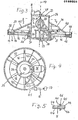
- a telescopic passenger boarding bridge 1, of which only the front part is shown in FIG. 1, contains a head 2, on the underside 3 of which a device 4 for stowing a connecting cable 5 of a central electrical system for aircraft is fastened.
- the device 4 is moved and adjusted horizontally and vertically with the passenger boarding bridge 1.
- the connecting cable 5 contains a winding section 6.
- the winding section 6 is located on a winding drum 7.
- the connecting cable 5 extends up to a distributor or junction box 8 fastened to the head 2.
- connection box 8 From the connection box 8, a connecting cable 9 is laid along the telescopic passenger boarding bridge 1.
- the connecting cable 9 is suspended from unspecified holders which are mounted in a longitudinally displaceable manner in a rail 10 in order to be able to adapt the length of the connecting cable 10 to the extended length of the passenger boarding bridge 1.
- the winding drum 7 contains two lateral, mutually parallel drum disks 11, 12, between which the connecting cable 5 is in the wound state.
- the distance between the two drum disks 11, 12 is so matched to the diameter of the connecting cable 5 that the wound layers 13, 14, 15 are located next to one another in one plane.
- the two drum disks 11, 12 are connected to one another and to spokes 16 at their edges facing the axis of rotation 17 by an unspecified ring.
- a piece 19 in front of the inner ends 18 of the spokes 16 begins an arc 19 of the connecting cable 5.
- the connecting cable 5 is deflected into the axis of rotation 17 of the winding drum 7.
- the spokes 16 are connected close to the inner ends 18 with the edge of a downwardly projecting cylindrical pot 20 which has a central opening 21 for the passage of the connecting cable 5.
- the pot 20 is rigidly attached to the spokes 16 and rotatable with them about the axis 17.
- the connecting cable 5 contains a section 22 which extends in the axial direction of the winding drum 7.
- the section 22 has a free, in the room arranged cable spiral, which is held at its ends in an opening of the winding drum 7.
- the cable spiral of section 22 consists of several, for. B. three to four, turns 47 which are arranged exposed in the space between the openings provided as guide and holding elements. In FIG. 2, one of the openings is designated by 26, while the other opening is not specified.
- the openings are arranged in the direction of the axis of rotation 17.
- the section 22 runs along the axis of rotation 17 of the winding drum 7 and is located in FIG a cylindrical housing 24, on the outside of which the winding drum 7 is rotatably mounted.
- the housing 24 is provided on its upper end face with a cover 25 which contains a central opening 26 for the passage of the connecting cable 5.
- a cable gland 27 is inserted, with which the connecting cable 5 is held, which is again surrounded at the level of the opening 26 by the unspecified outer cable jacket.
- the arc 19 of the connecting cable 5 is guided in a holder 28 attached to the outside of the bottom of the pot 20.
- the bracket 23 is off-center, i. H. arranged at a certain distance from the opening 21.
- the wires of the connecting cable 5 also run in a spiral.
- the radial expansion of the turns 47 of the cable spiral is greatest.
- the cable spiral is then the least twisted. It is possible that the number of turns 47 will decrease during winding.
- the winding section 6 is withdrawn from the winding drum 7, the windings 47 are again twisted together more.
- the radial extent is the smallest. Depending on the degree of twist, more turns may be present.
- the length of section 22, the radial extent and the number of turns 47 are matched to the layers 13, 14, 15 to be unwound and their diameters. With the cable spiral, an unwinding length of at least 18 m of cable can easily be achieved with three layers 13, 14, 15. With more layers, an even greater unwinding length can be achieved with appropriate adjustment of the cable spiral.
- the length of section 22 is approximately 0.5 m.
- the wires 23 of the connecting cable 7 are exposed in the section 22.
- the wires 23 can each consist of different conductors, which are surrounded by a common insulating sleeve.
- the wires 23 are lines which are assigned to the individual phases of a 400 Hz three-phase current and, among other things, control lines.
- control lines For example, in the connecting cable 5 seven wires for heavy current and at least six wires for control lines. With the outer jacket, which is removed at section 22, the connecting cable 5 has a diameter of about 46 mm. Numerous individual control lines can be located in the wires for control lines.
- the wires 23 run within the unsheathed cable sheath of the connecting cable 5 in a spiral. In section 22, the spiral course is weaker compared to the position within the cable jacket. When the winding section 6 is on the winding drum 7, the spiral shape of the wires 23 is weakest. The wires 23 are least twisted together and therefore have bulges 29 extending in the radial direction of the winding drum 7. When the take-up section 6 is pulled off the take-up drum 7, the wires 23 are twisted together again so that the radial extension of the bulges 29 is less.
- the length of the section 22 with the exposed wires 23 is matched to the number of layers 13, 14, 15 to be wound or unwound and their diameter.
- the twisting of the wires 23 must not be greater than the twisting present in a connecting cable 5 with a closed outer jacket.
- the length of the section 22 is preferably selected such that the twist when the winding section 6 is completely pulled off is somewhat less than the twist of the wires 23 within the closed outer cable sheath. If the diameter of the wound layers 13, 14, 15 is chosen to be larger, the length of the section 22 is therefore shorter. In general, a winding section 6 of 18 m length is sufficient. With a diameter of the middle layer 14 of approximately 1.6 to 2.4 m, the three layers 13, 14, 15 are sufficient to provide 18 m of cable after unwinding. The length of section 22 does not exceed about 0.6 to 0.4 m.
- the winding drum 7 is provided on the inner edges 18 of the spokes 16 with guideways 30, which face flanges 31 which protrude from the outside of the housing 24 of the winding drum 7.
- the guideways 30 and the flanges 31 form axial rolling bearings with balls or tons not shown. This arrangement is suitable for the vertical alignment of the axis of rotation 17.
- the drum disks 11, 12 extend in a horizontal direction.
- Rods 32 are attached to the inside of the bottom of the pot 20 and run concentrically and parallel to the axis of rotation 17.
- the rods 32 extend over a piece of the length of the section 22.
- a drive wheel 33 is attached to the ends of the rods 32 facing away from the bottom of the pot 20 and runs concentrically to the axis of rotation 17.
- the drive wheel 33 has a passage that can be matched to the bulge 29.
- the passage which is not described in more detail, expediently has on its walls a cladding made of an electrically insulating material, against which the wires 23 can lie.
- the drive wheel 33 is preferably designed as a gearwheel on which a chain 34 is mounted, which extends through an opening 35 in the housing 24.
- a drive unit 36 is fastened, which contains a geared motor (not designated in more detail), the output shaft of which carries a pinion 47 around which the chain 34 is placed.
- the geared motor can be switched to two opposite directions of rotation. If necessary, a torque is exerted on the winding drum 7 via the gear motor and the chain 34 when the connecting cable 5 is wound up or unwound becomes.
- the gear motor is switched on and off via a switch, not shown, which is located on a plug-in unit 37 which is attached to the end of the connecting cable 5.
- the connecting cable 5 is wound up or unwound with the gear motor switched on at the speed determined by the speed of the winding drum 7 and by the diameters of the layers 13, 14, 15. One person is sufficient for winding and unwinding.
- the winding drum 7 has an outwardly directed opening 33 between the drum disks 11, 12 which is opposed by a cylindrical cover 39 which has the shape of a ring.
- the cover 39 is fastened to the housing 24 with supports 40.
- the connection cable 5 is protected by the cover 39.
- the cover 39 has an interruption 41. At the point of the break 41, the connecting cable 5 emerges from the winding drum 7 approximately tangentially.
- a support roller 42 is provided near the interruption 41, on which the connecting cable 5 is guided.
- the top of the support roller 42 which can have a concave surface in order to guide the connecting cable 5, is located at the level of the drum disk 12.
- the connecting cable 5 is therefore always wound up and unwound at the same point.
- the support roller 42 prevents the maptei of the connecting cable 5 from rubbing against the edges of the drum disks 11, 12. In addition, an additional weight relief is created by the support roller 42.
- the support roller 42 is rotatably mounted in a carrier 43 which is fastened to the housing 24.
- the carrier 43 can also be a linkage.
- the drum disks 11, 12 are constructed from individual sections 44, the mutually facing ends 45 of which are angled. There are layers 46 of insulating material between the ends 45. The ends 45 are connected to each other by screws, not shown, which are guided in insulating sleeves, a short circuits switch off between adjacent sections 44.
- pressure rollers 48 are provided along the circumference of the winding drum 7 close to the opening 38 at an equal distance, which are rotatably mounted axially parallel to the axis of rotation 17.
- the pressure rollers 48 are preferably arranged in recesses 49 in the cover 39.
- the pressure rollers 48 protrude in the direction of the opening 38 beyond the inside of the cover 39.
Landscapes
- Storing, Repeated Paying-Out, And Re-Storing Of Elongated Articles (AREA)
- Electric Cable Arrangement Between Relatively Moving Parts (AREA)
- Storage Of Web-Like Or Filamentary Materials (AREA)
- Cable Accessories (AREA)
- Cable Transmission Systems, Equalization Of Radio And Reduction Of Echo (AREA)
Priority Applications (4)
| Application Number | Priority Date | Filing Date | Title |
|---|---|---|---|
| AT85103001T ATE54232T1 (de) | 1984-05-30 | 1985-03-15 | Vorrichtung zum verstauen des anschlusskabels einer zentralen bordnetzversorgungsanlage. |
| DE19853540940 DE3540940C2 (de) | 1985-03-15 | 1985-11-19 | Kabelanschlußvorrichtung zu einer zentralen Bordnetzversorgungsanlage für Flughäfen |
| EP86902367A EP0252914B1 (fr) | 1985-03-15 | 1986-03-14 | Dispositif de stockage du cable d'alimentation de preference d'un reseau d'alimentation de bord dans des aeroports |
| PCT/EP1986/000142 WO1986005632A1 (fr) | 1985-03-15 | 1986-03-14 | Dispositif de stockage du cable d'alimentation de preference d'un reseau d'alimentation de bord dans des aeroports |
Applications Claiming Priority (2)
| Application Number | Priority Date | Filing Date | Title |
|---|---|---|---|
| DE8416520U DE8416520U1 (de) | 1984-05-30 | 1984-05-30 | Vorrichtung zum Verstauen des Anschlußkabels einer zentralen Bordnetzversorgungsanlage |
| DE8416520U | 1984-05-30 |
Publications (3)
| Publication Number | Publication Date |
|---|---|
| EP0163025A2 true EP0163025A2 (fr) | 1985-12-04 |
| EP0163025A3 EP0163025A3 (en) | 1986-06-25 |
| EP0163025B1 EP0163025B1 (fr) | 1990-06-27 |
Family
ID=6767415
Family Applications (1)
| Application Number | Title | Priority Date | Filing Date |
|---|---|---|---|
| EP85103001A Expired - Lifetime EP0163025B1 (fr) | 1984-05-30 | 1985-03-15 | Dispositif d'emmagasinage pour un câble de connexion d'une installation centrale d'alimentation de réseau de bord |
Country Status (3)
| Country | Link |
|---|---|
| EP (1) | EP0163025B1 (fr) |
| AT (1) | ATE54232T1 (fr) |
| DE (2) | DE8416520U1 (fr) |
Cited By (6)
| Publication number | Priority date | Publication date | Assignee | Title |
|---|---|---|---|---|
| EP0252914B1 (fr) * | 1985-03-15 | 1989-06-28 | Manfred Fladung GmbH | Dispositif de stockage du cable d'alimentation de preference d'un reseau d'alimentation de bord dans des aeroports |
| EP0427041A3 (en) * | 1989-11-08 | 1991-11-21 | Manfred Fladung Gmbh | Cable winding device |
| WO1992001323A1 (fr) * | 1990-07-05 | 1992-01-23 | Manfred Fladung Gmbh | Dispositif servant a abriter un cable epais |
| US6109957A (en) * | 1997-03-06 | 2000-08-29 | Fladung; Manfred | Device for taking-up or stowing a cable |
| WO2010081581A1 (fr) | 2009-01-13 | 2010-07-22 | Continental Reifen Deutschland Gmbh | Dispositif de vulcanisation de pneumatiques automobiles avec une presse chauffante |
| CN112821304A (zh) * | 2021-02-06 | 2021-05-18 | 安徽亢信电子科技有限公司 | 一种电缆固定组件 |
Families Citing this family (4)
| Publication number | Priority date | Publication date | Assignee | Title |
|---|---|---|---|---|
| DE8416520U1 (de) * | 1984-05-30 | 1984-10-04 | Manfred Fladung GmbH, 8752 Mömbris | Vorrichtung zum Verstauen des Anschlußkabels einer zentralen Bordnetzversorgungsanlage |
| DE3438749A1 (de) * | 1984-10-23 | 1986-04-24 | Anton Piller GmbH & Co KG, 3360 Osterode | Kabeltrommel mit elektromotorischem antrieb |
| DE3540940C2 (de) * | 1985-03-15 | 1995-05-24 | Fladung Gmbh Manfred | Kabelanschlußvorrichtung zu einer zentralen Bordnetzversorgungsanlage für Flughäfen |
| DE3509397A1 (de) * | 1985-03-15 | 1986-09-18 | Manfred Fladung GmbH, 8752 Mömbris | Vorrichtung zur zugentlastung und verdrehungssicherung der enden von elektrischen kabeln |
Family Cites Families (6)
| Publication number | Priority date | Publication date | Assignee | Title |
|---|---|---|---|---|
| US2141909A (en) * | 1938-05-21 | 1938-12-27 | Edward J Hauser | Floor lamp with cord take-up device |
| GB682407A (en) * | 1950-02-17 | 1952-11-12 | David Rushworth | Improvements relating to reels for hose and electric cable |
| US4384688A (en) * | 1981-05-26 | 1983-05-24 | Warren F. B. Lindsley | Self-storing cord and hose reel assemblies |
| DE8303469U1 (de) * | 1983-02-08 | 1983-09-15 | Schabmüller, Heinz, 8132 Tutzing | Verstauvorrichtung für das Anschlußkabel einer zentralen Bordnetzversorgungsanlage |
| DE8416520U1 (de) * | 1984-05-30 | 1984-10-04 | Manfred Fladung GmbH, 8752 Mömbris | Vorrichtung zum Verstauen des Anschlußkabels einer zentralen Bordnetzversorgungsanlage |
| DE8419599U1 (de) * | 1984-06-29 | 1984-09-27 | Schabmüller GmbH & Co Lechmotoren, 8925 Altenstadt | Kabelaufrollvorrichtung für Anschlußkabel von Bordnetzversorgungsanlagen für Flugzeuge |
-
1984
- 1984-05-30 DE DE8416520U patent/DE8416520U1/de not_active Expired
-
1985
- 1985-03-15 DE DE8585103001T patent/DE3578488D1/de not_active Expired - Lifetime
- 1985-03-15 AT AT85103001T patent/ATE54232T1/de not_active IP Right Cessation
- 1985-03-15 EP EP85103001A patent/EP0163025B1/fr not_active Expired - Lifetime
Cited By (8)
| Publication number | Priority date | Publication date | Assignee | Title |
|---|---|---|---|---|
| EP0252914B1 (fr) * | 1985-03-15 | 1989-06-28 | Manfred Fladung GmbH | Dispositif de stockage du cable d'alimentation de preference d'un reseau d'alimentation de bord dans des aeroports |
| EP0427041A3 (en) * | 1989-11-08 | 1991-11-21 | Manfred Fladung Gmbh | Cable winding device |
| WO1992001323A1 (fr) * | 1990-07-05 | 1992-01-23 | Manfred Fladung Gmbh | Dispositif servant a abriter un cable epais |
| US5358190A (en) * | 1990-07-05 | 1994-10-25 | Manfred Fladung Gmbh | Device for stowing away thick cables |
| US6109957A (en) * | 1997-03-06 | 2000-08-29 | Fladung; Manfred | Device for taking-up or stowing a cable |
| WO2010081581A1 (fr) | 2009-01-13 | 2010-07-22 | Continental Reifen Deutschland Gmbh | Dispositif de vulcanisation de pneumatiques automobiles avec une presse chauffante |
| CN112821304A (zh) * | 2021-02-06 | 2021-05-18 | 安徽亢信电子科技有限公司 | 一种电缆固定组件 |
| CN112821304B (zh) * | 2021-02-06 | 2022-03-04 | 安徽亢信电子科技有限公司 | 一种电缆固定组件 |
Also Published As
| Publication number | Publication date |
|---|---|
| DE8416520U1 (de) | 1984-10-04 |
| DE3578488D1 (de) | 1990-08-02 |
| EP0163025B1 (fr) | 1990-06-27 |
| ATE54232T1 (de) | 1990-07-15 |
| EP0163025A3 (en) | 1986-06-25 |
Similar Documents
| Publication | Publication Date | Title |
|---|---|---|
| EP0503315B1 (fr) | Dispositif d'enroulement pour enrouler et dérouler un câble | |
| EP0163025A2 (fr) | Dispositif d'emmagasinage pour un câble de connexion d'une installation centrale d'alimentation de réseau de bord | |
| DE2803503C2 (de) | Zwei- oder mehrphasiger Umrührer | |
| EP0118025B1 (fr) | Connecteur de cable pour raccordement à une installation d'alimentation centrale sur les aéroports pour réseaux de bord | |
| EP0537212B1 (fr) | Dispositif servant a abriter un cable epais | |
| DE1589238C3 (de) | Verfahren und Vorrichtung zum Wickeln eines Glühkörpers für eine elektrische Lampe | |
| DE3540940C2 (de) | Kabelanschlußvorrichtung zu einer zentralen Bordnetzversorgungsanlage für Flughäfen | |
| EP0252914B1 (fr) | Dispositif de stockage du cable d'alimentation de preference d'un reseau d'alimentation de bord dans des aeroports | |
| WO2000063585A1 (fr) | Dispositif de transport | |
| EP0761009B1 (fr) | Procedes et dispositif pour le bobinage d'un noyau toro dal ferme pour des transformateurs et des bobines de self de puissance elevee | |
| DE8419599U1 (de) | Kabelaufrollvorrichtung für Anschlußkabel von Bordnetzversorgungsanlagen für Flugzeuge | |
| DE2123852C3 (de) | Vorrichtung zum Verseilen von Verseilelementen für Fernmeldekabel | |
| DE2129802C3 (de) | Verfahren zum Herstellen einer rohrförmigen elektrischen Spule aus Gießharz | |
| DE8522019U1 (de) | Vorrichtung zum Verstauen des Anschlußkabels einer zentralen Bordnetzversorgungsanlage | |
| DE8303469U1 (de) | Verstauvorrichtung für das Anschlußkabel einer zentralen Bordnetzversorgungsanlage | |
| AT357210B (de) | Maschine zur herstellung eines kabels | |
| DE19807916C2 (de) | Markise mit größenverstellbarer Wickelrolle | |
| DE3907792A1 (de) | Vorrichtung zum abwickeln von kabeln von einer kabelrolle oder kabelring | |
| DE102019118445B4 (de) | Vorrichtung zur Halterung einer Leuchte | |
| DE2404180A1 (de) | Verseilmaschine zum zusammenfuegen von elektrischen leitern | |
| DE3501869C2 (fr) | ||
| DE2811712C2 (de) | Drehstrom-Stelltransformator | |
| DE3347965A1 (de) | Kabelanschluss zu einer zentralen bordnetzversorgungsanlage auf flughaefen | |
| DE7720861U1 (de) | Kombinierte Verseil-Spritzvorrichtung für die Verseilung mit reversierendem Schlag, insbesondere für elektrische Kabel | |
| DE4011551A1 (de) | Vorrichtung zum auflegen einer oder mehrerer lagen metallischer draehte auf die oberflaeche von elektrischen kabeln |
Legal Events
| Date | Code | Title | Description |
|---|---|---|---|
| PUAI | Public reference made under article 153(3) epc to a published international application that has entered the european phase |
Free format text: ORIGINAL CODE: 0009012 |
|
| AK | Designated contracting states |
Designated state(s): AT BE CH DE FR GB IT LI LU NL SE |
|
| PUAL | Search report despatched |
Free format text: ORIGINAL CODE: 0009013 |
|
| AK | Designated contracting states |
Kind code of ref document: A3 Designated state(s): AT BE CH DE FR GB IT LI LU NL SE |
|
| 17P | Request for examination filed |
Effective date: 19860901 |
|
| 17Q | First examination report despatched |
Effective date: 19890228 |
|
| GRAA | (expected) grant |
Free format text: ORIGINAL CODE: 0009210 |
|
| AK | Designated contracting states |
Kind code of ref document: B1 Designated state(s): AT BE CH DE FR GB IT LI LU NL SE |
|
| REF | Corresponds to: |
Ref document number: 54232 Country of ref document: AT Date of ref document: 19900715 Kind code of ref document: T |
|
| REF | Corresponds to: |
Ref document number: 3578488 Country of ref document: DE Date of ref document: 19900802 |
|
| ET | Fr: translation filed | ||
| ITF | It: translation for a ep patent filed | ||
| GBT | Gb: translation of ep patent filed (gb section 77(6)(a)/1977) | ||
| PG25 | Lapsed in a contracting state [announced via postgrant information from national office to epo] |
Ref country code: LU Free format text: LAPSE BECAUSE OF NON-PAYMENT OF DUE FEES Effective date: 19910331 |
|
| PLBE | No opposition filed within time limit |
Free format text: ORIGINAL CODE: 0009261 |
|
| STAA | Information on the status of an ep patent application or granted ep patent |
Free format text: STATUS: NO OPPOSITION FILED WITHIN TIME LIMIT |
|
| 26N | No opposition filed | ||
| ITTA | It: last paid annual fee | ||
| PGFP | Annual fee paid to national office [announced via postgrant information from national office to epo] |
Ref country code: AT Payment date: 19940310 Year of fee payment: 10 |
|
| PGFP | Annual fee paid to national office [announced via postgrant information from national office to epo] |
Ref country code: BE Payment date: 19940328 Year of fee payment: 10 |
|
| EAL | Se: european patent in force in sweden |
Ref document number: 85103001.5 |
|
| PG25 | Lapsed in a contracting state [announced via postgrant information from national office to epo] |
Ref country code: AT Effective date: 19950315 |
|
| PG25 | Lapsed in a contracting state [announced via postgrant information from national office to epo] |
Ref country code: BE Effective date: 19950331 |
|
| BERE | Be: lapsed |
Owner name: MANFRED FLADUNG G.M.B.H. Effective date: 19950331 |
|
| REG | Reference to a national code |
Ref country code: GB Ref legal event code: IF02 |
|
| PGFP | Annual fee paid to national office [announced via postgrant information from national office to epo] |
Ref country code: SE Payment date: 20020225 Year of fee payment: 18 |
|
| PGFP | Annual fee paid to national office [announced via postgrant information from national office to epo] |
Ref country code: GB Payment date: 20020313 Year of fee payment: 18 |
|
| PGFP | Annual fee paid to national office [announced via postgrant information from national office to epo] |
Ref country code: DE Payment date: 20020322 Year of fee payment: 18 |
|
| PGFP | Annual fee paid to national office [announced via postgrant information from national office to epo] |
Ref country code: CH Payment date: 20020326 Year of fee payment: 18 |
|
| PGFP | Annual fee paid to national office [announced via postgrant information from national office to epo] |
Ref country code: NL Payment date: 20020329 Year of fee payment: 18 Ref country code: FR Payment date: 20020329 Year of fee payment: 18 |
|
| PG25 | Lapsed in a contracting state [announced via postgrant information from national office to epo] |
Ref country code: GB Free format text: LAPSE BECAUSE OF NON-PAYMENT OF DUE FEES Effective date: 20030315 |
|
| PG25 | Lapsed in a contracting state [announced via postgrant information from national office to epo] |
Ref country code: SE Free format text: LAPSE BECAUSE OF NON-PAYMENT OF DUE FEES Effective date: 20030316 |
|
| PG25 | Lapsed in a contracting state [announced via postgrant information from national office to epo] |
Ref country code: LI Free format text: LAPSE BECAUSE OF NON-PAYMENT OF DUE FEES Effective date: 20030331 Ref country code: CH Free format text: LAPSE BECAUSE OF NON-PAYMENT OF DUE FEES Effective date: 20030331 |
|
| PG25 | Lapsed in a contracting state [announced via postgrant information from national office to epo] |
Ref country code: NL Free format text: LAPSE BECAUSE OF NON-PAYMENT OF DUE FEES Effective date: 20031001 Ref country code: DE Free format text: LAPSE BECAUSE OF NON-PAYMENT OF DUE FEES Effective date: 20031001 |
|
| EUG | Se: european patent has lapsed | ||
| GBPC | Gb: european patent ceased through non-payment of renewal fee |
Effective date: 20030315 |
|
| REG | Reference to a national code |
Ref country code: CH Ref legal event code: PL |
|
| PG25 | Lapsed in a contracting state [announced via postgrant information from national office to epo] |
Ref country code: FR Free format text: LAPSE BECAUSE OF NON-PAYMENT OF DUE FEES Effective date: 20031127 |
|
| NLV4 | Nl: lapsed or anulled due to non-payment of the annual fee |
Effective date: 20031001 |
|
| REG | Reference to a national code |
Ref country code: FR Ref legal event code: ST |