EP0163206A2 - Dispositif pour la mesure de propriétés données de particules en suspension dans un milieu porteur - Google Patents
Dispositif pour la mesure de propriétés données de particules en suspension dans un milieu porteur Download PDFInfo
- Publication number
- EP0163206A2 EP0163206A2 EP85106015A EP85106015A EP0163206A2 EP 0163206 A2 EP0163206 A2 EP 0163206A2 EP 85106015 A EP85106015 A EP 85106015A EP 85106015 A EP85106015 A EP 85106015A EP 0163206 A2 EP0163206 A2 EP 0163206A2
- Authority
- EP
- European Patent Office
- Prior art keywords
- measuring
- particle
- channel
- outlet opening
- injector
- Prior art date
- Legal status (The legal status is an assumption and is not a legal conclusion. Google has not performed a legal analysis and makes no representation as to the accuracy of the status listed.)
- Withdrawn
Links
Images


Classifications
-
- G—PHYSICS
- G01—MEASURING; TESTING
- G01N—INVESTIGATING OR ANALYSING MATERIALS BY DETERMINING THEIR CHEMICAL OR PHYSICAL PROPERTIES
- G01N15/00—Investigating characteristics of particles; Investigating permeability, pore-volume or surface-area of porous materials
- G01N15/10—Investigating individual particles
- G01N15/14—Optical investigation techniques, e.g. flow cytometry
- G01N15/1404—Handling flow, e.g. hydrodynamic focusing
Definitions
- the invention relates to a device for measuring certain properties of particles suspended in a carrier medium with a measuring chamber containing particle-free liquid, from which the particle-free liquid flows out via a measuring zone, the particle suspension emerging from the outlet opening of a feed device into the area of the measuring zone.
- Such flow particle measurement systems are known. They are used in medical and biological measurement technology to analyze the properties of cells; in chemical and pharmaceutical measuring technology they are used to determine the size distribution of dust particles of particulate polymerization products. You can also determine the results of shredding processes.
- the particles to be measured are suspended in a carrier medium (particle-free liquid) and transported by the latter through a measuring opening or measuring zone.
- a carrier medium particle-free liquid
- the particles generate an electrical resistance change proportional to the particle size in a measuring opening which represents the measuring zone (US Pat. No. 2,656,508); in optical flow measuring systems, the fluorescence or the scattered light is determined at a very specific point, which represents the measuring zone (cf. DE-PS 26 56 654).
- All systems have in common that the particles have to be subjected to a precise path control because the particle paths as parameters have a very strong influence on the measurement results. Without web control, there are strong measurement errors.
- the particles must be guided through the measuring zone on a precisely defined path. This is done using the principle of hydrodynamic focusing (see, for example, DE-PS 20 13 799).
- the particle suspension is restricted to a correspondingly narrow path by the hydrodynamic forces of the particle-free liquid, the flow of which narrows towards the measuring zone, and the measurement errors mentioned are thereby avoided.
- the Particles Pension enters the area in front of the measuring opening from a feed capillary through an outlet opening of 0.1 to 0.2 mm in diameter into the particle-free laminar flow narrowing towards the measuring zone.
- the supply device for example a capillary, through which the particle suspension enters the area in front of the measuring zone, is passed through very different cells in succession. These must not mix with one another if you want to achieve clean measurement results. In order to avoid such "carry-over", the feed device must be cleaned between different samples (particle suspensions).
- various measures for cleaning the devices between different measurements have become known (cf. DE-PS 24 22 129 and DE-OS 27 50 447), this process is still extremely cumbersome and is still not fast enough for clinical screening examinations .
- the rinse not simply accelerate due to higher pressures, so the erforder - to achieve union throughput of a certain amount rinsing liquid because-the outlet opening of the feeder or the actual measurement zone (measurement aperture) of the measurement chamber a very strong throttling Cause rinsing flow. Therefore you need in the known devices, a relatively long time until the necessary amount of rinsing liquid has passed through the various openings (outlet opening, measuring opening) either in the forward or in the backward direction. This throttling also hinders the continuous introduction of test samples and rinsing liquid in the forward direction. It is not possible to measure several different samples alternately at short intervals, since each sample has to be passed through the entire feed system again and again.
- the object of the invention is accordingly to provide a device of the type mentioned at the beginning, in which a quick and easy cleaning between different samples with different cells is possible.
- clinical examination series should be able to be measured quickly.
- the design effort should be as low as possible, ie the device must be easy to manufacture and operate. This should apply equally to electrical and optical measurements, so that the usual requirements for the precision of both electrical and optical measurements are met equally.
- these also require the easy possibility of access to the measuring opening for observation by objectives in the case of fluorescence or scattered light measurements.
- the feed device is formed by a multi-channel injector which has at least two channels which open into a space assigned to them, from which the particle suspension exits through the outlet opening into the area in front of the measuring zone.
- the feed device for the particle suspension - as is known - has not only one channel but two channels. These unite at the end and form a space assigned to them together.
- the particle suspension then emerges from this space into the measuring chamber, ie into the area in front of the measuring zone or measuring opening (in the case of electrical systems), where it is hydrodynamically focused and passed through the measuring zone in which the electrical or optical measurement takes place.
- the combination of two channels makes it possible to connect a vacuum source to one channel and thus flow through the entire line system very quickly with flushing liquid for cleaning purposes, without the flushing liquid having to pass through the narrow throttle points of the outlet opening of the feed device or the measuring zone. This is also the main difference from US Pat. No. 3,793,587.
- the rinsing process is further improved by the entry of particle-free liquid from the measuring chamber into the line system, ie practically "backwards". You see one of them with one Connected pipes still a suction / pressure pump and aligning the entire system so that the multi-channel injector can first immerse in a container with particle suspension for receiving particle suspension and then immerse in the measuring chamber, so it is possible to cover the areas of the entire piping system extremely low, which come into contact with particles at all. In addition, precise dosing can be carried out in a particularly simple and quick manner.
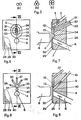
- the multi-channel injector is immersed in a measuring chamber 2.
- the measuring chamber 2 is supplied with particle-free liquid via the channel 3.
- a measuring opening 4 through which the particle-free liquid can flow.
- the electrodes 5 and 7 are located on both sides of the measuring opening 4.
- the channel 6 is embedded in the underside of the measuring chamber 2 and covered with the transparent cover 8, so that the measuring opening 4 is observed with the aid of a lens 9 and fluorescence according to the incident light principle or scattered light (Reverse control) can be measured.
- particle-free liquid flows through the measuring opening 4.
- the flow tapers in front of the measuring opening 4, so that the particle suspension resulting from the Outlet opening 13 of the multi-channel injector 1 exits into the area in front of the measuring opening 4 and is "focused" towards the measuring opening.
- the particle-free liquid is now an electrolyte, the result is when a particle passes through the measuring opening 4, a change in the resistance between the electrodes 5, 7 and thus with an impressed current the voltage peak, the height of which is a measure of the volume of the particle that has passed through.
- the multi-channel injector 1 is formed by two channels 10 and 11 which are parallel to one another.
- the cross section of the channels 10, 11 can be circular (see FIG. 5 (a), semicircular, oval, etc.) depending on the type of production.
- the production can be carried out, for example, in such a way that two glass tubes are fused together will.
- the channels 10, 11 open at the lower end into a space 12 assigned to them, which is located in front of the outlet opening 13 when measured in the flow direction.
- the channel 10 is connected to a line 14 which dips into a container 15 which contains the sample suspension, ie the particles which are to be measured as they pass through the measuring opening 4, in suspension.
- the particles are suspended in a carrier medium, for example a liquid.
- the container 15 stands on a platform 16 which is adjustable in height on the frame 17.
- the channel 11 is connected via a line 18 to a valve 19, on the other side of which a vacuum source 20 is connected.
- valve 19 If the valve 19 is opened, the vacuum generated by the vacuum source 20 draws in particle suspension via line 18, channel 11, room 12, channel 10, line 14 from the container 15. Depending on the level of the negative pressure (e.g. 0.1-0.2 bar), this can be done very quickly.
- the particle suspension reaches the lower part of the multi-channel injector 1.
- valve 19 is closed, then the platform 16 is adjusted in height such that the pressure of the particle suspension in the multi-channel injector is greater than the pressure of the particle-free liquid in the measuring chamber 2 is. Then particle suspension emerges from the space 12 via the outlet opening 13 into the area in front of the measuring opening 4, where it is caught by the particle-free solution and passed through the measuring opening 4.
- the container 15 with the particle suspension is removed and replaced by a container with rinsing liquid.
- the line 14 is immersed in the rinsing liquid.
- the valve 19 is opened again for a sufficient time so that the flushing liquid is drawn through line 14, channel 10, space 12, channel 11, line 18 and thus the line system, including the outlet opening 13 of the multi-channel injector 1, is cleaned.
- the rinsing process can be completed in a relatively short time because the above Channel system does not contain strong throttling, so that the vacuum is able to generate a strong flushing flow. Particle-free liquid is even sucked in from the measuring chamber 2 into the space 12 through the outlet opening 13, ie, in the “backward direction” with respect to the flow during the measurement. After a short time, the system is then ready to measure the next sample.
- FIG. 3 differs from that of FIGS. 1 and 2 by a further level of automation.
- the line 18 is connected to the vacuum source 20 via the valve 19.
- the line 14 is connected via a further valve 21 to a container 25 which is filled with particle-free liquid.
- a suction / pressure pump 22 which operates as a suction or pressure system with a small volume and which, in the simplest case, e.g. is designed as a motor-operated syringe for particle metering.
- the multiple injector 1 and the lines 14, 18 adjoining the channels 10, 11 are now, in deviation from FIGS. 1 and 2, arranged on a swivel arm 23 which, as indicated by the arrow 24, is movable up and down, and, after the upward movement about the axis A is pivotable.
- the pivoting can take place after the swivel arm 23 has been raised so far has been that the multi-channel injector 1 is no longer immersed in the measuring chamber 2.
- the pivoting takes place until the multi-channel injector 1 stands above a container 26 with particle suspension.
- the swivel arm 23 is moved down again until the multi-channel injector dips into the container 26.
- the measuring process begins, in which (valves 19, 21 are closed) the suction / pressure pump 22 acts as a suction pump and "backwards", that is to say via the outlet opening 13, a specific, precisely defined measuring volume of the particle suspension in milliliters. or microliter range in space 12 and 10.
- the suction process thus takes place at the tip of the multi-channel injector 1.
- the swivel arm 23 is raised, swiveled and lowered again into the measuring chamber 2.
- the suction /. Pressure pump 22 is reversed, now works as a pressure pump and presses the previously aspirated measuring volume of the particle suspension through the outlet opening 13 into the area in front of the measuring opening 4 of the measuring chamber. The measurement takes place.
- the two valves 19 and 21 are opened.
- the negative pressure of the vacuum source 20 then sucks particle-free liquid from the container 25 through the line 14, channel 10, space 12 with outlet opening 13, channel 11, line 18 and thus causes a intensive cleaning of this entire pipe system.
- the suction / pressure pump 22 goes into its rest position, in which it is used for the next measurement process is ready.
- a significant advantage of the embodiment of the invention according to FIGS. 3 and 4 compared to the embodiment according to FIGS. 1 and 2 is that only a very much smaller part of the entire pipe and tube system comes into contact with the particle suspension and therefore through it can become contaminated. The cleaning is correspondingly faster.
- the swivel arm 23 swings again over the container 26, where it can hold the next sample. The valves 19 and 21 are closed again.
- FIG. 5 shows under (a), (b) and (c) possible cross sections of multichannel injectors, the cross section shown at (a) being that of a two-channel multichannel injector as described in the exemplary embodiments according to FIGS. 1 and 2 and 3 and 4 was based.
- a three-channel, at (c) a four-channel multi-channel injector is shown.
- All channels which can be fed from different entry points via corresponding lines, each open into a room assigned to them together (corresponding to room 12 according to FIG. 2), from which an outlet opening leads into the area in front of the measuring opening or measuring zone of the measuring chamber.
- the geometry of this room is to be designed in such a way that no niches and corners in the Inside arise that hinder a quick flush.
- the essential structures of the rooms and lines in the important area i.e. in the area of the union of the various channels and the particle suspension in the flow of the particle-free electrolyte (for hydrodynamic focusing), as well as the measuring opening or zone, are incorporated into a flat surface made of glass or plastic (e.g. plexiglass), i.e. milled or etched.
- the surface with the incorporated lines and channels is then covered by a glass plate, which is pressed on by a frame or glued on with a suitable adhesive.
- the flat structure has the main advantage that all cables can be seen from the outside. This provides ideal conditions for optical measurements. You can get into the immediate vicinity of the flowing particles with lenses.
- Planar technology also offers the manufacturing advantage because the fine structures of the lines and chambers can be worked in on one level by milling, sawing, drilling or etching.
- Figures 6 and 7 show a block 28 made of plexiglass, in the surface 29 of which the lines and chambers are incorporated.
- the surface 29 is covered with a glass plate 30.
- the canals 31, 32 and 33 run obliquely through the block 28 (see FIG. 7) and open shortly before the surface 29 in the room 12.
- This room 12 is connected via the outlet opening 13 to an annular channel 34 which connects the mouth of the Surrounds channels 31, 32, 33 in the space 12 (see Fig. 6) and is connected to the channel 3 for the supply of particle-free liquid.
- the particle-free disturbance thus runs from the channel 3 into the ring channel 34.
- the particle suspension then enters the ring channel 34 from the space 12 through the outlet opening 13, the outlet opening 13 being delimited on one side by the glass plate 30.
- the measuring opening 4 is designed as a narrow passage point between the ring channel 34 and the discharge channel 6.
- the ring channel ensures a symmetrical outflow and focusing of the particle suspension emerging from the outlet opening 13.
- the area of the ring channel 34 between the outlet opening 13 and the measuring opening 4 is also the area in front of the measuring opening in which the hydrodynamically focusing flow of the particle-free liquid occurs.
- the measuring opening may lose its unambiguous character here as an opening of a container and becomes a measuring zone in which, generally speaking, observations and measurements can be made on the particles passing through. It is always defined by the fact that in it the hydrodynamic focusing a clear path control is given by refining the particle stream thread.
- channels 35, 36, 37, 38, 39 are incorporated obliquely into the block 28 and run in a star shape in the area 29 towards the space 12 in which they meet.
- This space 12 is then connected to the area 10 via the outlet opening 13.
- the channel 10 also opens there with particle-free liquid. It strikes the glass pane 30 at an angle, so that no flow component "backwards" into the space 12 occurs, but rather the particle-free liquid passes through the measuring opening 4 directly into the drainage channel 6, the particle suspension being carried along and flowing hydrodynamically when it flows past the outlet opening 13 becomes.
Landscapes
- Chemical & Material Sciences (AREA)
- Dispersion Chemistry (AREA)
- Physics & Mathematics (AREA)
- Health & Medical Sciences (AREA)
- Life Sciences & Earth Sciences (AREA)
- Analytical Chemistry (AREA)
- Biochemistry (AREA)
- General Health & Medical Sciences (AREA)
- General Physics & Mathematics (AREA)
- Immunology (AREA)
- Pathology (AREA)
- Sampling And Sample Adjustment (AREA)
- Optical Measuring Cells (AREA)
- Feeding, Discharge, Calcimining, Fusing, And Gas-Generation Devices (AREA)
- Investigating Or Analysing Biological Materials (AREA)
Applications Claiming Priority (2)
| Application Number | Priority Date | Filing Date | Title |
|---|---|---|---|
| DE19843420018 DE3420018A1 (de) | 1984-05-29 | 1984-05-29 | Vorrichtung zur messung bestimmter eigenschaften in einem traegermedium suspendierter partikel |
| DE3420018 | 1984-05-29 |
Publications (2)
| Publication Number | Publication Date |
|---|---|
| EP0163206A2 true EP0163206A2 (fr) | 1985-12-04 |
| EP0163206A3 EP0163206A3 (fr) | 1987-05-13 |
Family
ID=6237125
Family Applications (1)
| Application Number | Title | Priority Date | Filing Date |
|---|---|---|---|
| EP85106015A Withdrawn EP0163206A3 (fr) | 1984-05-29 | 1985-05-15 | Dispositif pour la mesure de propriétés données de particules en suspension dans un milieu porteur |
Country Status (3)
| Country | Link |
|---|---|
| EP (1) | EP0163206A3 (fr) |
| JP (1) | JPS6140541A (fr) |
| DE (1) | DE3420018A1 (fr) |
Cited By (4)
| Publication number | Priority date | Publication date | Assignee | Title |
|---|---|---|---|---|
| EP0333560A1 (fr) * | 1988-03-08 | 1989-09-20 | Chemunex | Procédé de détermination quantitative de micro-organismes |
| EP0286088A3 (en) * | 1987-04-08 | 1990-05-30 | Hitachi, Ltd. | A sheath flow type flow-cell device |
| EP0508688A3 (en) * | 1991-04-05 | 1993-05-19 | Toa Medical Electronics Co., Ltd. | Method and apparatus for analysing particles |
| EP0288029B1 (fr) * | 1987-04-20 | 1994-01-12 | Hitachi, Ltd. | Système de cellule à circulation de fluide |
Families Citing this family (1)
| Publication number | Priority date | Publication date | Assignee | Title |
|---|---|---|---|---|
| DE102008029700A1 (de) * | 2008-06-24 | 2010-01-14 | Palas Gmbh Partikel- Und Lasermesstechnik | Verfahren zum Bestimmen des Eindringens von Prüfpartikeln in einen Messbereich |
Family Cites Families (6)
| Publication number | Priority date | Publication date | Assignee | Title |
|---|---|---|---|---|
| US3793587A (en) * | 1971-03-10 | 1974-02-19 | Licentia Gmbh | Particle volume and cross-section measurement |
| DE2656654C3 (de) * | 1976-12-14 | 1981-02-12 | Max-Planck-Gesellschaft Zur Foerderung Der Wissenschaftense.V., 3400 Goettingen | Vorrichtung zur Messung des Volumens und bestimmter optischer Eigenschaften von Partikeln |
| DE2709399C3 (de) * | 1977-03-04 | 1980-07-24 | Goehde, Wolfgang, Dr., 4400 Muenster | Einrichtung zum Messen von Zelleigenschaften |
| DE2750447C2 (de) * | 1977-11-11 | 1986-04-17 | Max-Planck-Gesellschaft zur Förderung der Wissenschaften e.V., 3400 Göttingen | Vorrichtung zur Messung bestimmter Eigenschaften in einer Partikelsuspension suspendierter Partikel |
| US4259289A (en) * | 1979-10-22 | 1981-03-31 | Bio-Rad Laboratories, Inc. | Apparatus for retrieving liquid samples from test tubes |
| DE2943116C2 (de) * | 1979-10-25 | 1986-06-19 | Gesellschaft für Strahlen- und Umweltforschung mbH, 8000 München | Einrichtung zur durchflußcytometrischen Reaktions- und/oder Diffusionsmessung |
-
1984
- 1984-05-29 DE DE19843420018 patent/DE3420018A1/de not_active Withdrawn
-
1985
- 1985-05-15 EP EP85106015A patent/EP0163206A3/fr not_active Withdrawn
- 1985-05-28 JP JP11519385A patent/JPS6140541A/ja active Pending
Cited By (6)
| Publication number | Priority date | Publication date | Assignee | Title |
|---|---|---|---|---|
| EP0286088A3 (en) * | 1987-04-08 | 1990-05-30 | Hitachi, Ltd. | A sheath flow type flow-cell device |
| US4983038A (en) * | 1987-04-08 | 1991-01-08 | Hitachi, Ltd. | Sheath flow type flow-cell device |
| EP0288029B1 (fr) * | 1987-04-20 | 1994-01-12 | Hitachi, Ltd. | Système de cellule à circulation de fluide |
| EP0333560A1 (fr) * | 1988-03-08 | 1989-09-20 | Chemunex | Procédé de détermination quantitative de micro-organismes |
| WO1989008714A1 (fr) * | 1988-03-08 | 1989-09-21 | Chemunex | Procede de recherche, qualitatif ou quantitatif de micro-organismes, installation pour la mise en oeuvre dudit procede |
| EP0508688A3 (en) * | 1991-04-05 | 1993-05-19 | Toa Medical Electronics Co., Ltd. | Method and apparatus for analysing particles |
Also Published As
| Publication number | Publication date |
|---|---|
| JPS6140541A (ja) | 1986-02-26 |
| EP0163206A3 (fr) | 1987-05-13 |
| DE3420018A1 (de) | 1985-12-05 |
Similar Documents
| Publication | Publication Date | Title |
|---|---|---|
| DE69409567T2 (de) | Durchflusszellenvorrichtung | |
| DE2521236C3 (de) | Einrichtung zum Zählen und Messen von in einer Flüssigkeit suspendierten Teilchen | |
| DE3851458T2 (de) | Vorrichtung mit einer scheideförmigen Durchflusszelle. | |
| DE68918223T2 (de) | Blutfilter, Verfahren und Vorrichtung für hemorheologische Messungen. | |
| DE69932641T2 (de) | Kapillar-Arrayvorrichtung | |
| DE69530591T2 (de) | Fluiddüse und verfahren zum einführen eines fluids | |
| EP0163976A1 (fr) | Dispositif pour la détermination de l'activité ou de la concentration d'ions en solutions | |
| EP0619476A1 (fr) | Dispositif pour la détection d'un interface fluidique dans un tube de mesure transparent | |
| EP1311655A2 (fr) | Dispositif et procede pour mettre en contact electrique des cellules biologiques en suspension dans un liquide | |
| CH620519A5 (fr) | ||
| DE1801684B2 (de) | Einrichtung zum durchfuehren einer chemischen reaktion eines in der form von einzelnen konzentrationszonen in einem traeger medium vorliegenden stoffes | |
| DE2445411A1 (de) | Teilchenmessgeraet, fensterroehre und elektrolyt-speisevorrichtung fuer teilchenmessgeraete | |
| DE69115415T2 (de) | Teilchenanalysator und Druchflusszelle dafür | |
| DE2050672C3 (de) | Durchflußküvette zur mikroskopfotometrischen Messung von in einer Flüssigkeit suspendierten Teilchen | |
| EP0186755A2 (fr) | Cuve de circulation | |
| DE102012210457B4 (de) | Verfahren und Anordnung zur partiellen Markierung und anschließenden Quantifizierung von Zellen einer Zellsuspension | |
| DE68924879T2 (de) | Vereinfachte Entnahme- und Verteilungsvorrichtung für einen automatischen Blutanalysator. | |
| EP0163206A2 (fr) | Dispositif pour la mesure de propriétés données de particules en suspension dans un milieu porteur | |
| DE2853703A1 (de) | Kuevette zur mikroskopischen beobachtung und/oder optisch- elektrischen messung von in einer fluessigkeit suspendierten teilchen | |
| WO2025068372A1 (fr) | Dispositif microfluidique, dispositif de détection de biomarqueur comprenant un dispositif microfluidique, procédé de dépôt d'un échantillon d'un fluide corporel, et procédé d'analyse de biomarqueurs dans des fluides corporels | |
| DE3539922A1 (de) | Verfahren zum betrieb eines mikroskopiergeraets | |
| DE69837758T2 (de) | Verfahren und gerät zur bestimmung des gehalts einer komponente in einer fluiden probe | |
| DE102023126568A1 (de) | Mikrofluidische Vorrichtung, Proteindefektdiagnosevorrichtung mit mikrofluidischer Vorrichtung, Verfahren zum Blutprobenauftrag auf ein Sensorelement sowie Verfahren zur Analyse von Proteindefekten | |
| DE102023126571A1 (de) | Proteindefektanalysevorrichtung | |
| DE102023126570A1 (de) | Sensorelementhalter, Sensoreinheit, Einweg-Fluidführungsbaugruppe mit Sensoreinheit sowie Proteindefektdiagnosevorrichtung mit Einweg-Fluidführungsbaugruppe und Sensoreinheit |
Legal Events
| Date | Code | Title | Description |
|---|---|---|---|
| PUAI | Public reference made under article 153(3) epc to a published international application that has entered the european phase |
Free format text: ORIGINAL CODE: 0009012 |
|
| AK | Designated contracting states |
Designated state(s): AT BE CH DE FR GB IT LI LU NL SE |
|
| PUAL | Search report despatched |
Free format text: ORIGINAL CODE: 0009013 |
|
| AK | Designated contracting states |
Kind code of ref document: A3 Designated state(s): AT BE CH DE FR GB IT LI LU NL SE |
|
| STAA | Information on the status of an ep patent application or granted ep patent |
Free format text: STATUS: THE APPLICATION IS DEEMED TO BE WITHDRAWN |
|
| 18D | Application deemed to be withdrawn |
Effective date: 19871114 |
|
| RIN1 | Information on inventor provided before grant (corrected) |
Inventor name: KACHEL, VOLKER, DR.-ING. |