EP0163976A1 - Dispositif pour la détermination de l'activité ou de la concentration d'ions en solutions - Google Patents
Dispositif pour la détermination de l'activité ou de la concentration d'ions en solutions Download PDFInfo
- Publication number
- EP0163976A1 EP0163976A1 EP85105658A EP85105658A EP0163976A1 EP 0163976 A1 EP0163976 A1 EP 0163976A1 EP 85105658 A EP85105658 A EP 85105658A EP 85105658 A EP85105658 A EP 85105658A EP 0163976 A1 EP0163976 A1 EP 0163976A1
- Authority
- EP
- European Patent Office
- Prior art keywords
- line
- flow channel
- pump
- measuring device
- electrode
- Prior art date
- Legal status (The legal status is an assumption and is not a legal conclusion. Google has not performed a legal analysis and makes no representation as to the accuracy of the status listed.)
- Granted
Links
- 150000002500 ions Chemical class 0.000 title claims abstract description 15
- 230000000694 effects Effects 0.000 title claims abstract description 10
- 239000012482 calibration solution Substances 0.000 claims abstract description 41
- 239000000243 solution Substances 0.000 claims abstract description 24
- 230000002572 peristaltic effect Effects 0.000 claims abstract description 8
- 239000007788 liquid Substances 0.000 claims description 57
- 239000002699 waste material Substances 0.000 claims description 14
- 239000003792 electrolyte Substances 0.000 claims description 9
- 230000004888 barrier function Effects 0.000 claims description 8
- 238000011144 upstream manufacturing Methods 0.000 claims description 5
- 238000007789 sealing Methods 0.000 claims description 3
- 230000015572 biosynthetic process Effects 0.000 claims 1
- 239000000523 sample Substances 0.000 description 40
- 238000005259 measurement Methods 0.000 description 23
- 239000012528 membrane Substances 0.000 description 15
- 238000000034 method Methods 0.000 description 12
- 239000008280 blood Substances 0.000 description 9
- 210000004369 blood Anatomy 0.000 description 9
- 239000008151 electrolyte solution Substances 0.000 description 6
- 229940021013 electrolyte solution Drugs 0.000 description 6
- 239000011521 glass Substances 0.000 description 5
- 229920003023 plastic Polymers 0.000 description 5
- 230000008901 benefit Effects 0.000 description 4
- 239000012530 fluid Substances 0.000 description 4
- 230000008569 process Effects 0.000 description 4
- 238000005086 pumping Methods 0.000 description 4
- OKTJSMMVPCPJKN-UHFFFAOYSA-N Carbon Chemical compound [C] OKTJSMMVPCPJKN-UHFFFAOYSA-N 0.000 description 3
- 229910002804 graphite Inorganic materials 0.000 description 3
- 239000010439 graphite Substances 0.000 description 3
- 239000000463 material Substances 0.000 description 3
- 239000012086 standard solution Substances 0.000 description 3
- DGAQECJNVWCQMB-PUAWFVPOSA-M Ilexoside XXIX Chemical compound C[C@@H]1CC[C@@]2(CC[C@@]3(C(=CC[C@H]4[C@]3(CC[C@@H]5[C@@]4(CC[C@@H](C5(C)C)OS(=O)(=O)[O-])C)C)[C@@H]2[C@]1(C)O)C)C(=O)O[C@H]6[C@@H]([C@H]([C@@H]([C@H](O6)CO)O)O)O.[Na+] DGAQECJNVWCQMB-PUAWFVPOSA-M 0.000 description 2
- WCUXLLCKKVVCTQ-UHFFFAOYSA-M Potassium chloride Chemical compound [Cl-].[K+] WCUXLLCKKVVCTQ-UHFFFAOYSA-M 0.000 description 2
- 238000004140 cleaning Methods 0.000 description 2
- 238000011109 contamination Methods 0.000 description 2
- 229920002457 flexible plastic Polymers 0.000 description 2
- 238000001802 infusion Methods 0.000 description 2
- 238000002347 injection Methods 0.000 description 2
- 239000007924 injection Substances 0.000 description 2
- 239000000203 mixture Substances 0.000 description 2
- 238000012544 monitoring process Methods 0.000 description 2
- 229920001296 polysiloxane Polymers 0.000 description 2
- 230000010349 pulsation Effects 0.000 description 2
- 238000009736 wetting Methods 0.000 description 2
- 241000881711 Acipenser sturio Species 0.000 description 1
- ZLMJMSJWJFRBEC-UHFFFAOYSA-N Potassium Chemical compound [K] ZLMJMSJWJFRBEC-UHFFFAOYSA-N 0.000 description 1
- 229910021607 Silver chloride Inorganic materials 0.000 description 1
- 108010067973 Valinomycin Proteins 0.000 description 1
- 230000009471 action Effects 0.000 description 1
- XAGFODPZIPBFFR-UHFFFAOYSA-N aluminium Chemical compound [Al] XAGFODPZIPBFFR-UHFFFAOYSA-N 0.000 description 1
- 229910052782 aluminium Inorganic materials 0.000 description 1
- 239000007864 aqueous solution Substances 0.000 description 1
- FCFNRCROJUBPLU-UHFFFAOYSA-N compound M126 Natural products CC(C)C1NC(=O)C(C)OC(=O)C(C(C)C)NC(=O)C(C(C)C)OC(=O)C(C(C)C)NC(=O)C(C)OC(=O)C(C(C)C)NC(=O)C(C(C)C)OC(=O)C(C(C)C)NC(=O)C(C)OC(=O)C(C(C)C)NC(=O)C(C(C)C)OC1=O FCFNRCROJUBPLU-UHFFFAOYSA-N 0.000 description 1
- 238000010276 construction Methods 0.000 description 1
- 230000003247 decreasing effect Effects 0.000 description 1
- 230000002950 deficient Effects 0.000 description 1
- 238000013461 design Methods 0.000 description 1
- 238000001514 detection method Methods 0.000 description 1
- 230000006866 deterioration Effects 0.000 description 1
- 230000005684 electric field Effects 0.000 description 1
- 230000005686 electrostatic field Effects 0.000 description 1
- 230000007613 environmental effect Effects 0.000 description 1
- 238000011156 evaluation Methods 0.000 description 1
- 239000012535 impurity Substances 0.000 description 1
- 238000003780 insertion Methods 0.000 description 1
- 230000037431 insertion Effects 0.000 description 1
- 238000009434 installation Methods 0.000 description 1
- 230000002452 interceptive effect Effects 0.000 description 1
- 230000007257 malfunction Effects 0.000 description 1
- 238000000691 measurement method Methods 0.000 description 1
- 230000006911 nucleation Effects 0.000 description 1
- 238000010899 nucleation Methods 0.000 description 1
- 229910052700 potassium Inorganic materials 0.000 description 1
- 239000011591 potassium Substances 0.000 description 1
- 239000001103 potassium chloride Substances 0.000 description 1
- 235000011164 potassium chloride Nutrition 0.000 description 1
- 238000004062 sedimentation Methods 0.000 description 1
- 238000000926 separation method Methods 0.000 description 1
- 210000002966 serum Anatomy 0.000 description 1
- HKZLPVFGJNLROG-UHFFFAOYSA-M silver monochloride Chemical compound [Cl-].[Ag+] HKZLPVFGJNLROG-UHFFFAOYSA-M 0.000 description 1
- 229910052708 sodium Inorganic materials 0.000 description 1
- 239000011734 sodium Substances 0.000 description 1
- FAPWRFPIFSIZLT-UHFFFAOYSA-M sodium chloride Inorganic materials [Na+].[Cl-] FAPWRFPIFSIZLT-UHFFFAOYSA-M 0.000 description 1
- 239000011780 sodium chloride Substances 0.000 description 1
- 210000002023 somite Anatomy 0.000 description 1
- 239000000126 substance Substances 0.000 description 1
- 238000012360 testing method Methods 0.000 description 1
- 230000007704 transition Effects 0.000 description 1
- FCFNRCROJUBPLU-DNDCDFAISA-N valinomycin Chemical compound CC(C)[C@@H]1NC(=O)[C@H](C)OC(=O)[C@@H](C(C)C)NC(=O)[C@@H](C(C)C)OC(=O)[C@H](C(C)C)NC(=O)[C@H](C)OC(=O)[C@@H](C(C)C)NC(=O)[C@@H](C(C)C)OC(=O)[C@H](C(C)C)NC(=O)[C@H](C)OC(=O)[C@@H](C(C)C)NC(=O)[C@@H](C(C)C)OC1=O FCFNRCROJUBPLU-DNDCDFAISA-N 0.000 description 1
- 238000013022 venting Methods 0.000 description 1
Images

Classifications
-
- A—HUMAN NECESSITIES
- A61—MEDICAL OR VETERINARY SCIENCE; HYGIENE
- A61M—DEVICES FOR INTRODUCING MEDIA INTO, OR ONTO, THE BODY; DEVICES FOR TRANSDUCING BODY MEDIA OR FOR TAKING MEDIA FROM THE BODY; DEVICES FOR PRODUCING OR ENDING SLEEP OR STUPOR
- A61M1/00—Suction or pumping devices for medical purposes; Devices for carrying-off, for treatment of, or for carrying-over, body-liquids; Drainage systems
- A61M1/36—Other treatment of blood in a by-pass of the natural circulatory system, e.g. temperature adaptation, irradiation ; Extra-corporeal blood circuits
- A61M1/3621—Extra-corporeal blood circuits
-
- A—HUMAN NECESSITIES
- A61—MEDICAL OR VETERINARY SCIENCE; HYGIENE
- A61M—DEVICES FOR INTRODUCING MEDIA INTO, OR ONTO, THE BODY; DEVICES FOR TRANSDUCING BODY MEDIA OR FOR TAKING MEDIA FROM THE BODY; DEVICES FOR PRODUCING OR ENDING SLEEP OR STUPOR
- A61M1/00—Suction or pumping devices for medical purposes; Devices for carrying-off, for treatment of, or for carrying-over, body-liquids; Drainage systems
- A61M1/14—Dialysis systems; Artificial kidneys; Blood oxygenators ; Reciprocating systems for treatment of body fluids, e.g. single needle systems for hemofiltration or pheresis
- A61M1/16—Dialysis systems; Artificial kidneys; Blood oxygenators ; Reciprocating systems for treatment of body fluids, e.g. single needle systems for hemofiltration or pheresis with membranes
- A61M1/1601—Control or regulation
- A61M1/1603—Regulation parameters
- A61M1/1605—Physical characteristics of the dialysate fluid
- A61M1/1607—Physical characteristics of the dialysate fluid before use, i.e. upstream of dialyser
-
- A—HUMAN NECESSITIES
- A61—MEDICAL OR VETERINARY SCIENCE; HYGIENE
- A61M—DEVICES FOR INTRODUCING MEDIA INTO, OR ONTO, THE BODY; DEVICES FOR TRANSDUCING BODY MEDIA OR FOR TAKING MEDIA FROM THE BODY; DEVICES FOR PRODUCING OR ENDING SLEEP OR STUPOR
- A61M1/00—Suction or pumping devices for medical purposes; Devices for carrying-off, for treatment of, or for carrying-over, body-liquids; Drainage systems
- A61M1/14—Dialysis systems; Artificial kidneys; Blood oxygenators ; Reciprocating systems for treatment of body fluids, e.g. single needle systems for hemofiltration or pheresis
- A61M1/16—Dialysis systems; Artificial kidneys; Blood oxygenators ; Reciprocating systems for treatment of body fluids, e.g. single needle systems for hemofiltration or pheresis with membranes
- A61M1/1601—Control or regulation
- A61M1/1603—Regulation parameters
- A61M1/1605—Physical characteristics of the dialysate fluid
- A61M1/1609—Physical characteristics of the dialysate fluid after use, i.e. downstream of dialyser
-
- A—HUMAN NECESSITIES
- A61—MEDICAL OR VETERINARY SCIENCE; HYGIENE
- A61M—DEVICES FOR INTRODUCING MEDIA INTO, OR ONTO, THE BODY; DEVICES FOR TRANSDUCING BODY MEDIA OR FOR TAKING MEDIA FROM THE BODY; DEVICES FOR PRODUCING OR ENDING SLEEP OR STUPOR
- A61M1/00—Suction or pumping devices for medical purposes; Devices for carrying-off, for treatment of, or for carrying-over, body-liquids; Drainage systems
- A61M1/14—Dialysis systems; Artificial kidneys; Blood oxygenators ; Reciprocating systems for treatment of body fluids, e.g. single needle systems for hemofiltration or pheresis
- A61M1/16—Dialysis systems; Artificial kidneys; Blood oxygenators ; Reciprocating systems for treatment of body fluids, e.g. single needle systems for hemofiltration or pheresis with membranes
- A61M1/1621—Constructional aspects thereof
- A61M1/165—Constructional aspects thereof with a dialyser bypass on the dialysis fluid line
-
- A—HUMAN NECESSITIES
- A61—MEDICAL OR VETERINARY SCIENCE; HYGIENE
- A61M—DEVICES FOR INTRODUCING MEDIA INTO, OR ONTO, THE BODY; DEVICES FOR TRANSDUCING BODY MEDIA OR FOR TAKING MEDIA FROM THE BODY; DEVICES FOR PRODUCING OR ENDING SLEEP OR STUPOR
- A61M1/00—Suction or pumping devices for medical purposes; Devices for carrying-off, for treatment of, or for carrying-over, body-liquids; Drainage systems
- A61M1/36—Other treatment of blood in a by-pass of the natural circulatory system, e.g. temperature adaptation, irradiation ; Extra-corporeal blood circuits
- A61M1/3607—Regulation parameters
- A61M1/3609—Physical characteristics of the blood, e.g. haematocrit, urea
- A61M1/361—Physical characteristics of the blood, e.g. haematocrit, urea before treatment
-
- A—HUMAN NECESSITIES
- A61—MEDICAL OR VETERINARY SCIENCE; HYGIENE
- A61M—DEVICES FOR INTRODUCING MEDIA INTO, OR ONTO, THE BODY; DEVICES FOR TRANSDUCING BODY MEDIA OR FOR TAKING MEDIA FROM THE BODY; DEVICES FOR PRODUCING OR ENDING SLEEP OR STUPOR
- A61M1/00—Suction or pumping devices for medical purposes; Devices for carrying-off, for treatment of, or for carrying-over, body-liquids; Drainage systems
- A61M1/36—Other treatment of blood in a by-pass of the natural circulatory system, e.g. temperature adaptation, irradiation ; Extra-corporeal blood circuits
- A61M1/3607—Regulation parameters
- A61M1/3609—Physical characteristics of the blood, e.g. haematocrit, urea
- A61M1/3612—Physical characteristics of the blood, e.g. haematocrit, urea after treatment
-
- A—HUMAN NECESSITIES
- A61—MEDICAL OR VETERINARY SCIENCE; HYGIENE
- A61M—DEVICES FOR INTRODUCING MEDIA INTO, OR ONTO, THE BODY; DEVICES FOR TRANSDUCING BODY MEDIA OR FOR TAKING MEDIA FROM THE BODY; DEVICES FOR PRODUCING OR ENDING SLEEP OR STUPOR
- A61M2205/00—General characteristics of the apparatus
- A61M2205/33—Controlling, regulating or measuring
- A61M2205/3317—Electromagnetic, inductive or dielectric measuring means
-
- A—HUMAN NECESSITIES
- A61—MEDICAL OR VETERINARY SCIENCE; HYGIENE
- A61M—DEVICES FOR INTRODUCING MEDIA INTO, OR ONTO, THE BODY; DEVICES FOR TRANSDUCING BODY MEDIA OR FOR TAKING MEDIA FROM THE BODY; DEVICES FOR PRODUCING OR ENDING SLEEP OR STUPOR
- A61M2205/00—General characteristics of the apparatus
- A61M2205/33—Controlling, regulating or measuring
- A61M2205/3324—PH measuring means
-
- A—HUMAN NECESSITIES
- A61—MEDICAL OR VETERINARY SCIENCE; HYGIENE
- A61M—DEVICES FOR INTRODUCING MEDIA INTO, OR ONTO, THE BODY; DEVICES FOR TRANSDUCING BODY MEDIA OR FOR TAKING MEDIA FROM THE BODY; DEVICES FOR PRODUCING OR ENDING SLEEP OR STUPOR
- A61M2205/00—General characteristics of the apparatus
- A61M2205/33—Controlling, regulating or measuring
- A61M2205/3331—Pressure; Flow
- A61M2205/3358—Measuring barometric pressure, e.g. for compensation
-
- A—HUMAN NECESSITIES
- A61—MEDICAL OR VETERINARY SCIENCE; HYGIENE
- A61M—DEVICES FOR INTRODUCING MEDIA INTO, OR ONTO, THE BODY; DEVICES FOR TRANSDUCING BODY MEDIA OR FOR TAKING MEDIA FROM THE BODY; DEVICES FOR PRODUCING OR ENDING SLEEP OR STUPOR
- A61M2205/00—General characteristics of the apparatus
- A61M2205/33—Controlling, regulating or measuring
- A61M2205/3368—Temperature
- A61M2205/3372—Temperature compensation
-
- A—HUMAN NECESSITIES
- A61—MEDICAL OR VETERINARY SCIENCE; HYGIENE
- A61M—DEVICES FOR INTRODUCING MEDIA INTO, OR ONTO, THE BODY; DEVICES FOR TRANSDUCING BODY MEDIA OR FOR TAKING MEDIA FROM THE BODY; DEVICES FOR PRODUCING OR ENDING SLEEP OR STUPOR
- A61M2205/00—General characteristics of the apparatus
- A61M2205/50—General characteristics of the apparatus with microprocessors or computers
-
- Y—GENERAL TAGGING OF NEW TECHNOLOGICAL DEVELOPMENTS; GENERAL TAGGING OF CROSS-SECTIONAL TECHNOLOGIES SPANNING OVER SEVERAL SECTIONS OF THE IPC; TECHNICAL SUBJECTS COVERED BY FORMER USPC CROSS-REFERENCE ART COLLECTIONS [XRACs] AND DIGESTS
- Y10—TECHNICAL SUBJECTS COVERED BY FORMER USPC
- Y10T—TECHNICAL SUBJECTS COVERED BY FORMER US CLASSIFICATION
- Y10T436/00—Chemistry: analytical and immunological testing
- Y10T436/25—Chemistry: analytical and immunological testing including sample preparation
- Y10T436/25375—Liberation or purification of sample or separation of material from a sample [e.g., filtering, centrifuging, etc.]
- Y10T436/255—Liberation or purification of sample or separation of material from a sample [e.g., filtering, centrifuging, etc.] including use of a solid sorbent, semipermeable membrane, or liquid extraction
Definitions
- the invention relates to a measuring device for determining the activity or the concentration of ions in solutions, with at least one measuring electrode and a reference electrode, which are connected to one another by a flow channel, the first output of which is connected to the environment and the second output of which is connected by a first line , in which a first pump and at least one valve is switched on, is connected to at least one calibration solution container.
- a measuring device of the type mentioned is known for example from US Pat. Nos. 42 06 0227, 31 51 052 and 35 56 950 and from the monograph by Karl Cammann, "Working with ion-selective electrodes", Springer-Verlag 1977, 5,190-194 .
- Each of these devices consists of a plurality of electrodes which are arranged one against the other and are connected to one another by a flow channel. They thus form a flow arrangement on the one One side via a line with containers, which have one or more standard solutions and a measuring solution, and on the other side is connected to a pump.
- a multi-way valve is provided in the connecting line to the flow arrangement, which valve is opened or closed accordingly by a control device.
- Such a flow arrangement can have a plurality of different electrodes, for example ion-selective electrodes, which regularly have a reference electrode as a reference point for measuring a particular type of ion, for example the sodium or potassium order.
- ion-selective electrodes which regularly have a reference electrode as a reference point for measuring a particular type of ion, for example the sodium or potassium order.
- a first standard solution is connected to the supply line via the multi-way valve and then pumped into the flow arrangement by the pump and then the entire system is calibrated.
- the pump is provided upstream of the flow device in the feed line, while the sample connection is located downstream of the flow arrangement.
- the calibration solutions are conveyed into the flow arrangement by clockwise rotation of the pump, while the sample is drawn into the flow arrangement by counterclockwise rotation and is conveyed from there through the pump into the waste.
- a multi-way valve or a branching of a plurality of lines, into which one valve is switched on, is provided upstream of the pump.
- This arrangement also has the disadvantage that, after the sample has been sucked off, residues of the sample remain in the connecting line between the flow arrangement and the multiple valve, which leads to a mixing of the calibration liquid with the sample residues in the hose and in the multiple valve when the first calibration solution is supplied.
- the multiple valve or the distributor is permanently contaminated by residues of the sample liquid, for example blood, since the blood settles.
- the invention is therefore based on the object of developing the measuring device of the type mentioned at the outset in such a way that the smallest possible quantities of standard and measuring solution are necessary for an accurate measurement with the shortest possible time.
- the measuring device initially has the advantage that the mixing areas, i.e. the areas in which the calibration solutions and the measurement solution are inevitably mixed are kept as small as possible.
- the feed line for the calibration solutions has a branching line adjacent to the input of the measuring device, which line is used to discharge the measured liquid (calibration solution or measuring solution). As a result, the entire supply line no longer comes into contact with the solution to be measured.
- the area through which all liquids have to flow thus remains essentially restricted to the flow channel of the measuring arrangement itself.
- a pump is provided in the branch line, with which the liquid to be pumped is conveyed through the measuring device and the branch line.
- This pump should have at least the same capacity as the pump arranged in the feed line.
- a single pump is used in the form of a peristaltic roller pump, which acts on both sides, i.e. both the feed line and the discharge line are each inserted into a pump segment of the roller hose pump.
- the same or variable delivery volumes can be determined.
- the feed hose has a smaller inner diameter than the discharge hose, i.e. the delivery volume of the discharge hose is larger than that of the feed hose.
- the double-acting pump pumps the calibration solution up to the branch point.
- the supplied calibration solution is pumped out through the branch line, so that the calibration solution is thereby pumped past the flow arrangement into the drain.
- This method of pumping continues until any coarse impurities present in the feed branch have been removed.
- a valve arranged downstream of the pump segment in the drain branch is closed, with the result that this pump segment no longer delivers.
- the pure calibration solution is inevitably pumped into the flow-through arrangement, since this further conveys a pump segment in the feed line.
- the calibration solution is delivered until the flow channel in the measuring device is completely filled.
- the valve which is arranged at the outlet of the container with the calibration solution, is then closed.
- the roller hose pump advantageously remains in operation and generated after this valve is closed due to the constant occlusion of the hose, a pulsation of the liquid column in the hose and in the flow arrangement.
- all remaining coarse contaminations that is to say also those sample components which got stuck on the wall of the flow channel, are absorbed by the calibration solution and distributed therein.
- valve in the drain line is now opened again, a negative pressure is generated in the entire flow arrangement, with the result that the liquid column located in the entire flow channel is conveyed into the drain.
- the valves provided in the supply line are closed.
- the drain valve is then closed and the valve located downstream of the container with the calibration solution is opened again, as a result of which pure calibration solution flows into the flow channel again.
- this step there is pure calibration solution in the flow arrangement within the measuring limits, so that the calibration of this flow arrangement can now take place.
- the measured value is determined. This is followed by a new measuring cycle, consisting of introducing the measuring solution into the measuring device and calibration.
- the measurement solution is supplied from the other opening of the supply channel through a capillary, the pump continuing to be operated on the side of the drain line in which the valve located there is open. After the channel has been filled, the parameters are measured using the electrodes and the downstream evaluation unit.
- a further line is provided on the supply side of the calibration solutions, in which a valve is also switched on. Air can be supplied through this line and this air supply has the advantage that only a certain amount of liquid can be pumped through the supply line at any time without the liquid column being conveyed coming to a standstill as a result of negative pressure when the valve, which is assigned to the respective calibration solution container, is shut off is coming.
- the liquids are conveyed through the flow channel only in one direction.
- the one end of the flow channel of the measuring device according to the invention is connected to a feed line, from each of which branches branch off, which are connected to calibration solution containers or to the environment (air).
- These branch lines can be shut off by appropriate valves. Downstream of these valves, a pump is in turn connected into this line, via which the fluids to be conveyed are conveyed into the measuring channel.
- the discharge line opens into a collecting vessel, so that the pressure fluctuations in the channel are reduced.
- This collecting vessel is connected to a drain line into which a pump is switched on.
- This pump is advantageously in Ver bond with the pump in the feed line combined to form a double-acting pump, as explained above in the first embodiment.
- the measurement solution is supplied on the side of the supply line directly into the measurement channel in that a cannula is pierced through a septum arranged in front of the measurement channel and inserted into the measurement channel.
- This arrangement is particularly advantageous when taking blood using a syringe, which can then be inserted directly into the measuring channel.
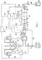
- FIG. 1 shows a measuring device 20 which represents the first preferred embodiment of the invention.
- This measuring device 20 has an electrode block 22, which in Example 2 is composed of four individual electrodes. Such an electrode block is explained below as shown in FIG. 4.
- a flow channel 24 is penetrated through this electrode block 22, all electrodes each having a part of this flow channel. When assembling the electrodes, these parts are aligned with axial alignment and thus form the flow channel 24.
- the flow channel 24 has two end regions 26 and 28 in the electrode block, which are each connected to branching lines 30 and 32.
- the line 30 thus extends away from the end region 26 and leads through a pump 34, which is advantageously designed as a peristaltic roller hose pump, wherein it is inserted into a segment, as shown in FIG. 1.
- a pump 34 which is advantageously designed as a peristaltic roller hose pump, wherein it is inserted into a segment, as shown in FIG. 1.
- line 30 Upstream of the pump, line 30 has a branching or mixing point 36, several of which Branch lines, namely lines 38, 40 and 42.
- a shut-off device 44, 46 and 48 is switched into each of these lines 38-42.
- line 38 is connected to a vessel 50 for a first calibration solution, while line 42 is connected to a vessel 52 with a second calibration solution.
- the line 40 represents an air connection and is therefore connected to the environment in a pressure-balanced manner.
- a drain line 54 branches off from the line 30 at the branching point 56.
- This line 54 is also inserted like the line 30 into the pump 34, so that here again a pump segment of the pump 34 can act on the line 54.
- the pump 34 which is advantageously designed as a peristaltic hose pump, acts on both sides.
- this double-sided pump 34 can also be replaced by two pumps, each acting on the lines 30 and 54, respectively.
- line 54 permits at least the same delivery volume as line 30.
- the delivery volume of line 54 is greater than that of line 30, i.e. the internal cross section of line 54 is larger than that of line 30.
- the delivery volume of separate pumps is designed such that the pump connected to line 54 has at least the same delivery volume as the pump used in line 30. The delivery volume of both pumps is preferably the same.
- a valve 58 is switched on in line 54 downstream of the pump 34.
- the line end 60 of the line 54 opens into a waste container 62, which is used to hold the used liquids.
- the other end region 28 of the electrode block 22 is connected via a line 32 to an adapter 64, which is designed in such a way that it can receive an exchangeable aspiration cannula 66.
- Both the line 32 and the aspiration cannula 66 are preferably designed to be flexible, so that this entire arrangement can be arranged in any manner.
- the aspiration cannula 66 is expediently used in the form of a flexible plastic tube, which can be replaced again after a single use.
- the cannula of a syringe can also be inserted into the adapter 64, which was used, for example, for taking blood.
- the aspiration cannula 66 can be immersed in a container 68 which contains the liquid to be subjected to the measurement.
- the lines 30 and 32 Adjacent to the end regions 26 and 28, the lines 30 and 32 each have sensors 70 and 72, with which the liquid columns arriving through the lines 30 and 32 can be reliably identified and monitored in their positioning. IR light barriers are advantageously used as sensors 70 and 72.
- Another such sensor 76 is arranged in the line 30 between the pump 34 and the branch point 56. Finally, there is a sensor 76 in the Area of line 54 between valve 58 and line end 60.
- the latter sensors are also advantageously designed as IR light barriers.
- the sensors 70 and 72 control the correct filling of the measuring capillaries, the aspiration cartridge, the line 32, the flow channel 24 and the line 30.
- the sensor 74 serves as a monitor for the supply of the calibration solutions from the containers 50 and 52 or the air.
- the sensor 76 advantageously controls the drain line 54 and checks whether the waste container 62 is filled by pumping the pump backwards, that is to say by changing the direction of rotation of the pump.
- the line end 60 of the line 54 is arranged only briefly below the upper edge of the waste container 62. If waste liquid reaches this line end 60, there is a signal at sensor 76 when a corresponding liquid column is pulled up.
- valves 44, 46, 48 and 58 are connected via lines 78-84 to a valve control device 86 which is connected to a general control device 90 via a line 88.
- the electrodes of the electrode block 22 are connected via lines 92 to an electrode connection device 94 which is also connected to the control device 90 via a line 96.
- sensors 70, 72, 74 and 76 are connected via lines 98-102 to a sensor control device 104 which is connected to the control device 90 via the line 106.
- control device 90 is connected to the motor 34 via the line 108.
- devices 86, 90, 94 and 104 can also be integrated into a single device, which is advantageously the case.
- valves 44-48 or 58 are opened or closed by the control device 90 via the valve control device 86.
- This control device also receives the signal from the sensor display device 104 and evaluates it in a corresponding manner, the valve control device 86 or the motor 34 being controlled accordingly via the line 108.
- control unit 90 also receives the signals from the electrode connection device 94, which converts and evaluates the electrode signals.
- the sample is sucked out of the container 68 with the help of the pump 34 with the valve 58 open up to the branch 54, the sensors 70 and 72 monitor the correct filling of the flow channel 24.
- the pump is operated for a certain time interval to ensure that residues of the calibration solutions in the flow channel 24 are completely removed from the measuring range into the waste line.
- the sample is advantageously transported further by the length of the aspiration cannula 66. This frees the aspiration cannula 66 and prevents the sample from dripping.
- the first part of the sample which is particularly contaminated by the residual liquid in the measuring capillary or the flow channel 24 is pushed out of the electrode block 22 and the carryover of the sample is thus reduced without increasing the amount of sample.
- the desired parameters are then measured, the pump 34 being stopped by the control device 90 for this purpose.
- the pump 34 is operated with the valve 58 open until the sample has been completely pumped through the drain line 54 into the waste container 62.
- a one-point calibration can also be carried out, provided that the error that occurs as a result can be estimated.
- the recalibration required in the previous method after a certain time or number of measurements and the possibility of increasing errors in omitting this measure are eliminated. It only presupposes the same temperature of the sample and calibration liquids, which can usually be guaranteed since the measuring device 20 is usually at the ambient temperature and has a significantly greater heat capacity than the sample (typically a few 100 ⁇ l). For example, a blood sample of 37 ° C takes on the ambient temperature within seconds.
- the conductivity and the ionic activity coefficients also have a clear temperature dependence. These variables are usually measured at an ambient temperature to be determined and converted numerically or in terms of circuitry to the value of 25 ° C.
- the geometry of the LF measuring cell is also not included in this relative method.
- the valve 44 is opened so that the first calibration liquid is pumped further through line 38 into line 30 to branching point 56 and from there through the negative pressure generated in the other pump segment into line 54.
- the line 30 is cleaned of residues of the previously remaining calibration liquid.
- the valve 58 in the drain line 54 is closed, which causes the calibration solution to enter the flow channel 24.
- the effect of the pump is only interrupted when the liquid column of the first calibration liquid has been pumped through the entire flow channel 24 and has reached the sensor 72, which emits a corresponding signal for closing the valve 44 to the control unit 90.
- the pump 34 continues to pump and, due to its peristaltic character, induces a pulsation in the hose line, so that the entire liquid column also intensively wets the surfaces on which there are usually test residues. At this point, the electrodes continue to settle into the new solution.
- valve 58 in the drain line is opened again, so that the amount of liquid in the flow channel 24 is sucked off again.
- the valve 58 is then closed and the valve 44 is opened again in order to introduce fresh calibration solution into the flow channel 24 again.
- the stop signal by the sensor 72 the actual measurement is then carried out by the electrodes of the electrode block 22.
- the method described for the first calibration liquid is also applied identically to the second calibration liquid.
- the intermediate rinsing brings the electrodes into contact with the solution to be measured before the measurement. This increases the time available for the electrodes to adjust to the new measuring solution or reduces the need for measuring time.
- the values determined during calibration are compared with the values that were previously stored in the electrode connection device 94 and, if necessary, related to these values. This is followed by the actual measurement of the sample, which is then followed by a two-point calibration.
- the flexible plastic cannula held in a silicone tube (line 32) or the adapter 64 is exchanged. This means that this cannula does not contribute to the carryover of samples, which is the case with a fixed cannula.
- the entire line 30 is preferably not filled with calibration liquid.
- the valves 44 and 48 are only opened until the amount of liquid required to fill the flow channel 24 has been drawn off from the container 50 or 52. Then valves 44 and 48 are closed and valve 46 is opened so that air can enter, i.e. no negative pressure can occur in line 30, which would otherwise retain the liquid column in line 30. This valve 46 is then closed when the liquid column has reached the sensor 72. Otherwise, the further procedure is the same as the procedure described above.
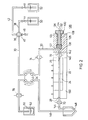
- FIG. 2 shows a measuring device 120 which represents the second embodiment of the measuring device according to the invention.
- the same reference numerals as in FIG. 1 have been used for the same parts.
- the measuring device 120 in turn has an electrode block 22 which is penetrated by a flow channel 24.
- the flow channel is in turn connected to the supply line 30 into which the sensor 74, a segment of the pump 34, the mixing point 36, the lines 38, 40 and 42, the valves 44, 46 and 48 and the containers 50 and 52 are switched on .
- the line 30 does not open directly into the end region 26 of the flow channel 24, but rather is connected to a channel 122, the axis of which is essentially perpendicular to the axis of the flow channel 24 and which is in flow connection with this flow channel 24.
- This channel 122 is arranged in a septum adapter 124, which has a septum 126 made of rubber or a plastic that can be pierced with a cannula tip.
- the septum is arranged in a corresponding bore 128 in the septum adapter, the inner surface of which is partially covered with a Ge winch 130 is provided.
- a plug 132 which is provided with a corresponding thread 134 and which fixes the septum in position, can be screwed into this thread.
- This plug 132 has a central channel 136 which is aligned with the flow channel 24 and whose diameter corresponds approximately to the diameter of the flow channel.
- This channel 136 serves as an insertion aid for an injection needle or the tip of a cannula which is inserted into the channel 24 through the septum.
- the syringe adapter is further provided with a channel piece 138 which branches off from the channel 122 at a right angle and is aligned with the flow channel 24.
- a sensor housing 140 is arranged between the electrode block 22 and the septum adapter 124, which receives the sensor 70 and is also penetrated by a channel piece 142, which in turn is aligned with the flow channel 24.
- the other output or end region 28 is connected to a line 144 which is provided with the sensor 72.
- This line 144 opens into a pressure equalization vessel 146, which advantageously tapers in the bottom area.
- the suction line 148 is led to the bottom, which is inserted into the other segment of the pump 34 and, like the line 54 according to FIG. 1, ends in the waste container 62. Furthermore, a sensor 76 is arranged in this suction line 148, which in the example is arranged downstream of the pump 34 in accordance with the embodiment shown in FIG. 1.
- the line 144 advantageously ends adjacent the end region 28 of the electrode block 22 under pressure equalization, this end region advantageously at the reference electrode 150 of the electrode blocks 22 is formed.
- Such an arrangement is advantageous because pressure fluctuations at the reference electrode 150 are to be kept as low as possible.
- the surge tank 146 is in close proximity to the reference electrode 150 and the end of the hose 144 is at atmospheric pressure. In this respect, there are only slight pressure fluctuations around this value on the membrane of the reference electrode 150, so that an infusion into the reference electrode and thus potential jumps and the like. be prevented.
- Such an infusion would have been feared by the overpressure in the electrolyte line, which arises from the pushing of liquid segments through the line. This increases with the length of the line and the number of liquid segments in the line. According to the invention, a drift of the reference electrode due to this is avoided by the arrangement of a pressure compensation vessel 146.
- the hose size of the line 148 is dimensioned such that the delivery line in the waste line 148 is larger than in the line 144 or the flow channel 24. This prevents the surge tank 146 from being overfilled.
- This advantageously consists of a plastic material and is designed as a disposable so that it can be replaced in the event of malfunctions. Furthermore, there is no sedimentation or nucleation in the pressure compensation container 146 for at least one month if the waste line 148 is led into the tip of the container 146 with a rigid plastic capillary.
- valve 58 according to FIG. 2 is missing in the waste line 148. Fig. 1.
- the pump 34 is started again and the air valve 46 is opened so that the sample is pumped into the surge tank 146 and from there into the waste tank 62.
- a larger liquid segment from one of the two containers 50, 52 is introduced for the measurement by corresponding opening of the valves 44 and 48 and positioned so that the two sensors 70 and 72 - as explained below - report solutions, so give a corresponding signal.
- sensors 70-76 are used for the reliable detection and positioning of the liquid columns in the measuring devices 20 and 120, which sensors are advantageously designed as IR light barriers.
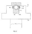
- 3 shows a section through the sensor 74 according to FIG. 1 along the line III-III.
- This sensor 74 essentially consists of a photodiode 160, which is arranged opposite a phototransistor 162. Both the photodiode 160 and the phototransistor 162 are arranged in a light barrier housing 164, which has a recess 166, in which a two-part hose guide 168 is arranged. The side walls of the recess 166 receive the photodiode 160 and the phototransistor 162.
- the hose guide has a bore 170 for receiving the hose 172, which corresponds to the line 30.
- the hose guide 168 and the hose 172 are transparent to IR light, so that permanent monitoring is ensured.
- the light barriers have an almost punctiform transmitter and receiver.
- a transparent silicone tube or a glass capillary By suitably inserting a transparent silicone tube or a glass capillary into the beam path, as shown in FIG. 3, clearly different output signals for blood, an aqueous electrolyte solution or air are obtained.
- a large part of the light is absorbed in blood.
- the capillary (tube) acts like a cylindrical lens and focuses the light on the receptor.
- This is designed as a phototransistor and is therefore only weakly activated for blood, strongly for aqueous solutions and in the middle in the case of air. This property can be used to differentiate between the samples and to activate special measuring programs for whole blood on the one hand and serum, plasma, electrolyte solution on the other.
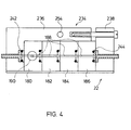
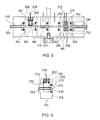
- FIGS. 4 and 5 show an electrode block 122 in a top view and a side view, the individual electrodes being shown schematically.
- Fig. 6 shows a single electrode in a side view.
- the electrode block 122 has four electrodes 180-186, the electrode 180 being specifically explained in more detail and also shown in FIG. 5 as a single electrode.
- Each of these electrodes 180-186 has a transverse bore 188 which forms the flow channel 24.
- the individual transverse bores 188 of the electrodes 180-186 are aligned and thus form the flow channel 24.
- each electrode 180-186 has a bore 190 perpendicular to the axis of the transverse bore 188, which leads to the cross bore 188.
- a concentric but narrower bore 192 is provided in the bore 190.
- the bottom area of the bore 190 is essentially completely covered by a liquid-impermeable membrane 194, which advantageously serves as a carrier membrane for an ion-selective substance.
- This membrane 194 is followed by a holding element 196 in the form of an insert, which is shown in FIGS. 5 and 10. It can also be seen from this FIG. 10 that the transverse bore 188 according to FIG. 5 can also be angled in the form of an angled transverse bore 198. Such a v-shaped guide has the advantage that the membrane 194 is flowed at more favorably, since the step formed by the bore 192 according to FIG. 5 can thereby be omitted.
- the bore 190 has a thread 200 into which a plug 202 is screwed, which presses the holding element 196 onto the membrane 194 and fixes it in position.
- the plug 202 is advantageously provided on its side facing the bore 190 with a circumferential annular groove 204, into which an O-ring is inserted, which, when the plug 202 is screwed in, lies sealingly against the wall of the bore 190 and thus prevents electrolyte liquid from flowing out.
- This plug 202 is penetrated by the Ag / AgCl diverter pin 208, which also protrudes through the holding element 196 and is in electrical contact with the electrolyte liquid.
- the bore 190 advantageously has a longitudinal groove 210 which receives a guide element 212 which is fixedly connected to the holding element 196 and thus prevents the holding element 196 from rotating when the plug 202 is screwed in.
- a tubular membrane 216 can also be used, which is advantageously designed as an ion-selective glass.
- This embodiment is shown specifically in FIG. 6 for electrode 184.
- the tubular electrode 216 extends through the electrode body 218, which has matching transverse bores 220 and 222, into which the tubular electrode is advantageously glued.
- the tubular electrode With its outer circumference, the tubular electrode is connected in the area of the bore 224 provided at right angles thereto, which is essentially the same as the bore 190 according to FIG. 10, but is further drawn down to form a blind hole, so that the tubular electrode 216 is completely is washed by electrolyte liquid.
- the bore 224 is again closed with a plug 202 with a diverter pin 208.
- the electrodes 180-186 advantageously each have on one side a bore 226 which is concentric to the transverse bore 188 or 220, 222 and is designed in the form of a blind hole.
- this bore 226 has an annular groove 228 in the base area, into which an O-ring 230 is inserted.
- the opposite side has a cylindrical elevation 232, which fits positively with the bore 226 of another electrode and compresses the O-ring 230 during assembly, the entire arrangement being sealed, as can be seen in FIGS. 4 and 5.
- a holder 234 which consists of a jaw 236 and a further jaw 238, which can be screwed together by a clamping screw 240.
- the clamping screw connects the jaw 238 to a leg of the jaw 236 which is guided past the rear side of the electrodes 180-186.
- these jaws 236 and 238 have a recess 242 and a cylindrical elevation 244, which corresponds to the bore 226 or the elevation 212 of the electrodes according to FIGS. 6 and 10 correspond.
- these jaws are each pierced with a transverse bore 246 and 248, which are aligned with the transverse bore 24 of the electrode block and thus form a flow arrangement. Furthermore, these jaws are each provided on their outside with a connecting piece 250 and 252 to which corresponding hoses can be connected, for example the hoses for the lines 30 and 32.
- clamping jaw 236 can have a vertical bore 254 into which a guide pin 256 is inserted can be used to screw the electrode block to a housing, not shown.
- the measuring device can have a conductivity measuring cell, which is shown schematically in FIG. 5 for the electrode 186.
- the conductivity measuring unit 260 this has three graphite disks 262, 264 and 266, which are each separated from one another by a sealing disk 258. All disks, i.e. the LF measuring unit 260 are in turn drilled with a transverse bore 270 which is aligned with the measuring channel. This transverse bore 270 is in each case directly connected to the LF measuring unit.
- a common line 272 extends from the outer graphite disks 262 and 266, while the middle graphite disk 264 is connected to the line 274.
- the two lines 272 and 274 are connected to the electrode connection device 294, for example in the form of the line 92.
- the conductivity is measured in the usual way by measuring the AC resistance at a frequency of 1-10, preferably about 3 kHz.
- All of the electrodes 180-186 in the electrode block 22 are advantageously made of transparent plastic glass, for example of polyacrylic glass, and enable seamless control of the measuring capillaries, that is to say of the flow channel 24, which advantageously has a diameter of approximately 1 mm.
- the electrode block 22 is advantageously made of aluminum up to the front, which is carried out by the holding device 234 in the example.
- the front is advantageously transparent and coated with an electrically conductive pad, for example an InO pad.
- the compact design of the electrodes 180-186 without any type of hose connection piece enables a short measuring channel, so that even with three parameters to be measured at the same time, the amount of sample is small and the security against clogging remains high by using a relatively large capillary as the flow channel 24.
- the choice of electrodes is determined by the intended use and is not critical in itself. So it can be the usual ion-selective electrodes, for example glass electrodes, plastic electrodes made of PVC, which have an ion-selective material, for example valinomycin, and the like. be used.
- the holes 190 and 224 are filled with the usual electrolyte solutions, for example sodium and / or potassium chloride solutions.
- this electrode block has a plurality of electrodes 284-288 which correspond in shape and arrangement to the previously described electrodes 180-186, so that reference is made to them.
- the reference electrode 280 is specially designed, which can be seen in particular from FIGS. 7-9.
- the reference electrode in turn has a vertical bore 290 which extends into the cuboid electrode body 292.
- This electrode body 292 is followed by a hollow leg 294 which covers the front of the electrodes 284-288 and which is in flow connection with a hollow leg 296 which is arranged at right angles in the horizontal and engages under all electrodes.
- the hollow leg 294 is in turn in flow connection with the bore 290 via a flow channel 298, with the result that all the hollow legs 294 and 296 can be filled with the reference electrolyte solution through the bore 290.
- This reference electrode otherwise corresponds in its structure to the electrode according to Fig. 10, wherein the membrane 194 is designed so that it allows the smallest possible amount of liquid in both directions.
- the electrolyte-filled plates or hollow legs 294 and 296 enclose the measuring electrodes 284 - 288 at the front and below, and due to the good electrical conductivity of the internal electrolyte, the high-resistance, interference-sensitive measuring electrodes 284 - 288 are shielded from external electrical fields up to a limit frequency above which no ionic ones Shifts can be observed, which consequently can no longer disturb.
- Such a closed reference electrode 280 has a maximum lifespan of approximately 6 weeks to approximately 6 months.
- the limitation of the service life is due to the contamination of the membrane 194 with interfering ions and deposits, in the decreasing concentration of the internal electrolyte due to the exchange via the membrane 194 and in the deterioration in the properties of the A gCl contact in the diverter pin 208 7-10 ge
- the reference electrode 280 although it is of a relatively complicated construction, is very easy to maintain because the wearing parts are easy to replace, while the electrode body 292 can be used again.
- the membrane 194 can be replaced by unscrewing the plug 202 and removing the holding or insert element 196. The membrane 194 is then exposed on the seat and can be removed and replaced with a new membrane.
- the holding element 196 and the plug 202 are reinserted, the latter fixing the holding element 196 and thus the membrane 194 in position by screwing them in.
- the internal electrolyte solution can be replaced by removing the plug 202 and withdrawing the liquid through an injection needle and replacing it with a fresh liquid.
Landscapes
- Health & Medical Sciences (AREA)
- Heart & Thoracic Surgery (AREA)
- Vascular Medicine (AREA)
- Urology & Nephrology (AREA)
- General Health & Medical Sciences (AREA)
- Biomedical Technology (AREA)
- Hematology (AREA)
- Life Sciences & Earth Sciences (AREA)
- Animal Behavior & Ethology (AREA)
- Engineering & Computer Science (AREA)
- Public Health (AREA)
- Veterinary Medicine (AREA)
- Anesthesiology (AREA)
- Emergency Medicine (AREA)
- Cardiology (AREA)
- Automatic Analysis And Handling Materials Therefor (AREA)
- External Artificial Organs (AREA)
- Investigating Or Analysing Biological Materials (AREA)
- Investigating Or Analyzing Materials By The Use Of Electric Means (AREA)
- Sampling And Sample Adjustment (AREA)
- Investigating Or Analyzing Non-Biological Materials By The Use Of Chemical Means (AREA)
- Measuring Or Testing Involving Enzymes Or Micro-Organisms (AREA)
Applications Claiming Priority (2)
| Application Number | Priority Date | Filing Date | Title |
|---|---|---|---|
| DE3416956A DE3416956C2 (de) | 1984-05-08 | 1984-05-08 | Meßvorrichtung zur Bestimmung der Aktivität oder der Konzentration von Ionen in Lösungen |
| DE3416956 | 1984-05-08 |
Publications (2)
| Publication Number | Publication Date |
|---|---|
| EP0163976A1 true EP0163976A1 (fr) | 1985-12-11 |
| EP0163976B1 EP0163976B1 (fr) | 1988-08-03 |
Family
ID=6235228
Family Applications (2)
| Application Number | Title | Priority Date | Filing Date |
|---|---|---|---|
| EP85105659A Expired EP0166920B1 (fr) | 1984-05-08 | 1985-05-08 | Dispositif pour enlever un liquide dialysant traité et non-traité et/ou du sang d'un dialyseur |
| EP85105658A Expired EP0163976B1 (fr) | 1984-05-08 | 1985-05-08 | Dispositif pour la détermination de l'activité ou de la concentration d'ions en solutions |
Family Applications Before (1)
| Application Number | Title | Priority Date | Filing Date |
|---|---|---|---|
| EP85105659A Expired EP0166920B1 (fr) | 1984-05-08 | 1985-05-08 | Dispositif pour enlever un liquide dialysant traité et non-traité et/ou du sang d'un dialyseur |
Country Status (4)
| Country | Link |
|---|---|
| US (2) | US4797191A (fr) |
| EP (2) | EP0166920B1 (fr) |
| JP (2) | JPS6129751A (fr) |
| DE (3) | DE3416956C2 (fr) |
Cited By (5)
| Publication number | Priority date | Publication date | Assignee | Title |
|---|---|---|---|---|
| EP0335859A3 (en) * | 1988-03-28 | 1990-08-29 | Avl Medical Instruments Ag | Device for determining components in a sample |
| EP0505530A4 (fr) * | 1990-09-13 | 1995-05-03 | David K Wong | |
| CN107850514A (zh) * | 2015-06-26 | 2018-03-27 | 基础科学公司 | 用于采集液体样品的系统 |
| US10585075B2 (en) | 2014-02-27 | 2020-03-10 | Elemental Scientific, Inc. | System for collecting liquid samples |
| US11054344B2 (en) | 2014-02-27 | 2021-07-06 | Elemental Scientific, Inc. | System for collecting liquid samples from a distance |
Families Citing this family (46)
| Publication number | Priority date | Publication date | Assignee | Title |
|---|---|---|---|---|
| DE3616062A1 (de) * | 1986-05-13 | 1987-11-19 | Fresenius Ag | Verfahren zur bestimmung von gaspartialdruecken im blut sowie vorrichtung zur durchfuehrung des verfahrens |
| DE3627814A1 (de) * | 1986-08-16 | 1988-02-25 | Fresenius Ag | Vorrichtung zur bestimmung des haematokrit |
| SE8801104L (sv) * | 1988-03-25 | 1989-09-26 | Beta Sensor Ab | Anordning foer maetning av parametrar i ett stroemmande fluidum samt saett att framstaella en daertill hoerande cell |
| JPH082608Y2 (ja) * | 1988-06-29 | 1996-01-29 | 株式会社堀場製作所 | 流通型イオン電極 |
| DE3832528C1 (fr) * | 1988-09-24 | 1989-11-16 | Fresenius Ag, 6380 Bad Homburg, De | |
| AT391215B (de) * | 1988-10-27 | 1990-09-10 | Avl Verbrennungskraft Messtech | Messgeraet zur erfassung chemischer parameter einer waessrigen probe |
| US4902399A (en) * | 1989-04-12 | 1990-02-20 | Abbott Laboratories | Flow-through electrochemical sensor |
| JPH0340556U (fr) * | 1989-08-31 | 1991-04-18 | ||
| JPH089638Y2 (ja) * | 1989-08-31 | 1996-03-21 | オリンパス光学工業株式会社 | 電解質測定装置のフローセル |
| JPH0789108B2 (ja) * | 1989-09-13 | 1995-09-27 | 株式会社日立製作所 | 電解質分析装置および電解質分析方法 |
| AT399228B (de) * | 1990-06-08 | 1995-04-25 | Avl Verbrennungskraft Messtech | Verfahren zur analyse von gasförmigen oder flüssigen proben und einweg-messelement zur ausübung des verfahrens |
| SE467074B (sv) * | 1990-09-24 | 1992-05-18 | Tecator Ab | Saett att maeta jonhalten i vattenprover samt anordning foer utfoerande av saettet |
| US5258314A (en) * | 1991-03-18 | 1993-11-02 | Paradigm Biotechnologies Partnership | Microprocessor-based biomedical monitoring apparatus and method |
| FR2684864A1 (fr) * | 1991-12-12 | 1993-06-18 | Hemodia | Procede et dispositif pour mesurer la concentration d'une substance dans un milieu complexe liquide, par exemple le sang. |
| SE505028C2 (sv) * | 1992-05-13 | 1997-06-16 | Electrolux Ab | Förfarande och anordning för rening av vatten |
| FR2712822B1 (fr) * | 1993-11-26 | 1996-05-15 | Hospal Ind | Dispositif et procédé de vérification des performances d'un échangeur. |
| DE4401400A1 (de) * | 1994-01-19 | 1995-07-20 | Ernst Prof Dr Pfeiffer | Verfahren und Anordnung zur kontinuierlichen Überwachung der Konzentration eines Metaboliten |
| AU6084496A (en) * | 1995-11-03 | 1997-05-08 | Ciba Corning Diagnostics Corp. | Reference electrode assembly |
| DE29902953U1 (de) * | 1999-02-19 | 2000-07-13 | Fresenius Medical Care Deutschland GmbH, 61352 Bad Homburg | Vorrichtung zur Dialysebehandlung |
| US20030015423A1 (en) * | 1999-03-04 | 2003-01-23 | Lagreca Alfred J. | Method and apparatus for calibrating a pH/ISE meter |
| US20030019748A1 (en) * | 2001-06-19 | 2003-01-30 | Elena Viltchinskaia | Method and apparatus for stripping voltammetric and potent iometric detection and measurement of contamination in liquids |
| US20030015437A1 (en) * | 2001-07-09 | 2003-01-23 | University Of Delaware | Method for in-situ analysis and flow cell therefor |
| US7241272B2 (en) | 2001-11-13 | 2007-07-10 | Baxter International Inc. | Method and composition for removing uremic toxins in dialysis processes |
| US7407570B2 (en) * | 2002-03-13 | 2008-08-05 | The Charles Stark Draper Laboratory, Inc. | Disposable, self-administered electrolyte test |
| US7101472B2 (en) * | 2002-03-13 | 2006-09-05 | The Charles Stark Draper Laboratory, Inc. | Microfluidic ion-selective electrode sensor system |
| MXPA05000816A (es) | 2002-07-19 | 2005-04-28 | Baxter Int | Sistemas y metodos para realizar dialisis peritoneal. |
| US8803044B2 (en) | 2003-11-05 | 2014-08-12 | Baxter International Inc. | Dialysis fluid heating systems |
| US8038639B2 (en) | 2004-11-04 | 2011-10-18 | Baxter International Inc. | Medical fluid system with flexible sheeting disposable unit |
| US8029454B2 (en) | 2003-11-05 | 2011-10-04 | Baxter International Inc. | High convection home hemodialysis/hemofiltration and sorbent system |
| US20060276748A1 (en) * | 2005-05-17 | 2006-12-07 | Infussafe Llc | Infusion monitoring device system and method |
| US8114276B2 (en) | 2007-10-24 | 2012-02-14 | Baxter International Inc. | Personal hemodialysis system |
| US8062513B2 (en) | 2008-07-09 | 2011-11-22 | Baxter International Inc. | Dialysis system and machine having therapy prescription recall |
| US9297797B2 (en) * | 2009-07-01 | 2016-03-29 | Beckman Coulter, Inc. | Ion selective electrode module for clinical diagnostics |
| FR2951950B1 (fr) | 2009-10-30 | 2012-02-17 | Rd Nephrologie | Dispositif et procede de caracterisation d'un traitement extracorporel du sang, et appareil de traitement extracorporel mettant en oeuvre un tel dispositif. |
| US9861733B2 (en) | 2012-03-23 | 2018-01-09 | Nxstage Medical Inc. | Peritoneal dialysis systems, devices, and methods |
| JP6049685B2 (ja) | 2011-03-23 | 2016-12-21 | ネクステージ メディカル インコーポレイテッド | 腹膜透析使い捨てユニット、コントローラ、腹膜透析システム |
| WO2015115303A1 (fr) * | 2014-01-31 | 2015-08-06 | 株式会社日立ハイテクノロジーズ | Électrode sélective d'ions du type à écoulement, dispositif de mesure de concentration d'électrolyte l'utilisant, et analyseur biochimique automatique |
| US20160356874A1 (en) * | 2015-06-02 | 2016-12-08 | Fresenius Medical Care Holdings, Inc. | Sensor Calibration for Dialysis Systems |
| US10503177B2 (en) * | 2016-08-03 | 2019-12-10 | Safe Harbor Associates LLC | Additive delivery system with sensors |
| WO2018237375A1 (fr) | 2017-06-24 | 2018-12-27 | Nxstage Medical, Inc. | Procédés et systèmes de préparation et/ou de traitement de fluide de dialyse péritonéale |
| CA3092575A1 (fr) | 2018-02-28 | 2019-09-06 | Nxstage Medical, Inc. | Dispositifs, procedes et systemes de preparation de fluide et de traitement |
| JP7611788B2 (ja) * | 2021-08-06 | 2025-01-10 | 株式会社日立ハイテク | 電解質測定用構造およびそれを用いたフロー型イオン選択性電極、ならびに電解質測定装置 |
| US12656227B2 (en) | 2021-11-17 | 2026-06-16 | Analog Devices International Unlimited Company | Sensing system with improved fluidics control |
| GB2614308B (en) * | 2021-12-24 | 2024-10-02 | Kalium Health Ltd | Apparatus and method |
| JP7847555B2 (ja) * | 2023-03-17 | 2026-04-17 | 株式会社日立ハイテク | 電解質分析装置、及び電解質分析装置の異常判定方法 |
| WO2025220386A1 (fr) * | 2024-04-15 | 2025-10-23 | 株式会社日立ハイテク | Dispositif d'analyse d'électrolyte et procédé de commande |
Citations (6)
| Publication number | Priority date | Publication date | Assignee | Title |
|---|---|---|---|---|
| US3556950A (en) * | 1966-07-15 | 1971-01-19 | Ibm | Method and apparatus for automatic electrochemical analysis |
| DD132210A1 (de) * | 1977-07-08 | 1978-09-06 | Udo Gruenke | Verfahren und einrichtung zur kontinuierlichen elektrochemischen analyse |
| DE2726772A1 (de) * | 1977-06-14 | 1979-01-04 | Fresenius Chem Pharm Ind | Mehrfachmessystem fuer die elektrochemische analyse stroemender fluessigkeiten und gase |
| DE2908719A1 (de) * | 1978-03-10 | 1979-09-13 | Olympus Optical Co | Verfahren und vorrichtung zur messung der ionenaktivitaet |
| DE3206049A1 (de) * | 1982-02-19 | 1983-09-08 | Franz-Josef Prof. Dr. 3550 Marburg Haberich | Messanordnung fuer die potentiometrische oder polarographische analyse von messloesungen |
| AT377366B (de) * | 1981-05-25 | 1985-03-11 | List Hans | Analysengeraet, insbesondere zur untersuchung von fluessigkeitsproben |
Family Cites Families (29)
| Publication number | Priority date | Publication date | Assignee | Title |
|---|---|---|---|---|
| NL257371A (fr) * | 1959-10-30 | |||
| US3151052A (en) * | 1962-05-17 | 1964-09-29 | Beckman Instruments Inc | Electrochemical flow cell |
| US3441136A (en) * | 1966-07-07 | 1969-04-29 | Milton Roy Co | Controlled blood dialysis system |
| GB1213459A (en) * | 1967-03-21 | 1970-11-25 | Lucas Industries Ltd | Artificial kidney machines |
| CA959721A (en) * | 1969-12-17 | 1974-12-24 | Cecil M. Burns | Precision deposition onto a textile substrate |
| FR2085298A1 (fr) * | 1970-04-07 | 1971-12-24 | Moulet Camille | |
| US3722680A (en) * | 1971-03-17 | 1973-03-27 | F Smith | Hemodialysis apparatus |
| IT984697B (it) * | 1973-05-25 | 1974-11-20 | Bellco Spa | Diluitore di concentrato per la preparazione del liquido di dia lisi in reni artificiali |
| JPS5544619B2 (fr) * | 1974-12-23 | 1980-11-13 | ||
| US3926561A (en) * | 1974-05-13 | 1975-12-16 | Meloy Lab | Gas analysis employing semi-permeable membrane |
| US4430098A (en) * | 1976-03-24 | 1984-02-07 | Bowman Donald B | Apparatus for degassing hemodialysis liquid and the like |
| US4119406A (en) * | 1976-05-06 | 1978-10-10 | Miles Laboratories, Inc. | Calibration apparatus |
| US4127111A (en) * | 1976-10-26 | 1978-11-28 | Drolet Roland A | Automatic blood sampling system and method |
| SE7613375L (sv) * | 1976-11-30 | 1978-05-31 | Gambro Ab | Sett och anordning for metning av koncentrationen av en lagmolekyler forening i ett komplex medium |
| US4230601A (en) * | 1978-05-03 | 1980-10-28 | Eastman Kodak Company | Calibrator composition based upon dialyzed blood serum |
| FI70473C (fi) * | 1978-06-23 | 1986-09-19 | Inst Biologicheskoi Fiz | Peristaltisk doserare och medelst denna foerverkligat doseringssystem |
| US4202747A (en) * | 1978-07-06 | 1980-05-13 | Beckman Instruments, Inc. | Flow cell fluid and sample supply mechanism |
| US4218197A (en) * | 1978-07-06 | 1980-08-19 | Beckman Instruments, Inc. | Combined peristaltic pump and valve flow controller |
| JPS5538165A (en) * | 1978-09-12 | 1980-03-17 | Senko Med Instr Mfg | Method of measuring degree of dialysis |
| IT1134064B (it) * | 1979-11-15 | 1986-07-24 | Extracorporeal Med Spec | Regolatore della pressione |
| US4253847A (en) * | 1980-01-03 | 1981-03-03 | Environmental Sciences Associates, Inc. | Preparing sample for electrochemical testing system |
| US4283262A (en) * | 1980-07-01 | 1981-08-11 | Instrumentation Laboratory Inc. | Analysis system |
| JPS5778866A (en) * | 1980-11-05 | 1982-05-17 | Olympus Optical Co | Monitor device for component in body fluid |
| JPS57103650A (en) * | 1980-12-19 | 1982-06-28 | Denki Kagaku Keiki Kk | Method of monitoring artificial kidney |
| US4424276A (en) * | 1981-12-07 | 1984-01-03 | Intermountain Health Care | Method and apparatus for measuring the gaseous content of blood |
| DE3223051C2 (de) * | 1982-06-21 | 1984-09-13 | Fresenius AG, 6380 Bad Homburg | Dialysevorrichtung mit geregelter Dialysierlösung |
| EP0097366B1 (fr) * | 1982-06-21 | 1988-09-07 | Fresenius AG | Dispositif de dialyse avec composition contrôlée de la solution de dialyse |
| DD216630A1 (de) * | 1983-06-03 | 1984-12-19 | Messgeraetewerk Zwonitz Veb K | Vorrichtung fuer die single-needle-dialyse |
| US4627893A (en) * | 1984-03-28 | 1986-12-09 | Amdev, Inc. | Means and methods for quantitative determination of analyte in liquids |
-
1984
- 1984-05-08 DE DE3416956A patent/DE3416956C2/de not_active Expired
-
1985
- 1985-05-08 DE DE8585105658T patent/DE3564157D1/de not_active Expired
- 1985-05-08 EP EP85105659A patent/EP0166920B1/fr not_active Expired
- 1985-05-08 DE DE8585105659T patent/DE3563816D1/de not_active Expired
- 1985-05-08 US US06/732,022 patent/US4797191A/en not_active Expired - Lifetime
- 1985-05-08 JP JP9768585A patent/JPS6129751A/ja active Granted
- 1985-05-08 JP JP9768685A patent/JPS6129359A/ja active Granted
- 1985-05-08 EP EP85105658A patent/EP0163976B1/fr not_active Expired
- 1985-05-08 US US06/732,025 patent/US4662208A/en not_active Expired - Lifetime
Patent Citations (6)
| Publication number | Priority date | Publication date | Assignee | Title |
|---|---|---|---|---|
| US3556950A (en) * | 1966-07-15 | 1971-01-19 | Ibm | Method and apparatus for automatic electrochemical analysis |
| DE2726772A1 (de) * | 1977-06-14 | 1979-01-04 | Fresenius Chem Pharm Ind | Mehrfachmessystem fuer die elektrochemische analyse stroemender fluessigkeiten und gase |
| DD132210A1 (de) * | 1977-07-08 | 1978-09-06 | Udo Gruenke | Verfahren und einrichtung zur kontinuierlichen elektrochemischen analyse |
| DE2908719A1 (de) * | 1978-03-10 | 1979-09-13 | Olympus Optical Co | Verfahren und vorrichtung zur messung der ionenaktivitaet |
| AT377366B (de) * | 1981-05-25 | 1985-03-11 | List Hans | Analysengeraet, insbesondere zur untersuchung von fluessigkeitsproben |
| DE3206049A1 (de) * | 1982-02-19 | 1983-09-08 | Franz-Josef Prof. Dr. 3550 Marburg Haberich | Messanordnung fuer die potentiometrische oder polarographische analyse von messloesungen |
Cited By (11)
| Publication number | Priority date | Publication date | Assignee | Title |
|---|---|---|---|---|
| EP0335859A3 (en) * | 1988-03-28 | 1990-08-29 | Avl Medical Instruments Ag | Device for determining components in a sample |
| AT391950B (de) * | 1988-03-28 | 1990-12-27 | Avl Verbrennungskraft Messtech | Vorrichtung zur messung von in einer probe vorliegenden probenbestandteilen |
| EP0505530A4 (fr) * | 1990-09-13 | 1995-05-03 | David K Wong | |
| US10585075B2 (en) | 2014-02-27 | 2020-03-10 | Elemental Scientific, Inc. | System for collecting liquid samples |
| US11054344B2 (en) | 2014-02-27 | 2021-07-06 | Elemental Scientific, Inc. | System for collecting liquid samples from a distance |
| US11933698B2 (en) | 2014-02-27 | 2024-03-19 | Elemental Scientific, Inc. | System for collecting liquid samples from a distance |
| US12366560B2 (en) | 2014-02-27 | 2025-07-22 | Elemental Scientific, Inc. | System for collecting liquid samples |
| CN107850514A (zh) * | 2015-06-26 | 2018-03-27 | 基础科学公司 | 用于采集液体样品的系统 |
| US10585108B2 (en) | 2015-06-26 | 2020-03-10 | Elemental Scientific, Inc. | System for collecting liquid samples |
| US11249101B2 (en) | 2015-06-26 | 2022-02-15 | Elemental Scientific, Inc. | System for collecting liquid samples |
| US12174211B2 (en) | 2015-06-26 | 2024-12-24 | Elemental Scientific, Inc. | System for collecting liquid samples |
Also Published As
| Publication number | Publication date |
|---|---|
| JPH0211262B2 (fr) | 1990-03-13 |
| JPS6129751A (ja) | 1986-02-10 |
| DE3563816D1 (en) | 1988-08-25 |
| EP0166920A1 (fr) | 1986-01-08 |
| EP0166920B1 (fr) | 1988-07-20 |
| DE3564157D1 (en) | 1988-09-08 |
| JPH0476427B2 (fr) | 1992-12-03 |
| JPS6129359A (ja) | 1986-02-10 |
| DE3416956C2 (de) | 1986-12-04 |
| DE3416956A1 (de) | 1985-11-21 |
| EP0163976B1 (fr) | 1988-08-03 |
| US4662208A (en) | 1987-05-05 |
| US4797191A (en) | 1989-01-10 |
Similar Documents
| Publication | Publication Date | Title |
|---|---|---|
| EP0163976B1 (fr) | Dispositif pour la détermination de l'activité ou de la concentration d'ions en solutions | |
| DE2554803C2 (de) | Elektrochemisches Analyseverfahren sowie Vorrichtung zur Durchführung des Verfahrens | |
| DE102005060866B4 (de) | Kombinierte Titrations- und pH-Elektrode für die Präparation von flüssigen Messproben insbesondere für die NMR-Spektroskopie | |
| EP0084874B1 (fr) | Appareil pour la détermination de l'hématocrite | |
| DE2927048C2 (de) | Vorrichtung zur Durchführung analytischer Messungen an einer Flüssigkeit | |
| EP0121742B1 (fr) | Dispositif d'analyse électrochimique de composants électrolytiques dans un fluide à examiner | |
| DE3116321C2 (fr) | ||
| DE2528819A1 (de) | Analysegeraet | |
| DE3501137A1 (de) | Vorrichtung und verfahren zur quantitativen bestimmung von analyten in fluessigkeiten | |
| DE102010063033A1 (de) | Verfahren zur Inbetriebnahme eines Messgeräts | |
| DE102010030874A1 (de) | Potentiometrische Sonde zur Messung einer Messgröße eines in einem Behälter enthaltenen Messmediums | |
| DE2265200C3 (de) | Strömungszelle für Zwecke der elektrochemischen Analyse | |
| DE2215486B2 (de) | MeBgefäßanordnung für ein Teilchenmeßgerät | |
| DE2811972A1 (de) | Teilchen-zaehler fuer blutbestandteile | |
| EP0335859B1 (fr) | Dispositif de mesure de composants présents dans un échantillon | |
| EP0247535B1 (fr) | Electrode de référence pour la mesure de l'activité ionique, en particulier pour la mesure de pH | |
| DE1598973B2 (de) | Elektrodenmesskette zur bestimmung des ph-wertes | |
| EP0366645B1 (fr) | Appareil de mesure pour déterminer un paramètre chimique dans un échantillon aqueux | |
| DE4227338A1 (de) | Verfahren und Durchflußmeßanordnung zur Analyse von Flüssigkeiten | |
| DE69015231T2 (de) | Salzbrücke für eine Vorrichtung zur chemischen Analyse. | |
| DE10233902B4 (de) | Messgerät mit einem Griffteil | |
| DE2900720C2 (fr) | ||
| WO1998005958A1 (fr) | Dispositif pour loger de façon interchangeable des cartouches ou des cellules de mesure, pour determiner des parametres de mesure biochimiques dans des systemes d'analyse commandes par ordinateur, et dispositifs associes utilises dans lesdites cartouches ou cellules de mesure | |
| DE4227323A1 (de) | Halbautomatisches Verfahren und Durchflußmeßanordnung zur Analyse von Flüssigkeiten | |
| EP0163206A2 (fr) | Dispositif pour la mesure de propriétés données de particules en suspension dans un milieu porteur |
Legal Events
| Date | Code | Title | Description |
|---|---|---|---|
| PUAI | Public reference made under article 153(3) epc to a published international application that has entered the european phase |
Free format text: ORIGINAL CODE: 0009012 |
|
| AK | Designated contracting states |
Designated state(s): DE FR GB IT |
|
| 17P | Request for examination filed |
Effective date: 19860124 |
|
| 17Q | First examination report despatched |
Effective date: 19871204 |
|
| GRAA | (expected) grant |
Free format text: ORIGINAL CODE: 0009210 |
|
| AK | Designated contracting states |
Kind code of ref document: B1 Designated state(s): DE FR GB IT |
|
| GBT | Gb: translation of ep patent filed (gb section 77(6)(a)/1977) | ||
| REF | Corresponds to: |
Ref document number: 3564157 Country of ref document: DE Date of ref document: 19880908 |
|
| ITF | It: translation for a ep patent filed | ||
| ET | Fr: translation filed | ||
| PLBE | No opposition filed within time limit |
Free format text: ORIGINAL CODE: 0009261 |
|
| STAA | Information on the status of an ep patent application or granted ep patent |
Free format text: STATUS: NO OPPOSITION FILED WITHIN TIME LIMIT |
|
| 26N | No opposition filed | ||
| ITTA | It: last paid annual fee | ||
| REG | Reference to a national code |
Ref country code: GB Ref legal event code: IF02 |
|
| PGFP | Annual fee paid to national office [announced via postgrant information from national office to epo] |
Ref country code: GB Payment date: 20040426 Year of fee payment: 20 |
|
| PGFP | Annual fee paid to national office [announced via postgrant information from national office to epo] |
Ref country code: FR Payment date: 20040519 Year of fee payment: 20 |
|
| PGFP | Annual fee paid to national office [announced via postgrant information from national office to epo] |
Ref country code: DE Payment date: 20040729 Year of fee payment: 20 |
|
| PG25 | Lapsed in a contracting state [announced via postgrant information from national office to epo] |
Ref country code: GB Free format text: LAPSE BECAUSE OF EXPIRATION OF PROTECTION Effective date: 20050507 |
|
| REG | Reference to a national code |
Ref country code: GB Ref legal event code: PE20 |