EP0163228A2 - Einlass-Absperrventil für Drehkolbenpumpen - Google Patents
Einlass-Absperrventil für Drehkolbenpumpen Download PDFInfo
- Publication number
- EP0163228A2 EP0163228A2 EP85106167A EP85106167A EP0163228A2 EP 0163228 A2 EP0163228 A2 EP 0163228A2 EP 85106167 A EP85106167 A EP 85106167A EP 85106167 A EP85106167 A EP 85106167A EP 0163228 A2 EP0163228 A2 EP 0163228A2
- Authority
- EP
- European Patent Office
- Prior art keywords
- valve
- oil
- vacuum pump
- pressure
- inlet
- Prior art date
- Legal status (The legal status is an assumption and is not a legal conclusion. Google has not performed a legal analysis and makes no representation as to the accuracy of the status listed.)
- Withdrawn
Links
Images


Classifications
-
- F—MECHANICAL ENGINEERING; LIGHTING; HEATING; WEAPONS; BLASTING
- F04—POSITIVE - DISPLACEMENT MACHINES FOR LIQUIDS; PUMPS FOR LIQUIDS OR ELASTIC FLUIDS
- F04C—ROTARY-PISTON, OR OSCILLATING-PISTON, POSITIVE-DISPLACEMENT MACHINES FOR LIQUIDS; ROTARY-PISTON, OR OSCILLATING-PISTON, POSITIVE-DISPLACEMENT PUMPS
- F04C28/00—Control of, monitoring of, or safety arrangements for, pumps or pumping installations specially adapted for elastic fluids
- F04C28/28—Safety arrangements; Monitoring
-
- F—MECHANICAL ENGINEERING; LIGHTING; HEATING; WEAPONS; BLASTING
- F04—POSITIVE - DISPLACEMENT MACHINES FOR LIQUIDS; PUMPS FOR LIQUIDS OR ELASTIC FLUIDS
- F04C—ROTARY-PISTON, OR OSCILLATING-PISTON, POSITIVE-DISPLACEMENT MACHINES FOR LIQUIDS; ROTARY-PISTON, OR OSCILLATING-PISTON, POSITIVE-DISPLACEMENT PUMPS
- F04C29/00—Component parts, details or accessories of pumps or pumping installations, not provided for in groups F04C18/00 - F04C28/00
- F04C29/02—Lubrication; Lubricant separation
- F04C29/021—Control systems for the circulation of the lubricant
Definitions
- the present invention relates generally to rotary piston vacuum pumps and, more particularly, to such pumps having antisuckback features which cut off the flow of lubricant from the stopped pump into the low pressure operating chamber.
- an oil pump may be added in the oil circuit of a mechanical vacuum pump to provide a forced oil flow throughout the operating pressure range of the vacuum pump.
- the oil pump In a compound (two stage) mechanical vacuum pump, the oil pump is typically added in the oil circuit of the second or roughing stage, while the first or high vacuum stage oil flow is induced by the small pressure differential and gravity.
- interstage degassed oil is typically recirculated in a separate and independent oil circuit through the first stage pumping chamber because atmospheric pressure oil often contains air which, if released in the first stage, would drastically decrease net pump capacity.
- each pumping chamber therein may be at a different pressure.
- the first stage being in communication with the operating chamber or low pressure chamber being evacuated at the pump inlet, is at a relatively low pressure as compared with the pressure in the second stage, being in communication with the pump outlet through the discharge separator.
- This differential pressure between pumping chambers often results in the lubricating and sealing oil seeping or flowing back between working elements into the first pumping chamber.
- this seepage or back flow typically contaminates the degassed oil supply of the first pumping chamber.
- the operating chamber is contaminated.
- Prior vacuum pumps have been equipped with devices to stop the oil flow into the pumping chambers or stages when the vacuum pump is stopped under vacuum or low pressure conditions in the pumping chamber. These devices attempt to avoid flooding the pump chamber and, in turn, oil flowing back through the pump inlet system and to contaminate any operating chamber attached thereto. By preventing oil flooding of the pump, problems associated with starting of a flooded pump are also eliminated.
- the method and/or device for preventing flow of oil back into the inlet system is typically called an "antisuckback" device.
- Previous oil backflow prevention devices have included solenoid valves or centrifugally operated mechanisms having, for example, resilient elastomer plunger seals which shut-off oil flow into the stopped pump. However, these devices are relatively expensive and may lack a high level of responsiveness to sudden changes in pump operation. These so-called antisuckback devices are commonly incorporated in oil sealed rotary vane vacuum pumps.
- Another object is the provision of improved antisuckback devices for rotary piston pumps having hydraulically actuated control valves for simultaneously controlling lubricant flow and pumping chamber pressure relief.
- a further object is to provide an improved, hydraulically controlled antisuckback device for compound or multi-stage vacuum pumps having an inlet line shut-off valve seal sufficient to prevent leakage past that valve at low pressures.
- Still another object is the provision of a means of achieving pressure equalization in the pump chamber after stopping the vacuum pump and further preventing backflow of lubricant thereto and into the operating chamber by means of a highly responsive shut-off valve in the working fluid inlet flow path.
- a shaft lip seal as an inlet shut-off valve seal in the working fluid inlet line of a rotary piston pump between the first pumping chamber of the vacuum pump and the inlet to the operating chamber.
- a piston valve is provided, having an axially inclined radial face, for engaging this seal and cutting off flow therebetween even under low pressures. This piston valve is actuated into sealing engagement with the shaft lip seal when operation of the vacuum pump ceases and a pressure relief vent is connected to the first pumping chamber.
- An arrangement for connecting a pressure relief vent to the first pumping chamber when the vacuum pump is stopped is provided by an oil pump in the lubricating oil circuit, a pressure relief vent connected to the pumping chamber from a higher pressure source, and biased valve connected between the oil pump and the oil circuit as well as between the pressure relief vent and the first pumping chamber for controlling the flow of oil and pressure, respectively.
- the oil pump pressurizes the oil in the oil lubrication circuit as a function of vacuum pump operation.
- the valve is responsive to the oil pressure created by the oil pump. The valve is actuated to maintain the free flow of oil from the oil pump to the oil circuit when the vacuum pump is operating.
- the bias of the valve shuts off the flow of oil through the oil circuit and opens the connection between the pressure relief vent and the first pumping chamber to increase the pressure in the latter such that lubricating oil is not drawn into that pumping chamber.
- This increased pressure from the pressure relief vent actuates an inlet shut-off valve which isolates the first pressure chamber from the operating chamber.
- the valve arrangement of the present invention can simultaneously control oil flow in a plurality of those oil circuits. Pressurized oil from a single oil circuit provides the control signal to actuate the valve arrangement. Thus, only that oil circuit requires an oil pump.
- the pressure relief vent, connected tc at least The first pumping chamber, is also controlled by the valve arrangement.
- the valve arrangement may include either a single slide valve intersecting each oil circuit and pressure relief path to the pumping chambers or multiple slide valves each intersecting one or more oil circuit and/or pressure relief paths.
- the valve arrangement responds to the oil pressure drop in the oil circuit providing its control signal to prevent oil flow to at least the first pumping chamber and simultaneously permit pressure relief to that pumping chamber.
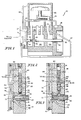
- cross-sectional views of Figures 4 and 5 are on planes generally perpendicular to the planes of the cross-sectional views of Figures 1, 2 and 3.
- Figure 6 shows a partial cross-sectional view of an enlarged portion of Figure 4 illustrating in detail the inlet shut-off valve arrangement of the present invention without the flow lines past inlet shut-off valve 220.
- Figure 1 which illustrates a preferred embodiment of the present invention, shows a partial cross-sectional view of a two-stage rotary pump 10 having a housing 15 with first and second pumping chambers 20 and 25, respectively, therein.
- Drive shaft 30 is mounted through first and second pumping chambers 20 and 25, and is supported by housing 15.
- First and second pumping chambers 20 and 25 are each provided with an independent oil circuit to lubricate operating elements within that chamber and seal clearances between relatively moving members.
- the oil circuit employs degassed oil from reservoir 35.
- Degassed oil flows out of reservoir 35 along line 37 to valve member 50 (shown in Figures 2 and 3 and discussed in detail herein below) at portion A. From there degassed fluid flow continues to line 41 directly to first pumping chamber 20 or to line 39 within drive shaft 30 to outlet ports 43 within first pumping chamber 20.
- the rotating and reciprocating action of the piston pump (not shown) of first pumping chamber 20 results in the return flow of degassed oil to reservoir 35.
- the oil circuit of second pumping chamber 25 includes oil reservoir 45. Oil flows from that reservoir through line 47 and then to valve 50 at portion A. Oil flow returns along line 49 from valve 50 to drive shaft 30 at bearing 32. Oil flows along drive shaft 30 to second pumping chamber 25 and is carried by pumping action therein to reservoir 45 and, through conduit 81, to discharge separator 80. Discharge separator 80 passes the vacuum pump working fluid, typically air, to the vacuum pump atmospheric outlet (not shown) and returns oil carried thereby to reservoir 45 through conduit 81. Discharge separator 80 is also provided with a pressure relief vent line 82 for providing a flow of working fluid back to valve 50.
- Discharge separator 80 passes the vacuum pump working fluid, typically air, to the vacuum pump atmospheric outlet (not shown) and returns oil carried thereby to reservoir 45 through conduit 81.
- Discharge separator 80 is also provided with a pressure relief vent line 82 for providing a flow of working fluid back to valve 50.
- the present invention provides means for preventing excess oil flow into the pumping chambers when the vacuum pump has been stopped. This is accomplished by a hydraulically responsive valve arrangement which both interrupts the oil circuit and equalizes the pressures within the pumping chambers when vacuum pump operation ceases. More specifically, in the exemplary two stage vacuum pump 10 of Figure 1, oil from both reservoirs 35 and 45 is prevented from flowing into first and second pumping chambers 20 and 25 when hydraulic control signals to valve 50 indicate the vacuum pump has stopped. At the same time, valve 50 permits the flow of discharged working fluid through line 82 to first pumping chamber 20 to provide pressure relief. Thus, when the vacuum pump has stopped, valve 50 permits pressure equalization between first and second pumping chambers 20 and 25, respectively.
- the hydraulic control signals applied to valve 50 result from pressurization of oil by oil pump 70 from reservoir 45 only. Oil pump 70 operates in response to operation of vacuum pump 10.
- Figure 2 shows a partial cross-sectional view enlarging that portion of Figure 1 designated by "A".
- the position of valve 50 in Figure 2 is shown for when vacuum pump 10 is operating. This figure may be compared with a similar cross-sectional view of Figure 3 illustrating the position of valve 50 when the vacuum pump has been stopped.
- valve 50 is, for example, a slide valve movable along bore 56, biased upwardly by spring 52.
- Valve 50 is actuated downwardly by oil pressure in bore chamber 54 to oppose the spring bias of spring 52.
- An oil pump 70 is provided as, for example, a gear pump driven by extension 72 of drive shaft 30 past sealing means 34 and having gear members 74. Oil from reservoir 45 incoming on line 47 is pressurized by the pumping action of oil pump 70, and, when vacuum pump 10 is in operation, then flows along line 76 to sealing line 78 and input line 62 to bore chamber 54 of valve 50.
- Degassed oil from reservoir 35 flows along line 37 to valve 50 and is not subject to pumping pressurization. This degassed oil flows through the degassed oil circuit only as a result of gravitational and pressure differential forces.
- Incoming degassed oil on line 37 passes through control valve 50 along line 58 when vacuum pump 10 is operating.
- Degassed oil from line 58 exits bore 56 to input ports 36 of drive shaft 30. This oil then flows along line 39 within drive shaft 30 to outlet ports 43 or along line 41 directly to first pumping chamber 20.
- Pressure relief vent line 82 from discharge separator 80 reaches valve 50 through line 64.
- Line 68 communicates with pumping chamber 20.
- valve 50 blocks communication between lines 64 and 68.
- Pressurized oil from line 78 forms an oil seal at recess 60 on valve 50 between lines 64 and 68 to prevent leakage to first pumping chamber ?0 from pressure relief line 82.
- drive shaft 30 drives oil pump 70 to pressurize the oil in the oil circuit of second pumping chamber 25.
- oil pump 70 is not operating and does not pressurize that oil and, thus, oil pressure in chamber 54 does not overcome the spring bias of spring 52.
- Valve 50 will then move upwardly into bore chamber 54, as illustrated in Figure 3.
- valve 50 When valve 50 moves upwardly past the inlet to line 49, oil flow from reservoir 45 and line 62 to line 49 back to second pumping chamber 25 will be restricted and cut off. Simultaneously, the inlet to line 58 will move upwardly past the outlet of line 37 and oil flow from reservoir 35 and line 37 to lines 39 and 41 back to first pumping chamber 20 will be restricted and cut off. This same upward movement of valve 50 will cause the outlet of line 64 to align with the inlet of line 66 and, simultaneously, the outlet of line 66 to align with the inlet of line 68, permitting pressure relief to flow from discharge separator 80 to first pumping chamber 20.
- valve 50 cuts off oil flow in both of the oil circuits to pumping chambers 20 and 25, it opens up pressure relief flow to increase the pressure in first pumping chamber 20 and equalize the pressure between pumping chambers 20 and 25.
- oil flowback or seepage into either of the pumping chambers from either or both oil circuits is prevented when vacuum pump 10 is not operating.
- oil pump 70 When vacuum pump 10 resumes operation, oil pump 70 also resumes operation and will again pressurize oil in chamber 54. This causes valve 50 to move downwardly from bore chamber 54 against the bias of spring 52. Thereby, oil flow between lines 62 and 49 to second pumping chamber 25 and between lines 37, 58, and 39 and 41 to first pumping chamber 20 is permitted. Simultaneously, communication between lines 64, 66 and 68 from discharge separator 80 to first pumping chamber 20 is restricted and cut off. Likewise, high pressure oil communication from line 78 will be resumed with recess 60 and, thus, the oil seal between lines 64 and 68 will be reestablished when vacuum pump 10 resumes operation.
- Figures 4 and 5 show partial cross-sectional views of another rotary piston vacuum pump 110 having therein an alternative embodiment of the present invention.
- Figure 4 shows the location of the various antisuckback elements of the present invention when vacuum pump 110 is in operation.
- Figure 5 shows the location of the same elements when vacuum pump 110 has been stopped.
- Figures 4 and 5 are cross-sectional views along planes generally perpendicular to the views of Figures 1, 2 and 3.
- vacuum pump 110 may be a two chamber pump having separate oil circuits for each chamber and be similar to vacuum pump 10 in all other respects except those shown and described herein with respect to Figures 4 and 5.
- vacuum pump 110 includes housing 115, discharge separator 180, and first and second pumping chambers (not shown).
- Each pumping chamber includes an oil circuit associated therewith as in the embodiment of Figure 1.
- Each oil circuit includes an oil reservoir and oil lines extending to and from the antisuckback features of the present invention shown in Figures 4 and 5.
- vacuum pump 110 includes a plurality of valves.
- Valve 250 controls pressure relief to the first pumping chamber and equalization of pressure between pumping chambers.
- This valve also controls the flow of control signal oil to valve 150 which controls the flow of lubricating oil in both of the independent lubricating oil circuits.
- the valves are hydraulically actuated by oil pressure from an oil pump responsive to operation of vacuum pump 110.
- Valves 150 and 250 are, for example, biased by springs 152 and 252 and slidably disposed in bores 156 and 256, respectively.
- Bore chambers 154 and 254 are provided at the end of valves 150 and 250 which are opposite from springs 152 and 252, respectively. Thus, pressurized oil supplied to bore chambers 154 and 254 may overcome the biasing effect of springs 152 and 252, respectively, and cause valves 150 and 250 to be activated.
- Oil from the second pumping chamber flows through line 147 to oil pump 170 having pump gears 174.
- Oil pump 170 supplies pressurized oil along line 176 to bore chamber 254 of valve 250.
- Valve 250 is biased downwardly toward bore chamber 254 by spring 252.
- oil pump 170 supplies an oil pressure to bore chamber 254 which exceeds the biasing force of spring 252 and causes valve 250 to slide upwardly out of bore chamber 254, permitting oil flow to line 162 and then to bore chamber 154.
- Valve 250 includes valve element 255 at the end opposite bore chamber 254. Bore 256 includes valve seat 257 about the outlet of line 164 to valve 250. Bore 256 also includes outlet port 258 through a side wall of bore 256. Valve 250, for example, is illustrated as having a hollow portion interiorly of valve element 255. Line 164 receives pressure relief from discharge separator 180 along pressure relief vent 182. As shown in Figure 4, when valve 250 is forced up out of bore chamber 254 by oil pressure, valve element 255 covers the outlet of line 164 and seats against valve seat 257 to cut off pressure relief air flow through line 164 past valve element 255 and through outlet port 258 to line 168 and to the first pumping chamber.
- the pressure relief path to the first pumping chamber extends through a portion of bore 254 and then through outlet port 258 to line 168 to inlet .shut-off valve 220.
- the pressure relief path continues past valve 220 and into first pumping chamber inlet 240. However, when vacuum pump 110 is operating, inlet shut-off valve 220 rests against stop 222, at least partially blocking this relief pressure path.
- valve 150 When oil pressure causes valve 250 to move out of bore chamber 254, communication with line 162 is opened up and oil flows along line 162 to bore chamber 154 of valve 150. Valve 150 is biased upwardly toward bore chamber 154 by spring 152. As in valve 50 of Figures 2 and 3, valve 150 includes central degassed oil line 158 which may be aligned with lines 137 and 161 to permit degassed oil flow therethrough from the degassed oil reservoir of the first pumping chamber (not shown) to the first pumping chamber, through interior line 139 of the drive shaft (not shown). This alignment will result when vacuum pump 110 is operating and oil pressure in bore chamber 154 from line 176, bore 254, and line 162 causes valve 150 to slide downwardly in bore 156 to overcome the bias of spring 152, as shown in Figure 4. At the same time, valve 150 opens up communication with line 149, leading to the second pumping chamber (not shown), such that oil from line 162 may flow through bore chamber 154 to line 149 and the second pumping chamber.
- oil pump 170 is supplying pressurized oil to bore chambers 254 and 154, sequentially in the oil circuit of the second pumping chamber.
- This oil pressure causes valve 250 to cut off pressure relief from line 164 to the first pumping chamber by closing valve element 255 against valve seat 257 and opening inlet shut-off valve 220.
- the oil pressure causes valve 150 to permit oil flow to lines 139 and 149 leading to first and second pumping chambers, respectively.
- the oil pressure of only a single oil circuit (that of the second pumping chamber) is employed to provide hydraulic control signals actuating valve 150 to control oil flow through multiple oil circuits.
- valve 250 When, as illustrated in Figure 5, operation of vacuum pump 110 has ceased, oil pump 170 is also inoperative and does not supply pressurized oil flow through line 174 to valve 250 to overcome the spring bias of spring 252. Valve 250 then slides downwardly into bore chamber 254. Thus, valve element 255 disengages from valve seat 257 and permits pressure relief flow from discharge separator 180 through pressure relief vent line 182 and line 164 into bore 256 of valve 250 to line 168 and then to inlet shut-off valve 220.
- the pressure from discharge separator 180 is typically at a higher pressure than the pressure within the first pumping chamber.
- the differential pressure lifts inlet shut-off valve 220 off stop 222 and forces valve face 225 of inlet shut-off valve 220 to seat against inlet valve seal 230. This restricts pressure relief flow back through inlet filter 210 and vacuum pump inlet 200 to the operating chamber (not shown).
- inlet shut-off valve 220 is so actuated, relief pressure flow follows the working fluid path of vacuum pump 110 through first pumping chamber inlet 240 to the first pumping chamber. This results in an increase of the pressure within that pumping chamber and creates a pressure equilibrium between the first and second pumping chambers.
- valve 250 cuts off the flow of oil from lines 147 and 176 to line 162 and bore chamber 154.
- pressurized oil is not available to act on valve 150 to overcome the bias of spring 152.
- Valve 150 then slides upwardly into bore chamber 154, restricting and cutting off oil flow between bore chamber 154 and line 149 to the second pumping chamber as well as between lines 137, 158 and 139 to the first pumping chamber.
- the supply of oil available to be drawn into the pumping chambers by either low pressure or pressure differential is restricted. In combination with pressure relief to eliminate low pressure and pressure differential conditions, no significant back flow or oil flooding will result.
- inlet shut-off valve 220 further assures that no such contamination will result from lubricating oil in vacuum pump 110.
- oil pump 170 will resume operation and again pressurize the oil flow to cause valve 250 to shut-off the pressure relief flow to inlet shut-off valve 220.
- valve face 225 of inlet shut-off valve 220 will be unseated from valve seal 230 and drop to stop 222, permitting working fluid flow to resume from the operating vacuum chamber to pump 110.
- FIG 6 shows an enlarged, partial cross-sectional view of the portion of Figure 4 illustrating the inlet shut-off valve arrangement of the present invention without the presence of the flow lines of working fluid flow into the first pumping chamber past inlet shut-off valve 220 shown in Figure 4.
- Inlet shut-off valve 220 is, for example, a piston-like valve slidable within support 224 and cylindrical about centerline axis 300.
- Inlet shut-off valve 220 includes annular flange 227 extending radially therefrom about centerline axis 300.
- Support 224 includes stop 222 which limits movement of inlet shut-off valve 220 downwardly toward first pumping chamber inlet 240 by engagement with one side of flange 227.
- Valve face 225 is formed on flange 227 as an axially inclined surface on an otherwise radial face.
- Valve seal 230 comprises a shaft lip seal element normally employed to seal rotating drive shafts against grease or oil or working fluid flow. Shaft lip seals per se are standard, commercially available items. As conventionally employed, shaft lip seals are continuously radially compressed by the rotating shaft extending therethrough. However, in the present invention the shaft lip seal is employed to provide an axially resilient diametral seal against a valve face plate.
- the exemplary shaft lip seal included in valve seal 230 includes cantilevered seal 232, formed, for example, from a viton elastomer, extending in the direction of centerline axis 300 to form inner lip 236 supported by spring ring 234.
- the apex of inner lip 236 is significantly thinner than the rest of cantilevered seal 232.
- Spring ring 234 is formed, for example, from stainless steel.
- An example of a commercially available shaft lip seal suitable for use in the present invention is Chicago Rawhide part number 9982.
- the surface of valve face 225 which sealingly engages inner lip 236 may, for example, be formed from polished steel.
- valve seal 230 When valve face 225 and valve seal 230 are brought into engagement by actuation of inlet shut-off valve 220, the unique structure of the shaft lip seal permits fluid tight sealing over a wide range of pressures, including even very low pressures, within the operating chamber. This tight sealing results from the relative thinness of inner lip 236 which provides it with considerably greater flexibility than the rest of cantilevered seal 232. This flexibility permits greater conformity to the surface of valve face 225 while the use of otherwise hard seating viton elastomer assures the valve seal of strength and greater operating lifetime. Since valve seal 230 is formed from a readily available commercial part, expensive, specially adapted valve seals are not necessary.
- the inlet valve shut-off seal arrangement of the present invention provides considerable improvement over conventional flat elastomer seals in terms of durability and leakage prevention against both working fluid and lubricant.
- the present invention combines the advantages of hard elastomer seats and soft elastomer seats in a single, unique and inexpensive construction.
- the present invention has been described above with respect to oil flow and air pressure relief, it should be clearly understood that these embodiments are merely exemplary.
- the present invention contemplates the use of any other suitable lubricant besides oil to hydraulically actuate the valve arrangement controlling lubricant flow and pressure relief.
- Any other suitable fluid besides air such as a chemically inert gas or liquid, may be employed for pressure relief to the pumping chambers when the vacuum pump is not operating.
- the pressure relief vent need not be connected to the discharge separator.
- a different fluid, besides expelled working fluid may be employed for pressure relief.
- the pressure relief to the first pumping chamber need not be exactly equal to the pressure within the second pumping chamber. It is only necessary that this pressure relief be at least substantial. By this it is meant that the pressure relief should be at least sufficient to reduce the pressure differential, in combination with the lubricant flow restrictions, to prevent lubricant flow between pumping chambers and, in particular, into the first pumping chamber.
Landscapes
- Engineering & Computer Science (AREA)
- Mechanical Engineering (AREA)
- General Engineering & Computer Science (AREA)
- Applications Or Details Of Rotary Compressors (AREA)
- Compressors, Vaccum Pumps And Other Relevant Systems (AREA)
- Compressor (AREA)
Applications Claiming Priority (2)
| Application Number | Priority Date | Filing Date | Title |
|---|---|---|---|
| US61260084A | 1984-05-21 | 1984-05-21 | |
| US612600 | 1984-05-21 |
Publications (2)
| Publication Number | Publication Date |
|---|---|
| EP0163228A2 true EP0163228A2 (de) | 1985-12-04 |
| EP0163228A3 EP0163228A3 (de) | 1986-03-05 |
Family
ID=24453849
Family Applications (1)
| Application Number | Title | Priority Date | Filing Date |
|---|---|---|---|
| EP85106167A Withdrawn EP0163228A3 (de) | 1984-05-21 | 1985-05-20 | Einlass-Absperrventil für Drehkolbenpumpen |
Country Status (2)
| Country | Link |
|---|---|
| EP (1) | EP0163228A3 (de) |
| JP (1) | JPS60249691A (de) |
Cited By (2)
| Publication number | Priority date | Publication date | Assignee | Title |
|---|---|---|---|---|
| EP0519880A1 (de) * | 1991-06-17 | 1992-12-23 | GALILEO VACUUM TEC S.p.A. | Einlass-Absperrventil für Drehkolbenvakuumpumpen |
| WO1995004223A1 (de) * | 1993-07-28 | 1995-02-09 | Leybold Aktiengesellschaft | Vakuumpumpe mit einer gasballasteinrichtung |
Family Cites Families (7)
| Publication number | Priority date | Publication date | Assignee | Title |
|---|---|---|---|---|
| GB1195361A (en) * | 1966-03-28 | 1970-06-17 | N G N Ltd | Improvements in and relating to Vacuum Pumping apparatus including a Rotary Vacuum Pump |
| US3406897A (en) * | 1966-07-18 | 1968-10-22 | Leybold Holding Ag | Mechanical vacuum pump |
| DE1728277A1 (de) * | 1967-09-21 | 1972-06-15 | Edwards High Vacuum Internat L | Mehrstufige Rotorpumpe |
| US3698838A (en) * | 1971-02-11 | 1972-10-17 | Ingersoll Rand Co | Automatic fluid supply and control means |
| DE2451685A1 (de) * | 1974-10-31 | 1976-05-06 | Pfeiffer Vakuumtechnik | Vakuumpumpe mit eingebautem absperrventil |
| DD131487A1 (de) * | 1977-06-24 | 1978-06-28 | Juergen Kaunert | Absperrventil mit automatischer belueftungseinrichtung fuer vakuumpumpen |
| DD205219A1 (de) * | 1981-10-15 | 1983-12-21 | Pumpen U Verdichter Wissenscha | Hydraulisch-mechanische schutzeinrichtung fuer pumpen |
-
1985
- 1985-05-08 JP JP9766685A patent/JPS60249691A/ja active Pending
- 1985-05-20 EP EP85106167A patent/EP0163228A3/de not_active Withdrawn
Cited By (3)
| Publication number | Priority date | Publication date | Assignee | Title |
|---|---|---|---|---|
| EP0519880A1 (de) * | 1991-06-17 | 1992-12-23 | GALILEO VACUUM TEC S.p.A. | Einlass-Absperrventil für Drehkolbenvakuumpumpen |
| WO1995004223A1 (de) * | 1993-07-28 | 1995-02-09 | Leybold Aktiengesellschaft | Vakuumpumpe mit einer gasballasteinrichtung |
| US5871338A (en) * | 1993-07-28 | 1999-02-16 | Leybold Aktiengesellschaft | Vacuum pump with a gas ballast device |
Also Published As
| Publication number | Publication date |
|---|---|
| JPS60249691A (ja) | 1985-12-10 |
| EP0163228A3 (de) | 1986-03-05 |
Similar Documents
| Publication | Publication Date | Title |
|---|---|---|
| US4741674A (en) | Manifold arrangement for isolating a non-operating compressor | |
| US4362475A (en) | Compressor inlet valve | |
| AU2006279207B2 (en) | Pressure relief valve | |
| JP3032550B2 (ja) | トランスミッションのオイル液位を制御する装置と潤滑装置 | |
| US4276960A (en) | Oil distributing means | |
| US8057193B2 (en) | Screw compressor comprising a relief valve | |
| US4270885A (en) | Unloading means for a gas compressor | |
| EP0597732B1 (de) | Vakuumpumpe mit einem ölgeregelten Einlass-Absperrventil | |
| US6431210B1 (en) | Inlet unloader valve | |
| EP0269500B1 (de) | Schnellen Druck aufbauende Tauchkolbenpumpe | |
| EP0277924B1 (de) | Schmierölkreislauf von Drehkolbenvakuumpumpen | |
| EP0162434A2 (de) | Ein Rücksaugen vermindernde Einrichtung bei Drehkolbenpumpen | |
| EP0163228A2 (de) | Einlass-Absperrventil für Drehkolbenpumpen | |
| JPH076496B2 (ja) | 真空ポンプにおける吸引系切換装置 | |
| US5302011A (en) | Braking pressure control device for a hydraulic automotive vehicle brake system | |
| US4086041A (en) | Rotary compressor comprising improved rotor lubrication system | |
| US12584475B2 (en) | Oil pressure supply device | |
| US3650643A (en) | Fluid pump and delivery system | |
| US6073655A (en) | High pressure/vacuum isolation apparatus and method | |
| US2894677A (en) | Rotary compressor control | |
| US5013220A (en) | Oil pump having regulator valve isolated from dynamic pressure of pumped oil | |
| US4720250A (en) | Regulator for cooling or heat pump systems | |
| GB2034410A (en) | Rotary positive-displacement fluid-machines | |
| US6641370B2 (en) | Vacuum pump apparatus having improved sealing structure | |
| US12135078B2 (en) | Oil pressure supply device |
Legal Events
| Date | Code | Title | Description |
|---|---|---|---|
| PUAI | Public reference made under article 153(3) epc to a published international application that has entered the european phase |
Free format text: ORIGINAL CODE: 0009012 |
|
| AK | Designated contracting states |
Designated state(s): DE FR GB IT |
|
| PUAL | Search report despatched |
Free format text: ORIGINAL CODE: 0009013 |
|
| AK | Designated contracting states |
Kind code of ref document: A3 Designated state(s): DE FR GB IT |
|
| 17P | Request for examination filed |
Effective date: 19860807 |
|
| 17Q | First examination report despatched |
Effective date: 19870902 |
|
| STAA | Information on the status of an ep patent application or granted ep patent |
Free format text: STATUS: THE APPLICATION IS DEEMED TO BE WITHDRAWN |
|
| 18D | Application deemed to be withdrawn |
Effective date: 19871130 |
|
| RIN1 | Information on inventor provided before grant (corrected) |
Inventor name: LYSKO, WILLIAM T. |