EP0163344A1 - Vorrichtung zur Verriegelung von Kontrollstäbe- und Zapfenkreuzvertauschungsaufstellung - Google Patents
Vorrichtung zur Verriegelung von Kontrollstäbe- und Zapfenkreuzvertauschungsaufstellung Download PDFInfo
- Publication number
- EP0163344A1 EP0163344A1 EP85200757A EP85200757A EP0163344A1 EP 0163344 A1 EP0163344 A1 EP 0163344A1 EP 85200757 A EP85200757 A EP 85200757A EP 85200757 A EP85200757 A EP 85200757A EP 0163344 A1 EP0163344 A1 EP 0163344A1
- Authority
- EP
- European Patent Office
- Prior art keywords
- carriage
- locking device
- guide tube
- wheel
- installation
- Prior art date
- Legal status (The legal status is an assumption and is not a legal conclusion. Google has not performed a legal analysis and makes no representation as to the accuracy of the status listed.)
- Granted
Links
- 238000009434 installation Methods 0.000 title claims abstract description 12
- 230000000903 blocking effect Effects 0.000 title abstract 4
- 241000239290 Araneae Species 0.000 title abstract 3
- 238000000151 deposition Methods 0.000 claims description 2
- 238000000429 assembly Methods 0.000 description 5
- 230000000712 assembly Effects 0.000 description 5
- 230000009182 swimming Effects 0.000 description 5
- 230000011664 signaling Effects 0.000 description 2
- 230000006866 deterioration Effects 0.000 description 1
- 238000007654 immersion Methods 0.000 description 1
- 239000000463 material Substances 0.000 description 1
- 125000006850 spacer group Chemical group 0.000 description 1
- 238000006467 substitution reaction Methods 0.000 description 1
- XLYOFNOQVPJJNP-UHFFFAOYSA-N water Substances O XLYOFNOQVPJJNP-UHFFFAOYSA-N 0.000 description 1
Images


Classifications
-
- G—PHYSICS
- G21—NUCLEAR PHYSICS; NUCLEAR ENGINEERING
- G21C—NUCLEAR REACTORS
- G21C19/00—Arrangements for treating, for handling, or for facilitating the handling of, fuel or other materials which are used within the reactor, e.g. within its pressure vessel
- G21C19/02—Details of handling arrangements
-
- Y—GENERAL TAGGING OF NEW TECHNOLOGICAL DEVELOPMENTS; GENERAL TAGGING OF CROSS-SECTIONAL TECHNOLOGIES SPANNING OVER SEVERAL SECTIONS OF THE IPC; TECHNICAL SUBJECTS COVERED BY FORMER USPC CROSS-REFERENCE ART COLLECTIONS [XRACs] AND DIGESTS
- Y02—TECHNOLOGIES OR APPLICATIONS FOR MITIGATION OR ADAPTATION AGAINST CLIMATE CHANGE
- Y02E—REDUCTION OF GREENHOUSE GAS [GHG] EMISSIONS, RELATED TO ENERGY GENERATION, TRANSMISSION OR DISTRIBUTION
- Y02E30/00—Energy generation of nuclear origin
- Y02E30/30—Nuclear fission reactors
Definitions
- the present invention relates to a locking device intended for an installation for permutation of control rods and clusters of plugs used during the manipulations carried out during the loading of the nuclear reactor.
- a loading sequence takes place after each irradiation cycle, generally of the order of a year, and requires numerous manipulations of the assemblies containing the fissile material. In particular, it is necessary to remove or insert control rods or clusters of plugs in the assemblies which are moved, which are removed or which are inserted into the reactor core.
- control rods are swapped from one assembly to the other using a permutation device permanently mounted in the reactor pool which, during the loading sequence, is completely submerged.
- This permutation device comprises a frame, anchored in the bottom of the swimming pool, which supports rails on which move a trolley provided with baskets intended to receive assemblies.
- This carriage is actuated from the surface by a cable subtended by pulleys which lead it from the carriage to an actuation device located on the surface.
- the position of this carriage is determined by stops, arranged along the rails, and identified on the surface by marks on the cable.
- a guide tube fixed to a wall of the reactor pool ensures good vertical guidance of a control bar when it is actuated, from the surface, by an electric winch.
- the present invention remedies these drawbacks by locking the carriage in the assigned position, by informing the personnel of the position occupied by the carriage and by preventing the start of the means of handling the control rods or clusters of plugs when the position of the carriage does not correspond to that of the planned manipulation.
- This locking device consists, in the exemplary embodiment, of a wheel which subtly slides the cable of the carriage. This wheel is combined with a locking disc carrying as many notches as there are different positions assigned to the carriage and in which a lock engages. This wheel is also secured to several discs, each provided with a cam actuating switches to transmit the position occupied by the carriage.
- a frame 2 supporting rails 3 on which a carriage 4 driven by a flexible link 5 rolls.
- chains alternate with cables to form a continuous flexible link 5 starting from one side of the carriage 4 passing through the drive device 6 and the locking device 7 and ending at the other side of the carriage 4.
- the ends of the flexible link 5 hung on either side of the carriage 4 are designated respectively by a cable 8 and a cable 9.
- the cable 8 is held in the axis of the rails 3 using a pulley 10 then oriented towards the surface using a pulley 11 attached to a wall of the pool.
- the cable 9 is held in the axis of the rails 3 by a pulley 12 and then oriented towards the surface by a pulley 13 attached to the same wall of the swimming pool 1.
- the cable 8 is directed horizontally by a pulley 14 before being extended by a chain 15 which meshes over a half-turn with a toothed wheel 16 of the drive device 6.
- This toothed wheel 16 whose axis of rotation is vertical is driven by a crank 17 used to move the carriage 4.
- the cable 9 is extended vertically by a chain 18 which, by meshing with a toothed wheel 19 of the locking device 7 on a quarter turn, is oriented horizontally in the plane containing the chain 15.
- the chains 15 and 18 are joined to each other by another end of cable 20.
- the flexible link 5 is successively formed of the cable 8, of the chain 15 which meshes with the toothed wheel 16 of the drive device 6, of the cable 20, of the chain 18 which meshes with a toothed wheel 19 of the locking device 7 and ends with the cable 9 which is attached to the left part of the carriage 4.
- the carriage 4 comprises two baskets 21 and 22 intended to receive assemblies and a location for the transfer 23 into which the control bar to be swapped slides.
- a guide tube 24 fixed to a wall of the swimming pool 1 ensures good vertical guidance of the control bar manipulated by an electric winch 25.
- the assemblies are deposited one by one in the baskets 21 and 22 of the carriage 4 by a loading machine not shown.
- the carriage 4 must occupy well-defined positions for depositing or removing a control bar from one assembly to the other, possibly passing through the transfer location 23. For each permutation manipulation, each times bring the basket 21 or 22 or the location of the transfer 23 exactly in the axis of the guide tube 24
- the fourth position corresponds to a complete release of the carriage 4 to the left. These four positions are determined by three projecting elements 26, 27, 28 fixed to a side of the carriage 4 which collaborate with a fixed stop 29 and a retractable stop 30.
- the retractable stop 30 is controlled by a cable from the surface to disappear when one or more projecting elements 26, 27, 28 pass. A return spring brings the retractable stop 30 back to the raised position.
- the position of the carriage 4 is not locked and the carriage 4 may move, causing serious damage to the installation.
- the claimed locking device prevents untimely movement of the carriage 4.
- FIG. 3 shows that the locking device 7 comprises the toothed wheel 19 which meshes with the chain 18.
- a locking disc 40 is coupled to the toothed wheel 19 and carries notches 41, 42, 43, 44 in which can be engage a lock 45 controlled by a pneumatic cylinder 46.
- the carriage is respectively with the basket 21, the location of the transfer 23, the basket 22 under the guide tube 24.
- the notch 44 corresponds to the extreme left position of the carriage 4.
- the toothed wheel 19 is secured by a crown 59 with four discs 47,48,49,50 each carrying a cam which collaborates with the switches 51,52,53,54 whose role is to indicate on a synoptic table, not shown, the position occupied by the carriage 4.
- This set of cams mounted on the discs 47,48,49,50 and the switches 51,52,53,54 constitutes a set of positioning 55.
- each of them is positioned on its disc using two buttonholes and held by two fixing screws.
- Switches 56 and 57 collaborate with the latch 45, the rear face of which has an adequate profile to indicate on the block table the locked or unlocked position of the latch 45.
- switches 56 and 57 constitute a locking signaling assembly 58.
- the electric winch 25 can only start to move a control bar in the guide tube 24 when the locking assembly 58 indicates that the lock 45 is in the locked position and that the carriage 4 is identified in the correct position by the positioning assembly 55.
- a synoptic table not shown, groups all the information transmitted by the entire positioning 55 and by the locking signaling assembly 58. At all times, the personnel therefore knows the position of the carriage 4 and the position of the lock 45.
- the locking device is disengageable by an operation which controls both the release of the lock 45 and the energization of the electric winch 25. It is obvious that the invention covers other exemplary embodiments such as the replacement of the chain 18 by a toothed belt or the substitution of the four discs 47, 48, 49, 50 each provided with a cam by a single disc carrying the four cams simultaneously. Likewise, the lock can be controlled by other known means.
- the locking device can also be used when combining at the guide tube 24 a device for handling a cluster of plugs.
- the positioning assembly 55 carries cams and additional switches to report on the synoptic table of the position of the baskets of the carriage relative to the axis of the device for handling a cluster of plugs.
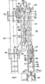
- the handling device 60 of a cluster of plugs 61 rests on stirrups 62 and 63 serving to fix the guide tube 24 to a wall of the pool 1.
- the two stirrups 62 and 63 are provided with 'pins 64 and 65 on which are hooked bases 66 and 67 integral with a frame 68 of the handling device 60.
- This frame 68 is formed of a base plate 69 arranged parallel to the wall of the pool, d 'a support plate 70 perpendicular to the base plate 69 and extending between the two bases 66 and 67, of a guide plate 71 extending parallel to the upper half of the support plate 70.
- control tube 75 On the support plate 70 is backed by a jack 72 whose head 73 is articulated on a slide 74 to which is secured a control tube 75 disposed parallel to the guide tube 24.
- the center distance between the control tube 75 and the guide tube 24 is identical to the distance between the baskets 21 and 22 of the carriage 4.
- the control tube 75 carries at the end a gripping head 76 formed of four columns arranged in a square, of which only the columns 77 and 78 are visible in FIG. 4, and held by two spacers 79 and 80.
- Each column carries at its lower end a conical end piece designated respectively by 81 and 82 for columns 77 and 78. These conical tips can be inserted in the upper part of an assembly 83.
- Columns 77, 78 are used to guide a cylinder 84 at the end of which is a mandrel 85 formed of a tube 86 inside which slides a telescopic pad 87.
- the tube 86 carries two diametrically opposite notches, only the notch 88 is visible in FIG. 4. These notches 88 have a cutout allowing attachment in a bayonet of the plug cluster 61 by its two wings 89 and 90.
- a shaft 91 disposed inside the control tube 75 makes it possible to animate the tube 86 of the mandrel 85 by an angle of rotation determined using a jack 92 connected to the end s tree 91.
- a pawl 93 the release of which is controlled by a jack 94.
- the handling device 60 operates in the following manner in its downward movement.
- the jack 94 unlocks the pawl 93 so that the jack 72 gives the gripping head 76 a downward movement.
- a control rod 95 raises a pawl 97 to allow the gripping head 76 to slide between the bars 77 and 78 to continue the downward movement and bring the tube 86 against the cluster of plugs 61 by compressing the buffer 87.
- a lug 98 integral with the shaft 91 is located in front of a notch 99 formed in the guide plate 71 to allow the rotation of the shaft 91 and of the cylinder 86 and thus allow the introduction of the wings 89 and 90 of the cluster of plugs 61 into the notches 88 of the cylinder 86.
- the cluster of plugs 61 is thus secured to the gripping head 76, the latter is reassembled by the jack 72. This cluster of plugs 61 can then be deposited on another assembly placed in another basket of the carriage 4 after movement of the carriage 4.
- the upward and downward movements of the gripping head 76 are ensured by a cable actuated by a winch situated above the water level of the swimming pool 1.
- This variant offers the advantage of avoiding the immersion of limit switches to know the exact position of the gripping head 76.
- Yet another variant consists in replacing the control rod 95 by a slide arranged around a conical end piece 82 to control the raising of the pawl 97 when the gripping head 76 is correctly positioned on the assembly 83.
Landscapes
- Physics & Mathematics (AREA)
- Engineering & Computer Science (AREA)
- Plasma & Fusion (AREA)
- General Engineering & Computer Science (AREA)
- High Energy & Nuclear Physics (AREA)
- Tents Or Canopies (AREA)
- Revetment (AREA)
- Refuge Islands, Traffic Blockers, Or Guard Fence (AREA)
- Warehouses Or Storage Devices (AREA)
- Monitoring And Testing Of Exchanges (AREA)
- Carriers, Traveling Bodies, And Overhead Traveling Cranes (AREA)
Applications Claiming Priority (2)
| Application Number | Priority Date | Filing Date | Title |
|---|---|---|---|
| EP84200704 | 1984-05-16 | ||
| EP84200704 | 1984-05-16 |
Publications (2)
| Publication Number | Publication Date |
|---|---|
| EP0163344A1 true EP0163344A1 (de) | 1985-12-04 |
| EP0163344B1 EP0163344B1 (de) | 1988-05-18 |
Family
ID=8192439
Family Applications (1)
| Application Number | Title | Priority Date | Filing Date |
|---|---|---|---|
| EP85200757A Expired EP0163344B1 (de) | 1984-05-16 | 1985-05-13 | Vorrichtung zur Verriegelung von Kontrollstäbe- und Zapfenkreuzvertauschungsaufstellung |
Country Status (4)
| Country | Link |
|---|---|
| EP (1) | EP0163344B1 (de) |
| AT (1) | ATE34480T1 (de) |
| DE (1) | DE3562831D1 (de) |
| ES (1) | ES8702060A1 (de) |
Cited By (2)
| Publication number | Priority date | Publication date | Assignee | Title |
|---|---|---|---|---|
| EP0250221A1 (de) * | 1986-06-19 | 1987-12-23 | Westinghouse Electric Corporation | Vorrichtung für das Beladen und Entladen von Containern |
| US4991427A (en) * | 1986-06-26 | 1991-02-12 | Westinghouse Electric Corp. | Bore mapping and surface time measurement system |
Citations (5)
| Publication number | Priority date | Publication date | Assignee | Title |
|---|---|---|---|---|
| DE1043530B (de) * | 1958-04-23 | 1958-11-13 | Maschf Augsburg Nuernberg Ag | Vorrichtung an Kernreaktor-Beschickungswagen zum genauen Anfahren der Beschickungsoeffnungen des Reaktors |
| GB919866A (en) * | 1960-09-02 | 1963-02-27 | Gen Electric Co Ltd | Improvements in or relating to nuclear reactor servicing machines |
| GB1002007A (en) * | 1962-12-11 | 1965-08-18 | Commissariat Energie Atomique | Nuclear reactor refuelling facility |
| FR2234637A1 (de) * | 1973-06-25 | 1975-01-17 | Westinghouse Electric Corp | |
| US4069766A (en) * | 1975-11-28 | 1978-01-24 | Combustion Engineering, Inc. | Fuel transfer machine |
-
1985
- 1985-05-13 EP EP85200757A patent/EP0163344B1/de not_active Expired
- 1985-05-13 DE DE8585200757T patent/DE3562831D1/de not_active Expired
- 1985-05-13 AT AT85200757T patent/ATE34480T1/de active
- 1985-05-16 ES ES543169A patent/ES8702060A1/es not_active Expired
Patent Citations (5)
| Publication number | Priority date | Publication date | Assignee | Title |
|---|---|---|---|---|
| DE1043530B (de) * | 1958-04-23 | 1958-11-13 | Maschf Augsburg Nuernberg Ag | Vorrichtung an Kernreaktor-Beschickungswagen zum genauen Anfahren der Beschickungsoeffnungen des Reaktors |
| GB919866A (en) * | 1960-09-02 | 1963-02-27 | Gen Electric Co Ltd | Improvements in or relating to nuclear reactor servicing machines |
| GB1002007A (en) * | 1962-12-11 | 1965-08-18 | Commissariat Energie Atomique | Nuclear reactor refuelling facility |
| FR2234637A1 (de) * | 1973-06-25 | 1975-01-17 | Westinghouse Electric Corp | |
| US4069766A (en) * | 1975-11-28 | 1978-01-24 | Combustion Engineering, Inc. | Fuel transfer machine |
Non-Patent Citations (3)
| Title |
|---|
| PATENS ABSTRACTS OF JAPAN, vol. 1, no. 122, 14. octobre 1977, page 3957 M 77; & JP - A - 52 59295 (TOKYO SHIBAURA DENKI K.K.) 16.05.1977 * |
| PATENTS ABSTRACTS OF JAPAN, vol. 3, no. 158, 25. décembre 1979, page 36 M 86; & JP - A - 54 134 288 (TOKYO SHIBAURA DENKI K.K.) 18.10.1979 * |
| PATENTS ABSTRACTS OF JAPAN, vol. 4, no. 13, 30. janvier 1980, page 96 M 90; & JP - A - 54 150 586 (FUJI DENKI SEIZO K.K.) 26.11.1979 * |
Cited By (2)
| Publication number | Priority date | Publication date | Assignee | Title |
|---|---|---|---|---|
| EP0250221A1 (de) * | 1986-06-19 | 1987-12-23 | Westinghouse Electric Corporation | Vorrichtung für das Beladen und Entladen von Containern |
| US4991427A (en) * | 1986-06-26 | 1991-02-12 | Westinghouse Electric Corp. | Bore mapping and surface time measurement system |
Also Published As
| Publication number | Publication date |
|---|---|
| ES8702060A1 (es) | 1986-12-16 |
| DE3562831D1 (en) | 1988-06-23 |
| ES543169A0 (es) | 1986-12-16 |
| ATE34480T1 (de) | 1988-06-15 |
| EP0163344B1 (de) | 1988-05-18 |
Similar Documents
| Publication | Publication Date | Title |
|---|---|---|
| FR2549029A1 (fr) | Elevateur comportant au moins un mat telescopique | |
| FR2540548A1 (fr) | Mecanisme a coins de retenue, utilisable comme elevateur ou comme dispositif de retenue dans un appareil de forage | |
| FR2479135A1 (fr) | Dispositif a barillet pour l'emport et le lancement de bouees a bord d'aeronef | |
| FR2588689A1 (fr) | Machine de manutention d'assemblage combustible nucleaire et procede de chargement de reacteur en comportant application | |
| EP0163344B1 (de) | Vorrichtung zur Verriegelung von Kontrollstäbe- und Zapfenkreuzvertauschungsaufstellung | |
| WO1988000451A1 (fr) | Lit d'examen pour appareil de rmn ou de tomodensitometrie | |
| FR2758844A1 (fr) | Appareil pour la mise en place de plaques de plafond | |
| EP0685599B1 (de) | System zum Transportieren von mindestens zwei Brückenteilen durch ein Fahrzeug zur Überwindung von Gräben und System zum Ablegen dieser Teile über die Gräben durch das Fahrzeug | |
| EP0063985B1 (de) | Vorrichtung zum Positionieren eines Gerätes in den Öffnungen einer Rohrplatte | |
| EP0278879A1 (de) | Maschine zur automatischen Herstellung von Fleisch- und/oder Gemüsespiessen | |
| CH420987A (fr) | Installation de transport d'objets, notamment à travers un four | |
| CH619390A5 (en) | Transfer machine for assembling and/or machining components | |
| FR2691480A1 (fr) | Procédé et dispositif pour introduire et extraire des bobines de fil et des bobinots sur des machines textiles. | |
| FR2843153A1 (fr) | Dispositif de couverture provisoire de piscine et piscine equipee dudit dispositif | |
| EP0040154A1 (de) | Maschine zum Be- oder Entladen von Behältern für den Transport ausgerichteter Gegenstände | |
| EP0248251A1 (de) | Automatisierte Vorrichtung zum Ausmauern eines Gefässes | |
| FR2577865A1 (fr) | Dispositif de relevage de la charpente supportant la couverture d'un vehicule de transport | |
| EP0360651B1 (de) | Sicherheitseinrichtung für eine Verschubbetätigung eines Kernbrennelement-Förderwagens | |
| FR2602119A1 (fr) | Machine automatique pour le chargement et le dechargement des plateaux des cadres a rayons dans le traitement des viandes en general | |
| BE1001752A3 (fr) | Dispositif d'accouplement pour remplacer des outillages sur la chape d'un engin de levage et magasin faisant application de ce dispositif. | |
| FR2659637A1 (fr) | Dispositif de levage pour conteneurs. | |
| SU933936A1 (ru) | Устройство дл перемещени свечей бурильных труб | |
| EP2023778B1 (de) | Sichere basis für eine matte zum windelwechseln | |
| EP0528736B1 (de) | Vorrichtung zum Transfer von Scheiben, insbesondere Silicon-Scheiben | |
| FR2527826A1 (fr) | Dispositif de commande des barres absorbantes dans un systeme de pilotage d'un reacteur nucleaire |
Legal Events
| Date | Code | Title | Description |
|---|---|---|---|
| PUAI | Public reference made under article 153(3) epc to a published international application that has entered the european phase |
Free format text: ORIGINAL CODE: 0009012 |
|
| AK | Designated contracting states |
Designated state(s): AT BE CH DE FR GB IT LI LU NL SE |
|
| 17P | Request for examination filed |
Effective date: 19860522 |
|
| 17Q | First examination report despatched |
Effective date: 19870601 |
|
| RAP1 | Party data changed (applicant data changed or rights of an application transferred) |
Owner name: ACEC, SOCIETE ANONYME |
|
| GRAA | (expected) grant |
Free format text: ORIGINAL CODE: 0009210 |
|
| AK | Designated contracting states |
Kind code of ref document: B1 Designated state(s): AT BE CH DE FR GB IT LI LU NL SE |
|
| REF | Corresponds to: |
Ref document number: 34480 Country of ref document: AT Date of ref document: 19880615 Kind code of ref document: T |
|
| REF | Corresponds to: |
Ref document number: 3562831 Country of ref document: DE Date of ref document: 19880623 |
|
| GBT | Gb: translation of ep patent filed (gb section 77(6)(a)/1977) | ||
| ITF | It: translation for a ep patent filed | ||
| PLBE | No opposition filed within time limit |
Free format text: ORIGINAL CODE: 0009261 |
|
| STAA | Information on the status of an ep patent application or granted ep patent |
Free format text: STATUS: NO OPPOSITION FILED WITHIN TIME LIMIT |
|
| PG25 | Lapsed in a contracting state [announced via postgrant information from national office to epo] |
Ref country code: GB Effective date: 19890513 Ref country code: AT Effective date: 19890513 |
|
| 26N | No opposition filed | ||
| PG25 | Lapsed in a contracting state [announced via postgrant information from national office to epo] |
Ref country code: LU Free format text: LAPSE BECAUSE OF NON-PAYMENT OF DUE FEES Effective date: 19890531 |
|
| PG25 | Lapsed in a contracting state [announced via postgrant information from national office to epo] |
Ref country code: NL Effective date: 19891201 |
|
| GBPC | Gb: european patent ceased through non-payment of renewal fee | ||
| NLV4 | Nl: lapsed or anulled due to non-payment of the annual fee | ||
| PG25 | Lapsed in a contracting state [announced via postgrant information from national office to epo] |
Ref country code: DE Effective date: 19900201 |
|
| PGFP | Annual fee paid to national office [announced via postgrant information from national office to epo] |
Ref country code: FR Payment date: 19910508 Year of fee payment: 7 |
|
| PGFP | Annual fee paid to national office [announced via postgrant information from national office to epo] |
Ref country code: SE Payment date: 19910513 Year of fee payment: 7 |
|
| PGFP | Annual fee paid to national office [announced via postgrant information from national office to epo] |
Ref country code: CH Payment date: 19910515 Year of fee payment: 7 |
|
| PGFP | Annual fee paid to national office [announced via postgrant information from national office to epo] |
Ref country code: BE Payment date: 19920526 Year of fee payment: 8 |
|
| PG25 | Lapsed in a contracting state [announced via postgrant information from national office to epo] |
Ref country code: SE Free format text: THE PATENT HAS BEEN ANNULLED BY A DECISION OF A NATIONAL AUTHORITY Effective date: 19920530 |
|
| PG25 | Lapsed in a contracting state [announced via postgrant information from national office to epo] |
Ref country code: LI Effective date: 19920531 Ref country code: CH Effective date: 19920531 |
|
| PG25 | Lapsed in a contracting state [announced via postgrant information from national office to epo] |
Ref country code: FR Effective date: 19930129 |
|
| REG | Reference to a national code |
Ref country code: CH Ref legal event code: PL |
|
| REG | Reference to a national code |
Ref country code: FR Ref legal event code: ST |
|
| PG25 | Lapsed in a contracting state [announced via postgrant information from national office to epo] |
Ref country code: BE Effective date: 19930531 |
|
| BERE | Be: lapsed |
Owner name: S.A. ACEC Effective date: 19930531 |
|
| EUG | Se: european patent has lapsed |
Ref document number: 85200757.4 Effective date: 19921204 |