EP0163568A1 - Gerät zum Einsetzen von haarnadelförmigen Federn auf Platten, insbesondere für Roste einer Brennstoffanordnung - Google Patents
Gerät zum Einsetzen von haarnadelförmigen Federn auf Platten, insbesondere für Roste einer Brennstoffanordnung Download PDFInfo
- Publication number
- EP0163568A1 EP0163568A1 EP85400918A EP85400918A EP0163568A1 EP 0163568 A1 EP0163568 A1 EP 0163568A1 EP 85400918 A EP85400918 A EP 85400918A EP 85400918 A EP85400918 A EP 85400918A EP 0163568 A1 EP0163568 A1 EP 0163568A1
- Authority
- EP
- European Patent Office
- Prior art keywords
- spring
- springs
- plate
- clamp
- branches
- Prior art date
- Legal status (The legal status is an assumption and is not a legal conclusion. Google has not performed a legal analysis and makes no representation as to the accuracy of the status listed.)
- Granted
Links
Images


Classifications
-
- B—PERFORMING OPERATIONS; TRANSPORTING
- B23—MACHINE TOOLS; METAL-WORKING NOT OTHERWISE PROVIDED FOR
- B23P—METAL-WORKING NOT OTHERWISE PROVIDED FOR; COMBINED OPERATIONS; UNIVERSAL MACHINE TOOLS
- B23P19/00—Machines for simply fitting together or separating metal parts or objects, or metal and non-metal parts, whether or not involving some deformation; Tools or devices therefor so far as not provided for in other classes
-
- B—PERFORMING OPERATIONS; TRANSPORTING
- B23—MACHINE TOOLS; METAL-WORKING NOT OTHERWISE PROVIDED FOR
- B23P—METAL-WORKING NOT OTHERWISE PROVIDED FOR; COMBINED OPERATIONS; UNIVERSAL MACHINE TOOLS
- B23P21/00—Machines for assembling a multiplicity of different parts to compose units, with or without preceding or subsequent working of such parts, e.g. with program control
-
- B—PERFORMING OPERATIONS; TRANSPORTING
- B23—MACHINE TOOLS; METAL-WORKING NOT OTHERWISE PROVIDED FOR
- B23P—METAL-WORKING NOT OTHERWISE PROVIDED FOR; COMBINED OPERATIONS; UNIVERSAL MACHINE TOOLS
- B23P19/00—Machines for simply fitting together or separating metal parts or objects, or metal and non-metal parts, whether or not involving some deformation; Tools or devices therefor so far as not provided for in other classes
- B23P19/04—Machines for simply fitting together or separating metal parts or objects, or metal and non-metal parts, whether or not involving some deformation; Tools or devices therefor so far as not provided for in other classes for assembling or disassembling parts
-
- G—PHYSICS
- G21—NUCLEAR PHYSICS; NUCLEAR ENGINEERING
- G21C—NUCLEAR REACTORS
- G21C3/00—Reactor fuel elements and their assemblies; Selection of substances for use as reactor fuel elements
- G21C3/30—Assemblies of a number of fuel elements in the form of a rigid unit
- G21C3/32—Bundles of parallel pin-, rod-, or tube-shaped fuel elements
- G21C3/34—Spacer grids
- G21C3/3424—Fabrication of spacer grids
-
- Y—GENERAL TAGGING OF NEW TECHNOLOGICAL DEVELOPMENTS; GENERAL TAGGING OF CROSS-SECTIONAL TECHNOLOGIES SPANNING OVER SEVERAL SECTIONS OF THE IPC; TECHNICAL SUBJECTS COVERED BY FORMER USPC CROSS-REFERENCE ART COLLECTIONS [XRACs] AND DIGESTS
- Y02—TECHNOLOGIES OR APPLICATIONS FOR MITIGATION OR ADAPTATION AGAINST CLIMATE CHANGE
- Y02E—REDUCTION OF GREENHOUSE GAS [GHG] EMISSIONS, RELATED TO ENERGY GENERATION, TRANSMISSION OR DISTRIBUTION
- Y02E30/00—Energy generation of nuclear origin
- Y02E30/30—Nuclear fission reactors
-
- Y—GENERAL TAGGING OF NEW TECHNOLOGICAL DEVELOPMENTS; GENERAL TAGGING OF CROSS-SECTIONAL TECHNOLOGIES SPANNING OVER SEVERAL SECTIONS OF THE IPC; TECHNICAL SUBJECTS COVERED BY FORMER USPC CROSS-REFERENCE ART COLLECTIONS [XRACs] AND DIGESTS
- Y10—TECHNICAL SUBJECTS COVERED BY FORMER USPC
- Y10T—TECHNICAL SUBJECTS COVERED BY FORMER US CLASSIFICATION
- Y10T29/00—Metal working
- Y10T29/53—Means to assemble or disassemble
- Y10T29/531—Nuclear device
Definitions
- the invention relates to the installation of hairpin springs intended to support the fuel rods in fuel assembly spacer grids.
- Very frequently used fuel assemblies include a bundle of fuel rods (each constituted by a stack of pellets in a sealed sheath) held in a structure.
- the latter comprises grids distributed along the assembly and constituted by plates arranged in two orthogonal directions, to define cells the major part of which at least is crossed by pencils.
- Each of these cells is provided with means based on the pencil which crosses the cell to support it.
- the springs generally have a hairpin shape, with two branches.
- it is necessary to provide in the same grid several types of spring because the grid has edges and that often some cells are occupied by elements other than rods, for example by guide tubes.
- One type will frequently have two identical branches, while another type will have different branches.
- These springs are first inserted, then definitively secured plates by welding the two branches one on the other at well defined points, between which there are windows formed in the grid plate.
- each spring is a delicate operation: it is necessary to locate them precisely so as not to pinch them on the plates during the welding operation, and to avoid any contamination.
- the mounting of the springs and their welding have been carried out manually, which constitutes a long and painful operation, susceptible moreover to give rise to errors when springs of different types must be placed in well-defined zones. of the brochure.
- Patent application FR-A-2 535 101 by the applicant also describes a method and a device for fitting hairpin springs and for welding.
- the plate is moved step by step to successively bring all the zones of the plate to be provided, with springs in an insertion entwining where a spring is slid in place by displacement according to a, near orientation from the plane of the insert, in a direction perpendicular to the length of the insert.
- the latter must be covered with a mask during insertion. The mask is then removed to allow spot welding of the branches of the spring through the windows.
- the invention aims to provide a device for installing springs which responds better than those previously known to the requirements of practice, in particular in that it allows a particularly rapid and safe installation of the springs.
- the invention proposes in particular a device for inserting hairpin springs with two branches straddling a plate provided with windows making it possible to locally weld the branches against each other, characterized in that it comprises means for receiving a plate both in a vertical position, for moving it lengthwise, for bringing it into successive positions each corresponding to the arrival of one of the spring receiving zones at a location insertion, centering means and temporary holding of the wafer in said successive positions; means for guiding the springs towards a setting location; and a clamp intended to grip each spring in turn by the end of one of its branches, associated with means for moving the clamp in a plane perpendicular to the wafer following an introduction path of the other branch of the spring in the plate.
- the device advantageously comprises means of electrical welding by clamp acting on the spring while the corresponding reception area is at the insertion location.
- these clamp welding means are provided so as not to join the branches of the spring only through one of the two windows which are generally provided.
- the means for moving the wafer lengthwise are then associated with an additional welding station, intended to weld the two arms of the wafer to each other through the second window.
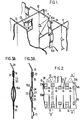
- This grid 10 is constituted by plates 11, generally in zirconium-based alloy called "zircaloy”, assembled half-iron and welded at their connection points 12.
- Each of the plates 11 has bosses 13 for supporting fuel rods (not shown) and various openings cooperating with the springs intended to apply the rods to the bosses.
- Figure 1 appear only double springs 15A which are inserted in the notches 14 of the plates opening onto one of the edges.
- each of the springs 15A can be put in place by sliding its branches on either side of the plate 11 until the upper loop of the spring comes into contact with the plate, at the bottom of the notch 14.
- Windows 19 made in the plate make it possible to fix the two spring branches directly to each other using a welding point 20.
- the simple spring 15B shown in Figure 38 has an asymmetrical constitution. Its branch 22 is similar to the branches of the spring 15A.
- the other branch 23 is designed so as to constitute a ball joint delimited by two folds 24 capable of coming into contact with the branch 22 through openings 25 in the wafer, to avoid transmitting the compression forces thereof.
- the two branches of the spring 1 ' 5B are welded to each other through windows 19 on the finished grid. But the loop does not come to be placed at the bottom of the notch, but in an extension of the upper window 19, formed by one of the bosses 13. It is therefore not possible to directly pass the branches 22 and 23 from the side and on the other side of the brochure.
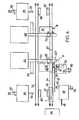
- the assembly and welding device can be viewed as consisting of several fixed work stations, ensuring successive operations, and a mechanism for transporting the wafers to be fitted and for presenting the wafers to successive posts.
- the transport mechanism is provided for transporting the plates 11 on individual modules 32 which hold them in the vertical position.
- This mechanism includes a feed path 34, a return path 36 parallel to the previous one and two transfer mechanisms 38 and 39.
- Each track consists of two belts 40 supported by idler pulleys and drive pulleys driven by a not shown electric stepper motor.
- the module transfer mechanism 38 includes a step-up mechanism 42 framing the initial part of the track 34 and making it possible to lift a module above the track or, on the contrary, to deposit it on the track.
- Each module 32 (FIG. 6A) comprises a slot for receiving the lower part of a plate 11 and retractable pins distributed at the same pitch as the areas for receiving the springs, seventeen for example.
- the operator projects those of the pins which correspond to the zones to be fitted with a spring of a specific type.
- the first work station placed on the feed path 34 is constituted by a station for centering and holding wafers between clamping jaws, station associated with a welding machine 45 and with a supply and insertion assembly.
- springs The spring supply assembly comprises a spring magazine 46 intended to receive spring bars, a shear 48 which cuts the springs and a clamp 52 actuated by a jack 50 which brings them one by one on a vibrating rail 54 of guiding the springs to a gripping location. It further comprises a manipulator 56 having a clamp 58 intended to grip each spring 15A or 15B in turn and to place it on the plate 11 while the latter is immobilized so that the zone to be equipped is in a fixed and well-determined position of insertion.
- the handling clamp 58 can be moved vertically by a jack 60 and horizontally, transversely to the plane of the wafer 11, by a jack 62.
- the welding machine 45 may be of the type with electric spot welding tongs described in patent application FR-A-2 535 101.
- FIG. 4 likewise shows the beam 64 carrying welding jaws 66 which can be moved apart and brought together.
- a jack 67 ( Figure 5) allows the jaws to be brought together to clamp the branches of a spring against one another and to release them.
- the welding machine 45 is designed to perform only the upper fixing weld of each spring 15A or 158. Thus, the rate of equipment of a wafer is not delayed by the time necessary for two successive welding operations.
- a second welding machine 68 similar to the first, also associated with a station 70 for temporary clamping of the module, is placed downstream of the first on the supply track 34.
- a cylinder of the welding machine 68 makes it possible to tighten one against the other, through the lower window 19, the branches of the spring located in a welding location between the electric welding jaws 72.
- a jack 74 is provided for indexing step by step the module placed at station 70.
- the transfer mechanism 39 placed downstream of the station 70 is intended to pass each module 32, carrying an equipped plate, from track 34 to track 36.
- This transfer mechanism comprises a handling assembly 78 provided with a clamp 76 whose horizontal movements are controlled by a jack 40.
- the clamp 76 allows the module 32 to be gripped on a lifting and lowering station 82 (planing station) and to deposit it on a similar planing station 84 associated with the track. return 36.
- the station 84 allows the module 32 to be placed on the return path 36 of the fitted wafers.
- the return path brings the module 32 near the handling station 44 where it lands on a planing device 86 similar to the devices 82 and 84.
- the device 86 belongs to the transfer mechanism 38 comprising a handling assembly 88 similar to the 'assembly 78 and also having a clamp 90 and a cylinder 92.
- the clamp 90 allows to horizontally move the module 32 and to position it on the mechanism 42, after release of the latter by a module 32 equipped with a blank plate.
- the operator placed at the handling station 44 can then grasp the fully equipped wafer brought by the module 32, extract this plate and replace it with a plate to be fitted.
- This station comprises a fixed frame on which a left jaw 94 (Figure 6A) and a right jaw 96 ( Figure 6B) are mounted by means of respective tilt axes 98 and 100 parallel to the direction F of movement of the module 32 on track 34.
- the jaws are shown in phantom in their retracted position, allowing the movement of the module 32, and in solid lines in clamping position.
- the chassis carries a sensor (not shown) for detecting the arrival of a protruding pin on the module 32 at the location of the spring insertion.
- the jaw 94 is provided with a pin 101 for blocking the module 32 when the jaw is closed. This pin cooperates with a bar 102 formed in the module 32 in order to present an interchangeable hardened surface.
- the device for centering the wafer 11 at the insertion location comprises a centering finger 103 which a reciprocating mechanism 105 makes it possible to move the chassis between a retracted position, where it is shown in FIG. 5 , and an advanced position, where the pin engages in a housing 104 located opposite, through a window of the wafer.
- the step-by-step indexing of the module after each mounting of a spring is controlled by a jack 107.
- FIG. 6A shows a wedge 106 carried by a flange 110 fixed to the chassis by screws 108.
- the flange is only placed for equipping a plate with asymmetric springs 158.
- the wedge 106 which it carries, located at right of the location of the plate 11 to be fitted, guides the springs during their insertion, as will be seen below. Indeed, the wedge gives to the branch of the springs 158 an orientation allowing them to be introduced into the openings located below the bosses 13.
- the flange 110 is removed during the installation of the springs 15A which are positioned astride the notches 14 of the wafer 11.
- the jaws 94 and 96 are provided with return springs in the open position (112 in FIG. 6A). Their closing is controlled by respective pushers actuated by cylinder and cam (114 in Figure 6A).
- the main components of the manipulator 56 for supplying and inserting the springs appear in FIG. 7, where the spring shown is a double spring 15A.
- These components include a carriage 116 which slides on vertical columns 118 under the action of a jack 120 ( Figure 5).
- the carriage 116 carries a separator 122 which makes it possible to lift one spring vertically at a time from the vibrating guide rail 54 to a level of recovery by the clamp 58.
- a fixed cover 124 avoids lifting two springs at the same time.
- the jack 60 makes it possible to move the clamp 58 from the low position, where it is shown in solid lines in FIG. 7 and can grasp a spring, at the high position indicated at 58a. In this position of the clamp, the spring 15A is at a level just higher than that of the plate 11. The jack 62 then makes it possible to move the clamp horizontally to bring it to position 58b. The spring 15A is then located just above the location of the plate where it is to be introduced. The jack 60 makes it possible to lower the clamp at 58c to introduce the spring.
- FIG. 8 shows in solid lines successive positions 58. 58A. 58b and 58s taken by the clamp, which can be compared with those (indicated in dashed lines) when inserting the springs 15A.
- the operator firstly provides a module 32 with a plate to be equipped and programs the pins according to the locations where springs of a determined type must be introduced. A spring bar of the type to be inserted is placed on the magazine 46.
- the shears 48 individually detach each spring which the clamp 52 places astride the vibrating guide rail 54.
- the module, placed by the operator on the mechanism 42, is lowered by the latter on the supply track 34.
- the motor belt drive 40 drives the module to the centering and holding station.
- the centering pin 103 advances and exactly centers the plate.
- the first articulated jaw 94 is applied to the left face of the wafer 11.
- the jaw 96 is, in turn, actuated and applied to the right face of the wafer 11.
- the centering finger 103 moves back.
- the clamp 58 grasps a spring to be inserted and introduces it. When the plate is to be fitted with simple springs 15B, the shim 106 has been previously put in place.
- the clamp 58 then raises the spring only to the position corresponding to the altitude of the opening under the bosses 13 of the plate 11.
- the combined action of the clamp 58 and the wedge 106 directs the spring 15B obliquely relative to the plate, which allows the branch of the spring not held by the clamp 58 to slide into the opening when the clamp descends (Figure 8).
- the beam 64 of the welding machine is moved to the left over the distance St ( Figure 5) by its jack 124 ( Figure 4).
- the jaws 66 are brought together so that the welding electrodes are applied to the branches and press them against one another.
- the clamp 58 is retracted.
- the two branches are welded to each other at their upper part through the window 19.
- the successive springs are thus put in place and welded.
- the module 32 is advanced by the jack 107 which controls a rod acting on a path formed by teeth machined on the underside of the module 32.
- the operation of the jack 107, and therefore the advance of the module of the number of steps required, is controlled by a detector which causes the module to stop each time a peg placed on the side of the module appears.
- the module is driven by the belts 40 to the second clamping station 70.
- the welding machine 68 then performs a second weld on each spring , through the lower window 19 of the wafer, which implies that the welding electrodes carried by the jaws 72 are at a level lower than those of the first machine 45.
- the module 32 is taken over by the belts 40 and travels the rest of the feed path 34, then the return path 36.
- the transfer mechanism 38 brings the module back onto the up-down mechanism 42 where the operator extracts the fitted board and replaces it with a blank board.
- the wafers are thus continuously equipped, several modules possibly being simultaneously on tracks 34 and 36 by constituting a noria. Programming using module pawns allows to carry out, on successive plates, distributions of different springs.
- the device according to the invention allows, thanks to the programming authorized by the pins of the modules, to repair a wafer by replacing a spring whose welding is defective.
- clamping station 70 makes it possible to provide, in the individual modules 32, slots for receiving the wafers 11 having a length greater than the length of the wafer, in order to facilitate the insertion of the latter. An excess of 0.5 mm in length is sufficient for the operator to easily slide the plates into the slots.
- the clamping station 70 may be provided with means for indexing the lower part of the branches of each spring relative to the plate.
- Figures 9 to 12 show a constitution possible of these means.
- FIG. 9 shows a module 32 comprising a positioning device constituted by a stop 132 and by a spring plunger 131.
- the force exerted by the spring 131 can be weak: it only completes the natural bearing of the plate 11 on the stop 132 when the module 32 stops at the temporary clamping station 70.
- the spring plunger 131 also ensures the repositioning of the plate after welding.
- the station 70 comprises a stop strip 203 against which the module 32 comes to bear when it is at the station 70.
- the fixed parts have not been shown, nor have the welding members except for welding tongs 72.
- the indexing means comprise two clamps 140 and 141 having a similar constitution.
- Each of the pliers includes a long jaw 142 and a short jaw 143 ( Figure 10).
- the clamps are actuated by a mechanism mounted on the installation chassis. This mechanism comprises two plates 146 and 147 mounted on runners 148 so as to be able to move away from and towards each other. The bringing together of the slides so as to bring the clamps 140 and 141 which they bear in contact with the plate 11 is ensured by a spring 154 ( Figure 12).
- the spacing of the plates is controlled by a cam 150 actuated by a jack 151.
- the plates 146 and 147 carry rollers 155 resting on the cam.
- the height of the clamps 140 and 141 is adjustable using threaded rods 149 ( Figure 11). Their maximum spacing is adjustable using other threaded rods 156 ( Figure 11).
- the long jaw 142 of the pliers constitutes a jaw extending over the greater part of the length of a spring 15.
- the face of the jaw 142 intended to come into contact with the spring has a slope relative to the vertical.
- a device has been produced in which the difference in thickness between the upper end of the jaw 142 and the lower end is 0.15 mm, the lower end being the least thick.
- the centering of a spring 15 is carried out after stopping the module 32 and abutting with the aid of the strip 203 and before welding. For this, the jack 151 is put into action to authorize the closing of the clamps 140 and 141 under the action of the spring 154.
- the closing of the clamp pushes the upper loop of the spring 15 in abutment against one of the edges of the window 14.
- the plate 11 is itself driven backwards and leaves its abutment.
- the lower part of the jaw 142 cooperates with the short jaw 113, each clamp thus holding one of the branches of the spring 15 to the right of the window 19.
- the welding clamps 72 located under the centering clamps 140 and 141, are then put into action to achieve the low weld.
- the clamps 140 and 141 are opened by actuating the jack 151.
- the spring plunger 131 then pushes the plate 11 to bring it into its stop position.
Landscapes
- Engineering & Computer Science (AREA)
- Mechanical Engineering (AREA)
- Physics & Mathematics (AREA)
- Plasma & Fusion (AREA)
- General Engineering & Computer Science (AREA)
- High Energy & Nuclear Physics (AREA)
- Butt Welding And Welding Of Specific Article (AREA)
- Automatic Assembly (AREA)
- Manipulator (AREA)
Applications Claiming Priority (2)
| Application Number | Priority Date | Filing Date | Title |
|---|---|---|---|
| FR8407220A FR2564020B1 (fr) | 1984-05-10 | 1984-05-10 | Dispositif de mise en place de ressorts en epingle a cheveux sur des plaquettes, notamment pour grilles d'assemblage de combustible |
| FR8407220 | 1984-05-10 |
Publications (2)
| Publication Number | Publication Date |
|---|---|
| EP0163568A1 true EP0163568A1 (de) | 1985-12-04 |
| EP0163568B1 EP0163568B1 (de) | 1988-04-27 |
Family
ID=9303843
Family Applications (1)
| Application Number | Title | Priority Date | Filing Date |
|---|---|---|---|
| EP85400918A Expired EP0163568B1 (de) | 1984-05-10 | 1985-05-10 | Gerät zum Einsetzen von haarnadelförmigen Federn auf Platten, insbesondere für Roste einer Brennstoffanordnung |
Country Status (9)
| Country | Link |
|---|---|
| US (1) | US4646431A (de) |
| EP (1) | EP0163568B1 (de) |
| JP (1) | JPH0626772B2 (de) |
| KR (1) | KR930003341B1 (de) |
| DE (1) | DE3562330D1 (de) |
| ES (1) | ES8700999A1 (de) |
| FR (1) | FR2564020B1 (de) |
| YU (1) | YU77785A (de) |
| ZA (1) | ZA853565B (de) |
Cited By (5)
| Publication number | Priority date | Publication date | Assignee | Title |
|---|---|---|---|---|
| FR2610445A1 (fr) * | 1987-01-29 | 1988-08-05 | Framatome Sa | Ressort en epingle a cheveux pour assemblage de combustible nucleaire et grille d'assemblage comportant de tels ressorts |
| EP0372787A3 (de) * | 1988-12-02 | 1990-08-22 | General Electric Company | Apparat zur automatischen Formgebung |
| EP0372785A3 (de) * | 1988-12-02 | 1990-08-22 | General Electric Company | Apparat zum automatisierten Zusammenbau |
| GB2271946A (en) * | 1992-10-29 | 1994-05-04 | Westinghouse Electric Corp | Method of making a fuel assembly lattice member and the lattice member made by such method |
| FR2802330A1 (fr) * | 1999-12-13 | 2001-06-15 | Franco Belge Combustibles | Dispositif et procede de montage d'une grille-entretoise d'un assemblage de combustible pour un reacteur nucleaire |
Families Citing this family (2)
| Publication number | Priority date | Publication date | Assignee | Title |
|---|---|---|---|---|
| FR2646548B1 (fr) * | 1989-04-28 | 1993-11-26 | Framatome | Grille a ressorts de maintien pour assemblage combustible nucleaire |
| KR100680483B1 (ko) * | 2005-12-16 | 2007-02-08 | 두산중공업 주식회사 | 핵연료 이송기의 수평수직 전환장치 |
Citations (7)
| Publication number | Priority date | Publication date | Assignee | Title |
|---|---|---|---|---|
| US2629296A (en) * | 1948-02-10 | 1953-02-24 | Solo Products Corp | Machine for automatically carding curlers |
| US3781967A (en) * | 1972-09-25 | 1974-01-01 | R Fisher | Buckle assembly machine and method |
| EP0022419A1 (de) * | 1979-06-26 | 1981-01-14 | Bernard Petit | Apparat und Verfahren zum automatischen Anbringen von Wäscheklammern des Federklammer-Typs auf Karten |
| FR2474229A1 (fr) * | 1980-01-22 | 1981-07-24 | Commissariat Energie Atomique | Grille entretoise pour assemblage combustible de reacteur nucleaire |
| FR2526699A1 (fr) * | 1982-05-14 | 1983-11-18 | Gnb Batteries Inc | Appareil et procede pour realiser la commande programmee de fonctions de travail, notamment pour le soudage d'elements de batterie |
| EP0108673A1 (de) * | 1982-10-22 | 1984-05-16 | SOCIETE COGEMA, FRAMATOME et URANIUM PECHINEY | Verfahren und Gerät zum Einsetzen von haarnadelförmigen Federn auf Platten, insbesondere für Roste einer Brennstoffanordnung |
| EP0043208B1 (de) * | 1980-06-18 | 1986-09-03 | Hitachi, Ltd. | Bearbeitungs- und Montagesystem |
Family Cites Families (3)
| Publication number | Priority date | Publication date | Assignee | Title |
|---|---|---|---|---|
| SU386110A1 (ru) * | 1971-06-17 | 1973-06-14 | УСТРОЙСТВО дл СБОРКИ МЕТАЛЛИЧЕСКИХ РЕШЕТЧАТЫХ СТРОИТЕЛЬНЫХ ЭЛЕМЕНТОВ ТИПА ЛЕСТНИЦ | |
| US4079497A (en) * | 1976-07-28 | 1978-03-21 | Jernigan Emory J | Method of making substantially impenetrable members |
| FR2533352B1 (fr) * | 1982-09-16 | 1988-08-12 | Fragema Framatome & Cogema | Procede et dispositif d'assemblage de plaquettes de grilles |
-
1984
- 1984-05-10 FR FR8407220A patent/FR2564020B1/fr not_active Expired
-
1985
- 1985-05-10 YU YU00777/85A patent/YU77785A/xx unknown
- 1985-05-10 ZA ZA853565A patent/ZA853565B/xx unknown
- 1985-05-10 JP JP60099456A patent/JPH0626772B2/ja not_active Expired - Lifetime
- 1985-05-10 DE DE8585400918T patent/DE3562330D1/de not_active Expired
- 1985-05-10 EP EP85400918A patent/EP0163568B1/de not_active Expired
- 1985-05-10 US US06/732,548 patent/US4646431A/en not_active Expired - Lifetime
- 1985-05-10 KR KR1019850003180A patent/KR930003341B1/ko not_active Expired - Fee Related
- 1985-05-10 ES ES543581A patent/ES8700999A1/es not_active Expired
Patent Citations (7)
| Publication number | Priority date | Publication date | Assignee | Title |
|---|---|---|---|---|
| US2629296A (en) * | 1948-02-10 | 1953-02-24 | Solo Products Corp | Machine for automatically carding curlers |
| US3781967A (en) * | 1972-09-25 | 1974-01-01 | R Fisher | Buckle assembly machine and method |
| EP0022419A1 (de) * | 1979-06-26 | 1981-01-14 | Bernard Petit | Apparat und Verfahren zum automatischen Anbringen von Wäscheklammern des Federklammer-Typs auf Karten |
| FR2474229A1 (fr) * | 1980-01-22 | 1981-07-24 | Commissariat Energie Atomique | Grille entretoise pour assemblage combustible de reacteur nucleaire |
| EP0043208B1 (de) * | 1980-06-18 | 1986-09-03 | Hitachi, Ltd. | Bearbeitungs- und Montagesystem |
| FR2526699A1 (fr) * | 1982-05-14 | 1983-11-18 | Gnb Batteries Inc | Appareil et procede pour realiser la commande programmee de fonctions de travail, notamment pour le soudage d'elements de batterie |
| EP0108673A1 (de) * | 1982-10-22 | 1984-05-16 | SOCIETE COGEMA, FRAMATOME et URANIUM PECHINEY | Verfahren und Gerät zum Einsetzen von haarnadelförmigen Federn auf Platten, insbesondere für Roste einer Brennstoffanordnung |
Cited By (9)
| Publication number | Priority date | Publication date | Assignee | Title |
|---|---|---|---|---|
| FR2610445A1 (fr) * | 1987-01-29 | 1988-08-05 | Framatome Sa | Ressort en epingle a cheveux pour assemblage de combustible nucleaire et grille d'assemblage comportant de tels ressorts |
| EP0280595A3 (en) * | 1987-01-29 | 1988-09-14 | Framatome | Bracket leaf spring for a nuclear-fuel assembly, and assembly spacer grid comprising such a spring |
| EP0372787A3 (de) * | 1988-12-02 | 1990-08-22 | General Electric Company | Apparat zur automatischen Formgebung |
| EP0372785A3 (de) * | 1988-12-02 | 1990-08-22 | General Electric Company | Apparat zum automatisierten Zusammenbau |
| GB2271946A (en) * | 1992-10-29 | 1994-05-04 | Westinghouse Electric Corp | Method of making a fuel assembly lattice member and the lattice member made by such method |
| GB2271946B (en) * | 1992-10-29 | 1996-02-28 | Westinghouse Electric Corp | Method of making a fuel assembly lattice member and the lattice member made by such method |
| FR2802330A1 (fr) * | 1999-12-13 | 2001-06-15 | Franco Belge Combustibles | Dispositif et procede de montage d'une grille-entretoise d'un assemblage de combustible pour un reacteur nucleaire |
| WO2001045114A1 (fr) * | 1999-12-13 | 2001-06-21 | Societe Franco-Belge De Fabrication De Combustible - Fbfc | Dispositif et procede de montage d'une grille-entretoise d'un assemblage de combustible pour un reacteur nucleaire |
| US6621885B2 (en) | 1999-12-13 | 2003-09-16 | Societe Franco-Belge De Fabrication De Combustible-Fbfc | Apparatus and a method for assembling a spacer grid of a fuel assembly for a nuclear reactor |
Also Published As
| Publication number | Publication date |
|---|---|
| JPH0626772B2 (ja) | 1994-04-13 |
| EP0163568B1 (de) | 1988-04-27 |
| ES8700999A1 (es) | 1986-12-01 |
| ZA853565B (en) | 1986-07-30 |
| FR2564020B1 (fr) | 1986-10-24 |
| FR2564020A1 (fr) | 1985-11-15 |
| KR930003341B1 (ko) | 1993-04-26 |
| KR850008427A (ko) | 1985-12-16 |
| ES543581A0 (es) | 1986-12-01 |
| DE3562330D1 (en) | 1988-06-01 |
| US4646431A (en) | 1987-03-03 |
| JPS60249541A (ja) | 1985-12-10 |
| YU77785A (en) | 1991-02-28 |
Similar Documents
| Publication | Publication Date | Title |
|---|---|---|
| EP0159228B1 (de) | Verfahren und Apparat zum Schweissen von Kernbrennstoffzusammenbaugittern | |
| FR2494542A1 (fr) | Procede et appareil pour la fabrication de faisceaux de fils de cablage | |
| FR3029127B1 (fr) | Dispositif de chargement d'un outil de soudage de grille d'espacement | |
| FR2488169A1 (fr) | Ensemble d'un coulisseau et d'un porte-outil pour tour vertical ou machine analogue | |
| FR2756504A1 (fr) | Machine automatique de raccordement transversal de bandes metalliques | |
| EP0163568B1 (de) | Gerät zum Einsetzen von haarnadelförmigen Federn auf Platten, insbesondere für Roste einer Brennstoffanordnung | |
| FR2878461A1 (fr) | Installation de soudage de squelettes d'assemblages de combustible nucleaire, procede de programmation, procedes de soudage de squelette et de realisation d'assemblage correspondants. | |
| FR2608542A1 (fr) | Appareil convoyeur aerien a double voie pour la manutention de pieces a usiner supportees sur des palettes | |
| FR2513062A1 (fr) | Machine de montage successif de composants electroniques sur des plaquettes de circuit imprime | |
| EP0244278B1 (de) | Verfahren zum Einsetzen eines Stabbündels eines Kernbrennstoffbündels in einen Behälter und Anlage zur Durchführung dieses Verfahrens | |
| EP1238396A1 (de) | Vorrichtung und verfahren zum montieren eines abstandhaltergitters zum einsatz in einem kernreaktorbrennstabbündel | |
| EP0104119B1 (de) | Verfahren und Anlage zum Zusammensetzen von Rahmenteilen eines Gitters | |
| CN115722849B (zh) | 一种导联线焊接生产线 | |
| CH625724A5 (de) | ||
| EP0108673B1 (de) | Verfahren und Gerät zum Einsetzen von haarnadelförmigen Federn auf Platten, insbesondere für Roste einer Brennstoffanordnung | |
| EP0252844B1 (de) | Automatische Vorrichtung zum Bearbeiten, insbesondere zum Schneiden von Bändern | |
| FR2597512A1 (fr) | Procede et dispositif pour la mise en place de collets en tole d'aluminium ou analogue sur les raccords de tiges a anode faisant saillie de blocs d'anode | |
| CA1298068C (fr) | Procede et dispositifs pour sertir automatiquement sur des fils conducteurs des pieces de connexion fixees lateralement sur une bande | |
| FR2721445A1 (fr) | Machine de fabrication de faisceaux électriques comportant des connecteurs simples et son utilisation. | |
| GB1598186A (en) | Methods and apparatus for preparing the ends of optical fibres for forming fibre couplings | |
| FR2517630A1 (fr) | Machine a etiqueter pour des bouteilles en forme | |
| FR2555403A2 (fr) | Procede et machine de greffage automatique, notamment de la vigne | |
| FR3154635A1 (fr) | Dispositif et procede de desassemblage d’un matelas | |
| EP2285585B1 (de) | Maschine zum anbringen von schnüren und bändern | |
| FR2572621A1 (fr) | Dispositif de fabrication automatique d'induits pour petits moteurs electriques et procede pour la mise en oeuvre de ce dispositif |
Legal Events
| Date | Code | Title | Description |
|---|---|---|---|
| PUAI | Public reference made under article 153(3) epc to a published international application that has entered the european phase |
Free format text: ORIGINAL CODE: 0009012 |
|
| AK | Designated contracting states |
Designated state(s): BE DE FR GB IT SE |
|
| 17P | Request for examination filed |
Effective date: 19851209 |
|
| 17Q | First examination report despatched |
Effective date: 19870218 |
|
| GRAA | (expected) grant |
Free format text: ORIGINAL CODE: 0009210 |
|
| AK | Designated contracting states |
Kind code of ref document: B1 Designated state(s): BE DE FR GB IT SE |
|
| PG25 | Lapsed in a contracting state [announced via postgrant information from national office to epo] |
Ref country code: IT Free format text: LAPSE BECAUSE OF FAILURE TO SUBMIT A TRANSLATION OF THE DESCRIPTION OR TO PAY THE FEE WITHIN THE PRESCRIBED TIME-LIMIT;WARNING: LAPSES OF ITALIAN PATENTS WITH EFFECTIVE DATE BEFORE 2007 MAY HAVE OCCURRED AT ANY TIME BEFORE 2007. THE CORRECT EFFECTIVE DATE MAY BE DIFFERENT FROM THE ONE RECORDED. Effective date: 19880427 |
|
| REF | Corresponds to: |
Ref document number: 3562330 Country of ref document: DE Date of ref document: 19880601 |
|
| GBT | Gb: translation of ep patent filed (gb section 77(6)(a)/1977) | ||
| PLBE | No opposition filed within time limit |
Free format text: ORIGINAL CODE: 0009261 |
|
| STAA | Information on the status of an ep patent application or granted ep patent |
Free format text: STATUS: NO OPPOSITION FILED WITHIN TIME LIMIT |
|
| 26N | No opposition filed | ||
| PGFP | Annual fee paid to national office [announced via postgrant information from national office to epo] |
Ref country code: GB Payment date: 19940503 Year of fee payment: 10 |
|
| PGFP | Annual fee paid to national office [announced via postgrant information from national office to epo] |
Ref country code: BE Payment date: 19940530 Year of fee payment: 10 |
|
| EAL | Se: european patent in force in sweden |
Ref document number: 85400918.0 |
|
| PG25 | Lapsed in a contracting state [announced via postgrant information from national office to epo] |
Ref country code: GB Effective date: 19950510 |
|
| PG25 | Lapsed in a contracting state [announced via postgrant information from national office to epo] |
Ref country code: BE Effective date: 19950531 |
|
| BERE | Be: lapsed |
Owner name: SOC. COGEMA FRAMATOME & URANIUM PECHINEY Effective date: 19950531 |
|
| GBPC | Gb: european patent ceased through non-payment of renewal fee |
Effective date: 19950510 |
|
| PGFP | Annual fee paid to national office [announced via postgrant information from national office to epo] |
Ref country code: SE Payment date: 19970529 Year of fee payment: 13 |
|
| PGFP | Annual fee paid to national office [announced via postgrant information from national office to epo] |
Ref country code: DE Payment date: 19970709 Year of fee payment: 13 |
|
| PG25 | Lapsed in a contracting state [announced via postgrant information from national office to epo] |
Ref country code: SE Free format text: LAPSE BECAUSE OF NON-PAYMENT OF DUE FEES Effective date: 19980511 |
|
| EUG | Se: european patent has lapsed |
Ref document number: 85400918.0 |
|
| PG25 | Lapsed in a contracting state [announced via postgrant information from national office to epo] |
Ref country code: DE Free format text: LAPSE BECAUSE OF NON-PAYMENT OF DUE FEES Effective date: 19990302 |
|
| PGFP | Annual fee paid to national office [announced via postgrant information from national office to epo] |
Ref country code: FR Payment date: 20010521 Year of fee payment: 17 |
|
| PG25 | Lapsed in a contracting state [announced via postgrant information from national office to epo] |
Ref country code: FR Free format text: LAPSE BECAUSE OF NON-PAYMENT OF DUE FEES Effective date: 20030131 |
|
| REG | Reference to a national code |
Ref country code: FR Ref legal event code: ST |