EP0163738A1 - Verfahren und vorrichtung zum einstellen des wassergehaltes in papierblättern während des trocknens im papierverfahren - Google Patents
Verfahren und vorrichtung zum einstellen des wassergehaltes in papierblättern während des trocknens im papierverfahren Download PDFInfo
- Publication number
- EP0163738A1 EP0163738A1 EP84903766A EP84903766A EP0163738A1 EP 0163738 A1 EP0163738 A1 EP 0163738A1 EP 84903766 A EP84903766 A EP 84903766A EP 84903766 A EP84903766 A EP 84903766A EP 0163738 A1 EP0163738 A1 EP 0163738A1
- Authority
- EP
- European Patent Office
- Prior art keywords
- drying cylinder
- synthetic
- fabrics
- air
- drying
- Prior art date
- Legal status (The legal status is an assumption and is not a legal conclusion. Google has not performed a legal analysis and makes no representation as to the accuracy of the status listed.)
- Granted
Links
Images


Classifications
-
- D—TEXTILES; PAPER
- D21—PAPER-MAKING; PRODUCTION OF CELLULOSE
- D21F—PAPER-MAKING MACHINES; METHODS OF PRODUCING PAPER THEREON
- D21F5/00—Dryer section of machines for making continuous webs of paper
- D21F5/02—Drying on cylinders
- D21F5/021—Construction of the cylinders
-
- D—TEXTILES; PAPER
- D21—PAPER-MAKING; PRODUCTION OF CELLULOSE
- D21F—PAPER-MAKING MACHINES; METHODS OF PRODUCING PAPER THEREON
- D21F7/00—Other details of machines for making continuous webs of paper
- D21F7/003—Indicating or regulating the moisture content of the layer
Definitions
- the present invention relates to a method of controlling the moisture profile in paper web in a paper drying process and an apparatus practicing same, and more particularly to an. improvement of the drying part in a paper making process in which synthetic fabrics are fixedly wound around the appointed position of the surface of a drying cylinder to utilize the void areas among yarns of said synthetic fabrics as insulating air layers, wet paper web being dried through said insulating air layers whereby the moisture profile in said paper web is equalized all over said paper web.
- a paper making machine provided with a multicylinder type drying mechanism has been used as an apparatus of making various kinds of paper material.
- a paper making machine is provided with a drying mechanism, which consists of several tens pieces of drying cylinder, in order to dry wet paper web continuously fed thereto through a web forming process and a pressing process.
- drying cylinders are constructed in such a manner that steam is introduced thereinto and wet paper web are pressed onto metallic cylinders, which are heated to the appointed temperature by said steam, through dryer felt to dry said wet paper web, k in general said wet paper web are not even in the moisture pfofile, the moisture profile showing considerable fluctuations along the machine direction, as well as the cross machine direction.
- the width of drying cylinders is usually designed so that it may be larger than the width of paper web, there are remained the ranges, where said drying cylinders are not brought into contact with wet paper web, at both end parts of a circumferential surface of said drying cylinders. Therefore, the surface temperature of said drying cylinders near said both end parts of said circumferential surface thereof is apt to be higher than that in the region where said drying cylinders are brought into contact with said wet paper web. Thus edge portions of said wet paper web passing by the vicinity of said both end parts of said drying cylinders are overdried due to its contact with said drying cylinders heated to temperatures higher than the appointed temperature.
- said wet paper web is dried not only by heat transmitted directly from said drying cylinders but also by the displacement of wet air in the pockets (a region defined by said felt and said wet paper web) through said dryer felt by fresh dried air. That is to say, water evaporated from said wet paper web is discharged out of said pocket through said felt and dry air comes in said pocket from the outside thereof to promote the evaporation of water.
- This effect is called in general the natural ventilation effect of said drying pocket.
- the permeability of said dryer felt is designed so that said natural ventilation effect may be carried out in a well balanced condition.
- the drying rate is apt to increase over than required owing to the influences of cylinder end, an ascending air curret rising directly from the floor and the like, in the vicinity of said both end parts of said drying cylinders.
- the degree of overdrying is apt to fluctuate between said both end parts of said drying cylinders in general owing to the different constructions of the passages of heating medium formed in said drying cylinders.
- a large number of techinical means has been practiced or proposed in order to obviate such troubles.
- the present invention relates to a method of controlling the moisture profile of paper web in a drying part for removing water from wet paper web in a paper making process, in which synthetic fabrics are . fixedly wound around the appointed positions of the surface of a drying cylinder, wet paper web being dried through air held in void areas among yarns of said synthetic fabrics and drying cylinders used in said drying part.
- the point is a drying cylinder in which synthetic fabrics are fixedly wound around the surface contacting with wet paper web of said drying cylinder, the void areas among yarns of said synthetic fabrics forming air holding portions.
- the point of the present invention is a drying cylinder in which a built-up insulating sheet fixedly wound around a part of the circumferential surface of said drying cylinder in order to adjust the moisture profile of paper web in the cross machine direction is composed of a fluorine resin coated sheet provided with an adhesive layer on the back thereof and an air contained synthetic fabric adhered to said fluorine resin coated sheet and having a width slightly smaller than that of said fluorine resin coated sheet, said built-up insulating sheet being adhered to the appointed position of the circumferential surface of said drying cylinder through said adhesive layer exposed on the end parts of said fluorine resin coated sheet.
- void areas*among yarns functioning as air holding portions include the meshes of woven or knit fabric and void areas formed by the intersection of fibers forming non-woven cloths.
- a monofilament fabric 2 made of polyamide yarns, for example nylon 66 by plain weaving (both warp and weft yarns having a diameter of 0 . 2 mm, both the density of warp and that of weft yarns being 40 ends/25.4mm) is used as a member for forming an insulating air layer in both end parts of the circumferential surface of a drying cylinder.
- Said monofilament fabric 2 made of nylon 66 is cut at a length slightly longer than the circumference of a drying cylinder 3, said fabric 2 being folded at the-end portion thereof as shown in FIG.
- an adhesive sheet 6 being inserted into between said folded portion and the base end portion of said fabric 2, and said fabric 2 being fusion bonded integrally to said adhesive sheet 6 by means of a bonding means such as a high-frequency welder. Then several.pieces of weft 2' are pulled out of said folded portion to form loops 8 for jointing said fabric 2 at said end portions, said fabric 2 being wound around said drying cylinder 3 at the desired position of the circumference thereof, and said loops 8 being arranged in interdigitate side-by-side position to form the portions into which wire 7 is inserted.
- a bonding means such as a high-frequency welder
- polyester monofilament wire is inserted into the formed portions, as said wire 7 to form an end-less wound layer of fabric on the surface of said drying cylinder 3, said drying cylinder 3 being heated under that condition to thermally shrink said fabric 2 whereby said fabric 2 is firmly fixed to the surface of said drying cylinder 3.
- FIG. 1 shows a drying cylinder 3 for use in a multi-cylinder type drying machine which was fabricated according to the above-mentioned method.
- Insulating regions, where the void areas 4 of said synthetic fabric 2 function as air-holding portions, are formed at both end portions of the circumferential surface of said drying cylinder 3.
- the surface area of said drying cylinder 3 to be covered with said synthetic fabric 2 is selected so as to meet the surface temperature distribution of said drying cylinder 3 and the moisture profile of a wet paper web 1 in the drying part. Since said overdrying phenomenon is mainly occurred at both end parts of the circumferential surface of said drying cylinder 3, in general said drying cylinder 3 is covered with said synthetic fabric 2 by the appointed width from both end surfaces thereof.
- thermoly shrinkable synthetic resin monofilament yarns for example monofilaments of polyamides, polyesters, polytetrafluoroethylene, aromatic polyamides and the like are preferably used as the constituent element of synthetic fabric. But also spun yarns, multi-filament yarns and the like may be used so far as they do not excessively increase the thickness of said synthetic fabric 2.
- the diameter of yarns forming said synthetic fabric 2 is preferably 0.1 to 0.3 mm for both warp and weft yarns in case of monofilament and the thickness of said synthetic fabric 2 is 0.5 mm or less, preferably 0.2 to 0.4 mm. If the thickness of said synthetic fabric 2 is extraordinarily reduced, the thickness of air-holding layers is reduced and it becomes difficult for said jointing portion 5 to be formed, whereby it becomes difficult for said synthetic fabric 2 to be mounted on said drying cylinder 3.
- plain weave fabric or twill weave fabric are generally used as said synthetic fabric 2
- the former is preferably used in the present invention owing to the easy formation of said thin jointing portion 5, a large amount of air held in the meshes and the like.
- the density of both warp and weft is from 30 to 80 threads per 25.4 mm preferably so that the numerous void areas 4 formed between warp threads 2" and weft threads 2' function as the air holding portions.
- the void areas 4, or meshes, functioning as the air-holding portions preferably form from 30 to 60 per cent of the whole developed area of the fabric 2, although depending on the construction, density and the like of the fabric 2.
- Said void areas 4 among yarns function as insulating layers having reduced heat conductivity, controlling the heat conductance from the surface of said drying cylinder 3 to said wet paper web 1, and effectively preventing an edge portion of said wet paper web 1 from being overdried.
- said void areas 4 among yarns make a thin layer of air function as an insulating layer, whereby the performance of preventing the overdrying phenomenon can be remarkably improved in comparison with the case where synthetic resin sheets having no such void areas among yarns. That is is to say, since air is a non-heat conductor having heat conductivity of 0.0264 Kcal/m.Hr.
- polyester resins have heat conductivity of 0.198 Kcal/m.Hr.°C, polyamide resins having heat conductivity of 0.184 Kcal/m.Hr.°C, and polytetrafluoroethylene resin having heat conductivity of 0.21 Kcal/m.Hr °C, such void areas 4 among yarns can exhibit an insulating effect about 10 times that in the case.where a flat synthetic resin sheet having no void areas is used as an insulating material.
- polyethylene resin sheets or polypropylene resin sheets may be used in place of said adhesive sheet 6.
- the folded portion may be sewn on said adhesive sheet 6 by means of a sewing machine instead of a high-frequency welder.
- every several pieces of said loop 8 may be cut in a few places with suitable intervals to form "windows", whereby making the insertion of wire 7 easy by utilizing said cut portions.
- the rate of shrinkage in steam of 100°C is 7 to 9 % for warps made of polyamide resin and 5 to 13 % for warps made of polyester resin. It is, however, desirable that the rate of thermal shrinkage of fabric is preliminarily determined to calculate the design size prior to the use since the rate of shrinkage of fabric is considerably different from that of warps owing to a thermal hysteresis in the spinning process and heat setting temperatures after weaving.
- said synthetic fabric 2 can be completely adhered to the circumferential surface of said drying cylinder 3 owing to the thermal shrinkage thereof by adopting the design size selected counting on the thermal shrinkage of said synthetic fabric 2 so that said synthetic fabric 2 may not be separated from said drying cylinder 3 by the action of centrifugal force during high-speed revolution. It is desirable that before the synthetic fabric 2 is wound around the drying cylinder 3, the synthetic fabric 2 is subjected to fusion, as with a heated iron, at the longitudinal side edges thereof in order to prevent the synthetic fabric 2 from being frayed.
- the surface size and positions of said drying cylinder 3 to be covered with said synthetic fabrics 2 are dependent upon the surface temperature of said drying cylinder 3 and the moisture profile of a wet paper web, in general the region from the end surface of said drying cylinder 3 from 0.2 to 1.0 m therefrom is selected as the region to be covered.
- the construction of said synthetic fabric is selected so that the thickness of said synthetic fabric may be 0.20 to 0.4 mm since the formation of a great step portion owing to the thickness of said synthetic fabric 2 between the surface of said drying cylinder 3 and the surface of the region covered has a bad influence upon the quality of paper web.
- the point of the present invention is not limited by such a preferred embodiment but can include the following preferred embodiments.
- the second preferred embodiment shows a method in which said synthetic fabrics 2 having said jointing portions 5 are wound around the circumferential surface of said drying cylinder 3 at the desired positions thereof and an adhesive agent 9 is applied to edge portions of said synthetic fabrics 2 at the appointed interval.
- silicon resin type or epoxy resin type adhesive agents or adhesive agents containing heat resistant synthetic rubber as the main ingredient are used as said adhesive agent 9, the minimum amount thereof should be applied.
- the third preferred embodiment shows a method in which said synthetic fabrics 2 having said jointing portion 5 are fixedly wound around the circumferential surface of said drying cylinder 3 at the desired positions thereof and then edge portions of said synthetic fabrics 2 are fixedly covered with tapes 10.
- the fourth preferred embodiment shows a method in which said synthetic fabrics 2 are wound around the circumferential surface of said drying cylinder 3 at the desired positions thereof and then edge portions of said synthetic fabrics 2 are partially fixed by the use of adhesive agent of tapes in the same manner as in the above described preferred embodiments followed by winding fixing tapes all around the circumference of edge portions to fixedly adhere said synthetic fabrics 2 to the surface of said drying cylinder 3.
- the fifith preferred embodiment shows a method adopted in cases where the overdried portion is positioned in the vicinity of the central portion in the cross machine direction of said drying cylinder 3 differently from the above described preferred embodiments in which said synthetic fabrics 2 are wound around the circumferential surface of said drying cylinder 3 at the desired positions thereof and then said synthetic fabrics 2 are covered with a tape 11 all over the surface thereof to form said void areas 4 among yarns functioning as air-holding layers beneath said tape 11, as shown in FIG. 6.
- said void areas 4 among yarns of said synthetic fabrics 2 can be formed as air-holding layers which suitably exhibit an insulating effect.
- the surface temperature of said drying cylinder at both end portions of the circumferential surface thereof measured after the appointed time since the start of the operation was lower than that before said synthetic fabrics are wound around said drying cylinder by about 10°C.
- the moisture profile of paper web discharged from the drying part was almost uniform.
- Synthetic fabrics having the void areas among yarns functioning as air-holding portions can be wound around a drying cylinder within a short time during when the operation of a paper making machine is suspended without giving any special mechanical work or reconstruction to said drying cylinder.
- the positions and the width of synthetic fabrics to be wound around said drying cylinder can be freely adjusted according to the changes in the temperature conditions of the drying process and the moisture profile of a paper web, highly insulating air-holding portions can be easily ensured even if the kind of paper web to be made and the paper making conditions are changed.
- FIGS. 7 to 11 show still another preferred embodiments of the present invention.
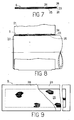
- a built-up insulating sheet S consists of a fluorine resin coated sheet 24 having a fluorine resin coating layer 24' on the right side thereof and an adhesive agent coated layer 23 on the reverse side thereof and an air-containing synthetic fabric 25 adhered to said reverse side of said fluorine resin coated sheet 24 through said adhesive agent coated layer 23.
- Said "air-containing synthetic fabric 25" in the present invention is a general term for woven fabric or knit fabric made of monofilament or multifilament of synthetic yarns such as polyamide resin and polyester resin and non-woven cloths such as span bonded cloths.
- Said air-containing synthetic fabric 25 can make the spaces formed in the meshes of fabric, knitting meshes of knit fabric and the gaps among intersecting fibers function as air-holding portions which are suitable for improving an insulating performance.
- the side of said air-containing synthetic fabrics 25 facing to said drying cylinder 22 and said adhesive agent coated layer 23 exposed from the end portion of said air-containing synthetic fabrics 25 are protected with releasing papers 26 before said built-up insulating sheet S is fixedly wound around the circumferential surface of said drying cylinder 22.
- the width of said air-containing synthetic fabrics 25 is slightly smaller than that of said fluorine resin coated sheet 24, as shown in FIG. 9, said air-containing synthetic fabrics 25 having said adhesive agent coated layer 23 exposed by 20 to 40 mm on both sides thereof either in a longitudinal direction or in a transverse direction.
- These exposed portions of said adhesive agent coated layer 23 function as adhesive surfaces for fixedly adhering said built-up insulating sheet S to the surface of said drying cylinder 22, whereby said air-conditioning synthetic fabrics 25 can be fixedly adhered to the circumferential surface of said drying cylinder 22 at the appointed positions thereof.
- an insulating layer having the same width as said air-containing synthetic fabric 25 is formed around the surface of said drying cylinder 22 at the appointed positions thereof.
- said built-up insulating sheet S is shipped by manufacturers in the form cylindrically wound but said air-containing synthetic fabrics 25 and the exposed portions of said adhesive agent coated layer 23 are protected with releasing papers 26 all over the surfaces thereof.
- said air-containing synthetic fabric 25 can be made function as insulating members by separating said releasing paper 26 and fixedly winding said built-up insulating sheet S around said drying cylinder 22 by the use of said exposed portions of said adhesive agent coated layer 23.
- sa said releasing papers 26 may be arranged so as to face only to part Q f an adhesive agent coated layer exposed outwardly of the end endge portion of an air-containing synthetic fabric.
- said cylindrically wound built-up insulating sheet S is unwound and cut in the length slightly longer than the circumference of a drying cylinder 22, that is to say longer than the circumference of a drying cylinder by 10 to 20 mm. Then the both ends of the releasing paper 26 that are to be put together later are separated from the sheet S to expose the end portions of the air-containing synthetic fabric 25, and the exposed end portions are cut away by the length of from 20 to 40 mm. That is to say, said air-containing synthetic fabric 25 is cut in the length shorter than the circumference of said drying cylinder 22 by about 10 to 20 mm.
- said releasing paper 26 is completely separated from said built-up insulating sheet S and then said built-up insulating sheet S composed of the outer layer consisting of said fluorine resin coated sheet 24 and the inner layer consisting of said air-containing synthetic fabric 25 is wound around said drying cylinder 22 at the appointed positions thereof to form strong adhesion between said built-up insulating sheet S and said drying cylinder 22 by the use of said adhesive agent coated layer 23 exposed from the end portion of said air-containing synthetic fabric 25.
- said fluorine resin coated sheet 24 is not embedded in a sinking portion formed between the end portions of said air-containing synthetic fabric 25 brought face to face with each other, as shown in FIG. 11, but forms the fixedly wound portion having an overlapping region longer than that in the preferred embodiment as shown in FIG. 4.
- the thickness of said fluorine resin coated sheet 24 is remarkably small to a degree of 0.11 mm also in this preferred embodiment, an almost flat and smooth fixedly wound portion of said built-up insulating sheet S substantially having no step along the circumferential direction is formed on the surface of said drying cylinder 22.
- synthetic monofilament yarns such as polyamide resin and polyester resin are most suitable as the constituent element of said air-containing synthetic fabric 25, in cases where woven fabrics are used as said air-containing synthetic fabric 25, it is desired to adjust the density of monofilament yarns constructing woven fabric so that the diameter of warp and weft yarns may be about 0.1 to 0.3 mm and the thickness of fabric may be about 0.2 to 0.4 mm. It is desired that the meshes of said air-containing synthetic fabric 25 functioning as air-holding portions and adjusting the moisture profile of paper web 21 being dried by said drying cylinder 22 have the porosity of 30 to 60 % based on the whole developed area of said synthetic fabric.
- said built-up insulating sheet S used in the present invention has a remarkably small built-up thickness, a step is hardly formed along the direction of width and the circumferential direction of said drying cylinder 22 at the boundary of a part of said drying cylinder 22, around which said built-up insulating sheet S is wound, and a part of said drying cylinder 22, around which said built-up insulating sheet S is not wound, when said built-up insulating sheet S is fixedly wound around said drying cylinder 22 at the appointed positions thereof.
- the present invention can provide an economically operative moisture profile controlling means for a paper web.
- the present invention can eliminate the disadvantages of the prior arts in which a heterogeneous moisture profile of a paper web is solved by the overdrying of the whole wet paper web.
- the moisture profile of a wet paper web is intended to be adjusted by the use of insulating air layers formed in the void areas among yarns. That is to say, according to the present invention, since the uniform moisture profile of a wet paper web can be always maintained, not only the quality of the final products can be improved but also the practical value of the present invention can be remarkably increased in respect of energy saving.
- a moisture profile adjusting built-up insulating sheet according to the present invention can be easily adhered to the desired portion of the surface of a drying cylinder by only separating a releasing paper therefrom, it can be correctly and speedily mounted on a drying cylinder in the facilities in which the operating conditions are not always good.
- a moisture profile adjusting built-up insulating sheet according to the present invention can speedily meet to the changes in the moisture profile of a wet paper web in the drying part of a paper making process whereby being capable of greatly contributing to the improvements of the final products in quality, a paper making process in productivity and an energy saving effect.
Landscapes
- Drying Of Solid Materials (AREA)
- Paper (AREA)
- Insulating Bodies (AREA)
Applications Claiming Priority (2)
| Application Number | Priority Date | Filing Date | Title |
|---|---|---|---|
| JP189012/83U | 1983-12-06 | ||
| JP1983189012U JPS60102299U (ja) | 1983-12-06 | 1983-12-06 | 抄紙用ドライヤ・シリンダ |
Publications (3)
| Publication Number | Publication Date |
|---|---|
| EP0163738A1 true EP0163738A1 (de) | 1985-12-11 |
| EP0163738A4 EP0163738A4 (de) | 1987-04-14 |
| EP0163738B1 EP0163738B1 (de) | 1990-05-09 |
Family
ID=16233819
Family Applications (1)
| Application Number | Title | Priority Date | Filing Date |
|---|---|---|---|
| EP84903766A Expired EP0163738B1 (de) | 1983-12-06 | 1984-10-15 | Verfahren und vorrichtung zum einstellen des wassergehaltes in papierblättern während des trocknens im papierverfahren |
Country Status (7)
| Country | Link |
|---|---|
| US (1) | US4639292A (de) |
| EP (1) | EP0163738B1 (de) |
| JP (1) | JPS60102299U (de) |
| CA (1) | CA1240141A (de) |
| DE (1) | DE3482195D1 (de) |
| FI (1) | FI83245C (de) |
| WO (1) | WO1985002634A1 (de) |
Families Citing this family (6)
| Publication number | Priority date | Publication date | Assignee | Title |
|---|---|---|---|---|
| US5571223A (en) * | 1993-06-22 | 1996-11-05 | Scapa Group Plc | Roller apparatus |
| WO1995013855A1 (en) * | 1993-11-16 | 1995-05-26 | Scapa Group Plc | Phase separation apparatus |
| US5528838A (en) * | 1994-03-25 | 1996-06-25 | The Johnson Corporation | Insulated dryer drum |
| US5667641A (en) * | 1995-10-23 | 1997-09-16 | Pulp And Paper Research Institute Of Canada | Application of thermal barrier coatings to paper machine drying cylinders to prevent paper edge overdrying |
| JP5917944B2 (ja) * | 2012-02-23 | 2016-05-18 | 日東電工株式会社 | 混紡不織布、フィルタ濾材およびフィルタユニット |
| US9481777B2 (en) | 2012-03-30 | 2016-11-01 | The Procter & Gamble Company | Method of dewatering in a continuous high internal phase emulsion foam forming process |
Family Cites Families (4)
| Publication number | Priority date | Publication date | Assignee | Title |
|---|---|---|---|---|
| US2264731A (en) * | 1938-11-10 | 1941-12-02 | Johns Manville | Ironer padding |
| US2608749A (en) * | 1948-03-20 | 1952-09-02 | Pittsburgh Waterproof Company | Ironer roll and pad with heat-reflecting sheet applied thereto |
| US2780859A (en) * | 1954-06-02 | 1957-02-12 | Kinzelman Joseph | Ironing device |
| FI53606C (fi) * | 1977-02-04 | 1978-06-12 | Eero Arthur Irpola | Foerfarande foer utjaemnande av fuktighetsprofilen vid en cylindertork samt medel foer utfoerande av foerfarandet |
-
1983
- 1983-12-06 JP JP1983189012U patent/JPS60102299U/ja active Granted
-
1984
- 1984-10-15 EP EP84903766A patent/EP0163738B1/de not_active Expired
- 1984-10-15 DE DE8484903766T patent/DE3482195D1/de not_active Expired - Lifetime
- 1984-10-15 WO PCT/JP1984/000489 patent/WO1985002634A1/ja not_active Ceased
- 1984-10-16 CA CA000465528A patent/CA1240141A/en not_active Expired
- 1984-10-19 US US06/662,481 patent/US4639292A/en not_active Expired - Fee Related
-
1985
- 1985-05-30 FI FI852176A patent/FI83245C/fi not_active IP Right Cessation
Non-Patent Citations (2)
| Title |
|---|
| No further relevant documents disclosed * |
| See also references of WO8502634A1 * |
Also Published As
| Publication number | Publication date |
|---|---|
| FI83245C (fi) | 1991-06-10 |
| FI852176L (fi) | 1985-06-07 |
| CA1240141A (en) | 1988-08-09 |
| JPS619037Y2 (de) | 1986-03-20 |
| DE3482195D1 (de) | 1990-06-13 |
| JPS60102299U (ja) | 1985-07-12 |
| FI83245B (fi) | 1991-02-28 |
| EP0163738A4 (de) | 1987-04-14 |
| US4639292A (en) | 1987-01-27 |
| FI852176A0 (fi) | 1985-05-30 |
| EP0163738B1 (de) | 1990-05-09 |
| WO1985002634A1 (fr) | 1985-06-20 |
Similar Documents
| Publication | Publication Date | Title |
|---|---|---|
| US4636426A (en) | Papermaker's fabric with yarns having multiple parallel monofilament strands | |
| CA1181622A (en) | Papermakers fabric using differential melt yarns | |
| US4776373A (en) | Fabric for the sheet forming section of a papermaking machine | |
| US7959764B2 (en) | Forming fabrics for fiber webs | |
| US4529013A (en) | Papermakers fabrics | |
| CA2087107C (en) | Loop formation in on-machine-seamed press fabrics using unique yarns | |
| JP4099398B2 (ja) | 縫合製紙布のベ−ス構造 | |
| US4632716A (en) | Woven low permeability fabric and method | |
| JPH08209580A (ja) | 乾燥布 | |
| EP0940499B1 (de) | Zusatz von strömungsverringerndem Material zur Doppelnahtverbindung von Gewebene | |
| US4476902A (en) | In-line pintle loop seam | |
| KR20000069510A (ko) | 다층/다수 심 프레스 직물의 심 완전성 개선 | |
| KR20000023827A (ko) | 건조부 직물용 봉합부 디자인 | |
| US5787602A (en) | Dryer fabric with adhesive tacky surface for web | |
| KR100327847B1 (ko) | 프레스패브릭 | |
| US4639291A (en) | Method of controlling moisture profile in paper web in paper drying process and apparatus practicing same | |
| US5562968A (en) | Textile dryer fabric | |
| CA1240141A (en) | Method of controlling moisture profile in paper web in paper drying process and apparatus practicing same | |
| US6989080B2 (en) | Nonwoven neutral line dryer fabric | |
| US5115582A (en) | Spiral fabric papermakers belt having adjustable permeability | |
| US20090047496A1 (en) | Multilayer fabric and manufacturing method thereof | |
| CA2566270A1 (en) | Improved seam for multiaxial papermaking fabrics | |
| US3581348A (en) | Seams for papermaking clothing | |
| CA1137387A (en) | Papermachine dryer fabric | |
| MXPA05013700A (en) | NONWOVEN PAPERMAKERâÇÖS FABRIC |
Legal Events
| Date | Code | Title | Description |
|---|---|---|---|
| PUAI | Public reference made under article 153(3) epc to a published international application that has entered the european phase |
Free format text: ORIGINAL CODE: 0009012 |
|
| AK | Designated contracting states |
Designated state(s): DE SE |
|
| 17P | Request for examination filed |
Effective date: 19851211 |
|
| A4 | Supplementary search report drawn up and despatched |
Effective date: 19870414 |
|
| 17Q | First examination report despatched |
Effective date: 19881013 |
|
| GRAA | (expected) grant |
Free format text: ORIGINAL CODE: 0009210 |
|
| AK | Designated contracting states |
Kind code of ref document: B1 Designated state(s): DE SE |
|
| REF | Corresponds to: |
Ref document number: 3482195 Country of ref document: DE Date of ref document: 19900613 |
|
| PLBE | No opposition filed within time limit |
Free format text: ORIGINAL CODE: 0009261 |
|
| STAA | Information on the status of an ep patent application or granted ep patent |
Free format text: STATUS: NO OPPOSITION FILED WITHIN TIME LIMIT |
|
| 26N | No opposition filed | ||
| PGFP | Annual fee paid to national office [announced via postgrant information from national office to epo] |
Ref country code: SE Payment date: 19931018 Year of fee payment: 10 |
|
| PGFP | Annual fee paid to national office [announced via postgrant information from national office to epo] |
Ref country code: DE Payment date: 19931222 Year of fee payment: 10 |
|
| PG25 | Lapsed in a contracting state [announced via postgrant information from national office to epo] |
Ref country code: SE Effective date: 19941016 |
|
| EAL | Se: european patent in force in sweden |
Ref document number: 84903766.8 |
|
| EUG | Se: european patent has lapsed |
Ref document number: 84903766.8 |
|
| PG25 | Lapsed in a contracting state [announced via postgrant information from national office to epo] |
Ref country code: DE Effective date: 19950801 |