EP0163870A2 - Dispositif pour soulever et évacuer des récipients à ordures d'un véhicule à ordures - Google Patents
Dispositif pour soulever et évacuer des récipients à ordures d'un véhicule à ordures Download PDFInfo
- Publication number
- EP0163870A2 EP0163870A2 EP85104544A EP85104544A EP0163870A2 EP 0163870 A2 EP0163870 A2 EP 0163870A2 EP 85104544 A EP85104544 A EP 85104544A EP 85104544 A EP85104544 A EP 85104544A EP 0163870 A2 EP0163870 A2 EP 0163870A2
- Authority
- EP
- European Patent Office
- Prior art keywords
- containers
- conveyor
- container
- lifting
- lowered
- Prior art date
- Legal status (The legal status is an assumption and is not a legal conclusion. Google has not performed a legal analysis and makes no representation as to the accuracy of the status listed.)
- Granted
Links
Images



Classifications
-
- B—PERFORMING OPERATIONS; TRANSPORTING
- B65—CONVEYING; PACKING; STORING; HANDLING THIN OR FILAMENTARY MATERIAL
- B65F—GATHERING OR REMOVAL OF DOMESTIC OR LIKE REFUSE
- B65F9/00—Transferring of refuse between vehicles or containers with intermediate storage or pressing
-
- B—PERFORMING OPERATIONS; TRANSPORTING
- B65—CONVEYING; PACKING; STORING; HANDLING THIN OR FILAMENTARY MATERIAL
- B65G—TRANSPORT OR STORAGE DEVICES, e.g. CONVEYORS FOR LOADING OR TIPPING, SHOP CONVEYOR SYSTEMS OR PNEUMATIC TUBE CONVEYORS
- B65G63/00—Transferring or trans-shipping at storage areas, railway yards or harbours or in opening mining cuts; Marshalling yard installations
- B65G63/002—Transferring or trans-shipping at storage areas, railway yards or harbours or in opening mining cuts; Marshalling yard installations for articles
- B65G63/004—Transferring or trans-shipping at storage areas, railway yards or harbours or in opening mining cuts; Marshalling yard installations for articles for containers
Definitions
- the invention relates to a device for lifting containers forming refillable containers from refuse collection vehicles and for their removal.
- garbage collection vehicles are known which, as part of an interchangeable container garbage collection system, collect garbage and transport the container filled with garbage into one serve as a central container transhipment point at which the filled containers are exchanged for empty ones and from which the filled containers are transported to landfills by special vehicles.
- This swap body garbage collection system ensures economical garbage disposal because the garbage collection vehicles specially designed for collecting garbage can be used predominantly for collecting work and only need to travel as short as possible to the central container handling point, and because special transport vehicles are used to transport the swap bodies to more distant landfills that can accommodate several containers.
- the containers are provided for their lifting off the chassis of the refuse collection vehicles in the area of their corners with supports that can be extended against the ground or with other lifting and supporting devices, so that they are subsequently supported Container that drive this transport vehicle and the container can be placed on it and locked with it.
- the performance and economy of the swap body waste collection system is also largely determined by the speed at which the containers can be exchanged and removed.
- the object of the invention is therefore to provide a conveniently manageable and largely automatable device of the type specified at the outset, with which the containers can be lifted off the garbage collection vehicles and transported away or made available for transport.
- a container-conveying conveyor is provided, the receiving end of which is arranged in the region of the height of the transport platform of the refuse collection vehicle and is provided with tine-shaped arms which can be moved in under the unlocked containers and which can be raised and lowered and extended beyond the receiving end and retractable in or behind it.
- the tine-shaped arms which are designed similarly to the tine-shaped forks of a forklift, first perform a feed movement under the unlocked container and then a lifting, retracting and lowering movement on the conveyor.
- the refuse collection vehicle only needs to be driven into the appropriate position in front of the receiving end of the conveyor, so that after preferably automatically unlocking the container, it is lifted by the prong-shaped arms and placed on the conveyor.
- the acceptance process takes place in a very short time, so that the refuse collection vehicle is ready for use again after picking up an empty container.
- the lifted containers are transported transversely on the conveyor, whereby after the pick-up station has been released, the next container can be lifted, set down and re-conveyed.
- the conveying device expediently consists of a roller conveyor which is inclined starting from the receiving end and which is provided with devices for braking the containers placed thereon.
- the containers are conveyed on the inclined roller conveyor by their gravity, taking them up to theirs. Decelerate or collide so that they can be provided in close succession for the purpose of being transported away.
- the braking devices expediently consist of lateral supports provided with brake pads, which extend over the conveying level can be raised and lowered below this.
- the supports can be connected to the base frame of the frame carrying the roller track via parallel links and can be raised and lowered by a pressure-medium piston-cylinder unit, the ends of which are connected in an articulated manner to the base frame and the supports or parallel links.
- the lifting and lowering of the brake beams can be automatically controlled in such a way that the containers taken over from the receiving station are conveyed on the roller conveyor in a gently sliding manner without being subjected to major shock loads.
- the containers are taken over by the transport vehicles transporting them to landfills.
- the end of the conveyor line is expediently also provided with fork-shaped tines which can be raised and lowered, retracted and retracted, for lifting the containers from the transfer end and for transferring them to a transport vehicle or the like.
- the discharge end can be provided with a pushing device for pushing the containers onto or from the transfer device.
- the device for lifting the emptied containers from the transport vehicles and for transporting and transferring them to the refuse collection vehicles is designed accordingly.
- two transport, acceptance and transfer devices are arranged parallel to each other at the central container handling point, so that the refuse collection vehicles hand in their containers at the receiving station of the first conveyor and after an onward journey a few meters at the end of the following conveyor already pick up an empty container again.
- the transport vehicles release and pick up empty or filled containers in a corresponding manner at the opposite ends of the conveyor devices.
- Corresponding conveying devices can be provided in the area of the landfills, which serve to unload and load the transport vehicles and which provide the containers for the purpose of tipping and pick up the emptied containers again and prepare them for removal.
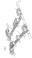
- the central container transfer point shown in FIG. 1 consists of the conveyor 1, which takes over the filled containers 3 delivered by the garbage collection vehicles 2, conveys them to the end of delivery and transfers them to the container transport vehicles 4, which can load three containers.
- the fundamentally appropriately constructed conveying device 5 is arranged with an opposite conveying direction, which takes over the empty containers transported by the container transport vehicle 4 in the manner shown and places them on the refuse collection vehicles 2.
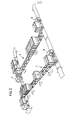
- a container handling point is shown, which is located in the area of a landfill.
- the container transport vehicles 4 deliver the containers 3, which are taken over by the receiving end of the conveyor 6 and provided at the discharge end in such a way that they can be taken over by the transport vehicles 8, which only serve to transport the containers to the landfill and to tip them .
- the correspondingly constructed conveyor device 7 with the opposite conveying direction is arranged parallel to the conveyor device 6. From the transport vehicles 8, the tilted containers are fed to the receiving end of the conveyor 7 and removed therefrom. The transversely conveyed empty containers 3 are taken over by the transport vehicles 4 at the discharge end of the conveying device 7 and fed back to the central container handling point according to FIG. 1.
- the filled containers 3 could also be removed from the conveying device 6 and tilted by other conveying devices and fed back to the feed conveyor 7.
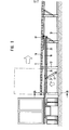
- This consists of a roller 10 carrying frame 10, which is supported on a base frame 13 via support 12.
- the rollers 11 are rotatably supported on both sides of the frame 10 in tabs 13, 14 welded to the frame. They have lateral frustoconical guide edges 15.
- the Containcr 3 are provided on their undersides with parallel runners 16 with which they are supported on the rollers 11 and which are guided between the edges 15.
- a guide frame 18 is pivotally mounted on the frame 10 about the axis 17, in its lateral U-shaped guides a carriage 20 carrying the tines 19 is guided longitudinally.
- the piston rod 21 of a pressure medium piston cylinder unit is articulated thereon, the cylinder 22 of which is articulated to the base frame 13.
- the piston rod 24 of a pressure medium piston cylinder unit is articulated to the slide 20, the cylinder 25 of which is articulated to the rear central region 18.
- a Brernsbalken 28 provided with a: brake lining 27, which is articulated to the base frame 13 of the roller conveyor via parallel links 39.
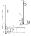
- the container 3 is provided in the area of the firing beam 28 in the manner shown in FIG. 5 with a brake rail 30.
- the piston rod 31 of a pressure medium piston cylinder unit, the cylinder 32 of which is articulated to the base frame 13, is articulated to the brake beam 28.
- the handlebars 29 supporting the brake bar 28 assume an inclined position, so that by extending the piston rod 31 the brake bar 28 can be raised above the plane of the upper surface lines of the rollers 11 and can brake the containers 3 rolling on the inclined roller track.
- sliders 40 are provided, the angled ends of which engage behind bolts 41 of the container 3 and push them onto the container transport vehicles.
- the sliders 40 consist of angle levers and are mounted on a carriage 42, which can be moved back and forth in guides by a pressure medium piston cylinder unit 43.
- the consisting of angle levers Sliders are held in their push position by tension springs 43 against a stop of the carriage 42. If the sliders 42 are retracted, they can be pivoted clockwise against the force of the spring 43 in the manner shown in FIGS. 7 and 8 and pulled away under the containers.
- extendable zinc-shaped arms can be provided which can expediently be raised and lowered.
Landscapes
- Engineering & Computer Science (AREA)
- Mechanical Engineering (AREA)
- Refuse Collection And Transfer (AREA)
- Intermediate Stations On Conveyors (AREA)
- Refuse-Collection Vehicles (AREA)
- Loading Or Unloading Of Vehicles (AREA)
Priority Applications (1)
| Application Number | Priority Date | Filing Date | Title |
|---|---|---|---|
| AT85104544T ATE47119T1 (de) | 1984-05-29 | 1985-04-15 | Vorrichtung zum abheben und abtransportieren von muellcontainern von muellsammelfahrzeugen. |
Applications Claiming Priority (2)
| Application Number | Priority Date | Filing Date | Title |
|---|---|---|---|
| DE19843420059 DE3420059A1 (de) | 1984-05-29 | 1984-05-29 | Vorrichtung zum abheben und abtransportieren von muellcontainern von muellsammelfahrzeugen |
| DE3420059 | 1984-05-29 |
Publications (3)
| Publication Number | Publication Date |
|---|---|
| EP0163870A2 true EP0163870A2 (fr) | 1985-12-11 |
| EP0163870A3 EP0163870A3 (en) | 1987-02-04 |
| EP0163870B1 EP0163870B1 (fr) | 1989-10-11 |
Family
ID=6237151
Family Applications (1)
| Application Number | Title | Priority Date | Filing Date |
|---|---|---|---|
| EP85104544A Expired EP0163870B1 (fr) | 1984-05-29 | 1985-04-15 | Dispositif pour soulever et évacuer des récipients à ordures d'un véhicule à ordures |
Country Status (4)
| Country | Link |
|---|---|
| US (1) | US4728241A (fr) |
| EP (1) | EP0163870B1 (fr) |
| AT (1) | ATE47119T1 (fr) |
| DE (2) | DE3420059A1 (fr) |
Cited By (3)
| Publication number | Priority date | Publication date | Assignee | Title |
|---|---|---|---|---|
| EP2765096A1 (fr) * | 2013-02-12 | 2014-08-13 | Veolia Proprete | Ensemble de collecte et d'évacuation de déchets ménagers |
| EP2765097A1 (fr) * | 2013-02-12 | 2014-08-13 | Veolia Proprete | Ensemble de collecte et d'évacuation de déchets ménagers |
| CN109353801A (zh) * | 2018-11-15 | 2019-02-19 | 苏州耐德新明和工程技术有限公司 | 一种平面换箱系统 |
Families Citing this family (18)
| Publication number | Priority date | Publication date | Assignee | Title |
|---|---|---|---|---|
| US4907933A (en) * | 1988-08-15 | 1990-03-13 | Fmc Corporation | Pallet unloader |
| US5662450A (en) * | 1989-01-12 | 1997-09-02 | Transwest Management | Sectional van trailer having detachable and interchangeable compartments for transporting both household belongings and commercial freight |
| US5326213A (en) * | 1989-01-12 | 1994-07-05 | Roberts Hardy G | Section van trailer having detachable and interchangeable compartments for transporting both household belongings and commercial freight |
| CA2061379C (fr) * | 1991-08-22 | 1995-11-14 | William T. Stewart | Convoyeur a palette reglable |
| US5403142A (en) * | 1991-08-22 | 1995-04-04 | Stewart-Glapat Corporation | Pallet handling adjustable conveyor |
| SE9402504D0 (sv) * | 1994-07-18 | 1994-07-18 | Sten Loevgren | Förfarande och anordning för hantering av laster |
| US5562390A (en) * | 1995-01-24 | 1996-10-08 | Mcneilus Truck And Manufacturing, Inc. | Detachable truck body and handling mechanism |
| US6733027B2 (en) | 2002-06-19 | 2004-05-11 | Delaware Capital Formation, Inc. | Detachable truck body/semi trailer |
| US20060072993A1 (en) * | 2004-10-04 | 2006-04-06 | Delaware Capital Formation, Inc. | Refuse collection system and method |
| CA2525165C (fr) * | 2005-11-02 | 2010-08-03 | Les Aciers Solider (1985) Inc. | Systeme de transfert de charge pour camions a plate-forme |
| US11162834B2 (en) * | 2012-11-30 | 2021-11-02 | Bace, Llc | Weight-measurement retrofitting for waste compactors |
| CN107487580B (zh) * | 2016-09-30 | 2020-06-02 | 宝沃汽车(中国)有限公司 | 一种物料存储系统 |
| CN106494809A (zh) * | 2016-12-30 | 2017-03-15 | 安徽海螺川崎工程有限公司 | 垃圾接收卸料系统 |
| WO2019123337A1 (fr) * | 2017-12-19 | 2019-06-27 | Albuquerque E Povoas Antonio Jose | Équipement et procédé pour transfert autonome de charge entre récepteur de ripage et structure d'appui |
| CN114524285B (zh) * | 2020-11-23 | 2025-02-28 | 张志文 | 医疗废弃物自动装卸系统及装卸方法 |
| CN113911767B (zh) * | 2021-09-26 | 2023-10-27 | 浪潮通用软件有限公司 | 一种基于界面操作的点包机装车方法及设备 |
| US12545000B1 (en) | 2022-05-02 | 2026-02-10 | Marathon Equipment Company | Bale weighing system |
| CN115303826B (zh) * | 2022-10-11 | 2023-03-10 | 太原市富利恒自动化科技有限公司 | 一种货车自动装车设备 |
Family Cites Families (23)
| Publication number | Priority date | Publication date | Assignee | Title |
|---|---|---|---|---|
| US31060A (en) * | 1861-01-01 | John h | ||
| US561631A (en) * | 1896-06-09 | Lumber-loading apparatus | ||
| US2107569A (en) * | 1935-12-31 | 1938-02-08 | Cons Iron Steel Mfg Company | Loading device |
| US2627960A (en) * | 1947-07-18 | 1953-02-10 | Journal Company | Loading conveyer |
| US3017157A (en) * | 1960-02-11 | 1962-01-16 | Specialties Dev Corp | Lanyard actuated valve |
| FR1332474A (fr) * | 1962-08-28 | 1963-07-12 | Atomic Energy Authority Uk | Transporteurs à rouleaux |
| US3374878A (en) * | 1966-07-25 | 1968-03-26 | Andrew T. Kornylak | Roller conveyor system |
| DE1755118A1 (de) * | 1968-03-30 | 1971-12-30 | Josef Froetschl | Lade- und Entladegeraet,vorzugsweise fuer Lastkraftwagen |
| US3640410A (en) * | 1969-06-30 | 1972-02-08 | Kysor Industrial Corp | Waste-materials-handling system |
| US3721354A (en) * | 1970-07-27 | 1973-03-20 | Rohr Industries Inc | Materials handling system |
| US3853230A (en) * | 1971-07-29 | 1974-12-10 | G Schultz | Loader/unloader conveyor system |
| US3826347A (en) * | 1972-05-03 | 1974-07-30 | Kornylac Co | Conveyor apparatus |
| FI56808C (fi) * | 1973-02-07 | 1980-04-10 | Sten Esse Torgild Idoffsson | Anordning foer oeverfoering av avfall fraon haemtningsfordon till ett med en behaollare foersett transportfordon |
| DD102362A1 (fr) * | 1973-03-08 | 1973-12-12 | ||
| US3913758A (en) * | 1973-06-15 | 1975-10-21 | Green Thumb Corp | Horticulture apparatus |
| US3952887A (en) * | 1974-04-16 | 1976-04-27 | Lutz David E | Vehicle loading and unloading apparatus |
| FR2275389A1 (fr) * | 1974-06-20 | 1976-01-16 | Lucas Raymond | Dispositif de transfert d'une charge d'un convoyeur a un autre destine a vehiculer des palettes et autres charges |
| NO139381C (no) * | 1975-03-24 | 1979-02-28 | Linjegods As | Anordning for overfoering av lastbaerere fra en jernbanevogn til en lastebil og omvendt |
| US4136763A (en) * | 1976-12-06 | 1979-01-30 | Pryor Roy R | Sawmill stop assembly module |
| USRE31060E (en) | 1977-12-29 | 1982-10-19 | Automatic Truckloading Systems, Inc. | Article handling apparatus |
| US4277217A (en) * | 1979-06-07 | 1981-07-07 | A-T-O Inc. | Load transfer apparatus |
| US4459732A (en) * | 1981-09-21 | 1984-07-17 | Driggers Robert H | Stove roller |
| US4383598A (en) * | 1981-12-28 | 1983-05-17 | Newman Frank E | Conveyor control apparatus |
-
1984
- 1984-05-29 DE DE19843420059 patent/DE3420059A1/de not_active Withdrawn
-
1985
- 1985-04-15 AT AT85104544T patent/ATE47119T1/de not_active IP Right Cessation
- 1985-04-15 EP EP85104544A patent/EP0163870B1/fr not_active Expired
- 1985-04-15 DE DE8585104544T patent/DE3573590D1/de not_active Expired
- 1985-05-14 US US06/733,864 patent/US4728241A/en not_active Expired - Lifetime
Cited By (5)
| Publication number | Priority date | Publication date | Assignee | Title |
|---|---|---|---|---|
| EP2765096A1 (fr) * | 2013-02-12 | 2014-08-13 | Veolia Proprete | Ensemble de collecte et d'évacuation de déchets ménagers |
| EP2765097A1 (fr) * | 2013-02-12 | 2014-08-13 | Veolia Proprete | Ensemble de collecte et d'évacuation de déchets ménagers |
| FR3001960A1 (fr) * | 2013-02-12 | 2014-08-15 | Veolia Proprete | Ensemble de collecte et d'evacuation de dechets menagers |
| FR3001959A1 (fr) * | 2013-02-12 | 2014-08-15 | Veolia Proprete | Ensemble de collecte et d'evacuation de dechets menagers |
| CN109353801A (zh) * | 2018-11-15 | 2019-02-19 | 苏州耐德新明和工程技术有限公司 | 一种平面换箱系统 |
Also Published As
| Publication number | Publication date |
|---|---|
| US4728241A (en) | 1988-03-01 |
| ATE47119T1 (de) | 1989-10-15 |
| EP0163870A3 (en) | 1987-02-04 |
| DE3420059A1 (de) | 1985-12-12 |
| EP0163870B1 (fr) | 1989-10-11 |
| DE3573590D1 (en) | 1989-11-16 |
Similar Documents
| Publication | Publication Date | Title |
|---|---|---|
| EP0163870B1 (fr) | Dispositif pour soulever et évacuer des récipients à ordures d'un véhicule à ordures | |
| DE2545051A1 (de) | Muell-sammel- und transportfahrzeug | |
| DE3804090C2 (fr) | ||
| AT409617B (de) | Speicherwagen zur speicherung von schüttgut | |
| AT394530B (de) | Schuettgutverladewagen | |
| DE102007063286A1 (de) | Verfahren und Vorrichtung zum Verpacken von Getränke-Großgebinden | |
| AT400729B (de) | Maschine zum austauschen der schwellen eines gleises | |
| DE4020221A1 (de) | Fahrzeug zum einsammeln von abfaellen | |
| DE3228015C2 (fr) | ||
| DE1756380A1 (de) | Verfahren und Vorrichtung zur UEbergabe von Guetern zwischen in Bewegung befindlichenFoerderern | |
| EP2100834B9 (fr) | Dispositif de manipulation destiné au transport de récipients remplis et/ou devant être remplis d'articles | |
| DE3005529C2 (de) | Palettiervorrichtung | |
| DE69007216T2 (de) | Eisenbahnwagen für den Transport von Schutt. | |
| DE2004549A1 (de) | Verladevorrichtung für Säcke | |
| EP0102972B1 (fr) | Dispositif de preparation des commandes de longues marchandises posees sur palettes, dans un entrepot comprenant des rayonnages separes par des allees | |
| DE1531953A1 (de) | Vorrichtung zum Entladen von Stueckgut von einer Palette und zum UEberfuehren desselben zu einem Foerderer | |
| EP1254987B1 (fr) | Méthode pour renouveler le ballast et machine | |
| AT515413B1 (de) | Verfahren zur Sanierung einer Schotterbettung eines Gleises | |
| DE3602076C2 (fr) | ||
| DE8220884U1 (de) | Vorrichtung zum stapeln von stueck- oder sackgut auf paletten | |
| EP0460570B1 (fr) | Installation pour la pose en continu des traverses d'une voie ferrée | |
| DE2454876A1 (de) | Anlage zur aufbereitung von muell, insbesondere haushaltsmuell | |
| EP1314666B1 (fr) | Procédé et dispositif de manipulation des bagages dans les aéroports | |
| DE19913985A1 (de) | Umschlageinrichtung zum Entleeren und Weiterfördern von mit Schüttgut gefüllten Containern | |
| DE19634038A1 (de) | Verfahren und Vorrichtung zum Recyceln von Hausmüll |
Legal Events
| Date | Code | Title | Description |
|---|---|---|---|
| PUAI | Public reference made under article 153(3) epc to a published international application that has entered the european phase |
Free format text: ORIGINAL CODE: 0009012 |
|
| AK | Designated contracting states |
Designated state(s): AT BE CH DE FR GB IT LI LU NL SE |
|
| PUAL | Search report despatched |
Free format text: ORIGINAL CODE: 0009013 |
|
| AK | Designated contracting states |
Kind code of ref document: A3 Designated state(s): AT BE CH DE FR GB IT LI LU NL SE |
|
| 17P | Request for examination filed |
Effective date: 19870704 |
|
| 17Q | First examination report despatched |
Effective date: 19880509 |
|
| RAP1 | Party data changed (applicant data changed or rights of an application transferred) |
Owner name: EDELHOFF M.S.T.S. GMBH |
|
| GRAA | (expected) grant |
Free format text: ORIGINAL CODE: 0009210 |
|
| AK | Designated contracting states |
Kind code of ref document: B1 Designated state(s): AT BE CH DE FR GB IT LI LU NL SE |
|
| REF | Corresponds to: |
Ref document number: 47119 Country of ref document: AT Date of ref document: 19891015 Kind code of ref document: T |
|
| REF | Corresponds to: |
Ref document number: 3573590 Country of ref document: DE Date of ref document: 19891116 |
|
| ET | Fr: translation filed | ||
| ITF | It: translation for a ep patent filed | ||
| GBT | Gb: translation of ep patent filed (gb section 77(6)(a)/1977) | ||
| PLBE | No opposition filed within time limit |
Free format text: ORIGINAL CODE: 0009261 |
|
| STAA | Information on the status of an ep patent application or granted ep patent |
Free format text: STATUS: NO OPPOSITION FILED WITHIN TIME LIMIT |
|
| 26N | No opposition filed | ||
| ITTA | It: last paid annual fee | ||
| PGFP | Annual fee paid to national office [announced via postgrant information from national office to epo] |
Ref country code: LU Payment date: 19930414 Year of fee payment: 9 |
|
| PGFP | Annual fee paid to national office [announced via postgrant information from national office to epo] |
Ref country code: SE Payment date: 19930415 Year of fee payment: 9 Ref country code: AT Payment date: 19930415 Year of fee payment: 9 |
|
| PGFP | Annual fee paid to national office [announced via postgrant information from national office to epo] |
Ref country code: CH Payment date: 19930625 Year of fee payment: 9 |
|
| EPTA | Lu: last paid annual fee | ||
| PG25 | Lapsed in a contracting state [announced via postgrant information from national office to epo] |
Ref country code: LU Free format text: LAPSE BECAUSE OF NON-PAYMENT OF DUE FEES Effective date: 19940415 Ref country code: AT Effective date: 19940415 |
|
| PG25 | Lapsed in a contracting state [announced via postgrant information from national office to epo] |
Ref country code: SE Effective date: 19940416 |
|
| PG25 | Lapsed in a contracting state [announced via postgrant information from national office to epo] |
Ref country code: LI Effective date: 19940430 Ref country code: CH Effective date: 19940430 |
|
| REG | Reference to a national code |
Ref country code: CH Ref legal event code: PL |
|
| EUG | Se: european patent has lapsed |
Ref document number: 85104544.3 Effective date: 19941110 |
|
| PGFP | Annual fee paid to national office [announced via postgrant information from national office to epo] |
Ref country code: GB Payment date: 19950320 Year of fee payment: 11 |
|
| PGFP | Annual fee paid to national office [announced via postgrant information from national office to epo] |
Ref country code: FR Payment date: 19950404 Year of fee payment: 11 |
|
| PGFP | Annual fee paid to national office [announced via postgrant information from national office to epo] |
Ref country code: BE Payment date: 19950407 Year of fee payment: 11 |
|
| PGFP | Annual fee paid to national office [announced via postgrant information from national office to epo] |
Ref country code: DE Payment date: 19950427 Year of fee payment: 11 |
|
| PGFP | Annual fee paid to national office [announced via postgrant information from national office to epo] |
Ref country code: NL Payment date: 19950430 Year of fee payment: 11 |
|
| PG25 | Lapsed in a contracting state [announced via postgrant information from national office to epo] |
Ref country code: GB Effective date: 19960415 |
|
| PG25 | Lapsed in a contracting state [announced via postgrant information from national office to epo] |
Ref country code: BE Effective date: 19960430 |
|
| BERE | Be: lapsed |
Owner name: EDELHOFF M.S.T.S. G.M.B.H. Effective date: 19960430 |
|
| PG25 | Lapsed in a contracting state [announced via postgrant information from national office to epo] |
Ref country code: NL Effective date: 19961101 |
|
| GBPC | Gb: european patent ceased through non-payment of renewal fee |
Effective date: 19960415 |
|
| PG25 | Lapsed in a contracting state [announced via postgrant information from national office to epo] |
Ref country code: FR Effective date: 19961227 |
|
| PG25 | Lapsed in a contracting state [announced via postgrant information from national office to epo] |
Ref country code: DE Effective date: 19970101 |
|
| NLV4 | Nl: lapsed or anulled due to non-payment of the annual fee |
Effective date: 19961101 |
|
| REG | Reference to a national code |
Ref country code: FR Ref legal event code: ST |
|
| REG | Reference to a national code |
Ref country code: FR Ref legal event code: TP |
|
| REG | Reference to a national code |
Ref country code: FR Ref legal event code: TP Free format text: CORRECTION |