EP0163982A2 - Dispositif de commande du gonflage successif des chambres individuelles d'un garrot pneumatique - Google Patents
Dispositif de commande du gonflage successif des chambres individuelles d'un garrot pneumatique Download PDFInfo
- Publication number
- EP0163982A2 EP0163982A2 EP85105783A EP85105783A EP0163982A2 EP 0163982 A2 EP0163982 A2 EP 0163982A2 EP 85105783 A EP85105783 A EP 85105783A EP 85105783 A EP85105783 A EP 85105783A EP 0163982 A2 EP0163982 A2 EP 0163982A2
- Authority
- EP
- European Patent Office
- Prior art keywords
- control body
- outlet
- membrane
- control
- connection
- Prior art date
- Legal status (The legal status is an assumption and is not a legal conclusion. Google has not performed a legal analysis and makes no representation as to the accuracy of the status listed.)
- Granted
Links
Images


Classifications
-
- A—HUMAN NECESSITIES
- A61—MEDICAL OR VETERINARY SCIENCE; HYGIENE
- A61H—PHYSICAL THERAPY APPARATUS, e.g. DEVICES FOR LOCATING OR STIMULATING REFLEX POINTS IN THE BODY; ARTIFICIAL RESPIRATION; MASSAGE; BATHING DEVICES FOR SPECIAL THERAPEUTIC OR HYGIENIC PURPOSES OR SPECIFIC PARTS OF THE BODY
- A61H9/00—Pneumatic or hydraulic massage
- A61H9/005—Pneumatic massage
- A61H9/0078—Pneumatic massage with intermittent or alternately inflated bladders or cuffs
-
- A—HUMAN NECESSITIES
- A61—MEDICAL OR VETERINARY SCIENCE; HYGIENE
- A61H—PHYSICAL THERAPY APPARATUS, e.g. DEVICES FOR LOCATING OR STIMULATING REFLEX POINTS IN THE BODY; ARTIFICIAL RESPIRATION; MASSAGE; BATHING DEVICES FOR SPECIAL THERAPEUTIC OR HYGIENIC PURPOSES OR SPECIFIC PARTS OF THE BODY
- A61H2201/00—Characteristics of apparatus not provided for in the preceding codes
- A61H2201/50—Control means thereof
- A61H2201/5053—Control means thereof mechanically controlled
Definitions
- the invention relates to a control device for successively filling individual chambers with a gaseous medium.
- individual chambers can be, for example, flexible, hose-like chambers combined into a sleeve.
- the cuffs formed in this way are used, for example, for decongesting extremities, for example arms or legs. For this it is necessary that all chambers are filled with the gaseous pressure medium one after the other. The next chamber may only be filled when the previous chamber has reached the desired pressure.
- Known control devices which should enable such successive filling of the individual chambers, are very complex and expensive and do not always work satisfactorily.
- the invention is therefore based on the object of proposing a control device of the type described at the outset which is extremely simple in construction and yet works absolutely reliably.
- a control device of the type described in the introduction by a control body with an inlet connection and a desired number of outlet connections for the medium, a channel having an outlet on an outer surface of the control body being provided at least for each outlet connection in the control body, and wherein each Exit is covered by a flexible membrane covering all outlets.
- compressed air is used to fill the individual chambers of a cuff given the inlet connection, the compressed air enters the associated channel and exits and thereby raises the supple membrane, so must work against the back pressure exerted by the membrane.
- the compressed air then travels under the membrane until it finds a first alternative and this is an outlet which opens into an outlet connection with an assigned channel, which in turn is connected to the first chamber of a cuff to be filled. At this point, the pressure immediately drops and flows into the first chamber of the cuff.
- the chamber is filled until a pressure rise in the supply line and thus also in the associated outlet connection arises through the chamber filling, which continues again via the assigned outlet below the flexible cover membrane and now raises it against the back pressure exerted by the cover membrane, so that the compressed air can move again under the membrane thus raised until it finds another outlet without counter pressure, through which it can flow out again via the assigned outlet connection, this further assigned outlet connection then being connected to the next chamber of the sleeve.
- each outlet is separated from each other outlet by an intermediate web, the flexible covering membrane being placed over the intermediate webs. In this way, the accuracy of the pressure adjustment can be refined.
- the last outlet connection seen from the inlet connection leads into the free atmosphere via the assigned outlet with a channel, while all other outlet connections are each provided for a connection to an assigned individual chamber to be filled.
- control body with the cover membrane for the outlets is surrounded by a hollow body, the hollow body to the membrane and the membrane to the control body being sealed on the one hand before the first outlet and on the other hand behind the last outlet of the control body, and wherein the hollow body in the area between the front and rear Sealing has an inlet opening for a pressure medium.
- This structure represents a particularly simple and functionally reliable means for arbitrarily and extremely finely regulating the pressure with which the individual chambers of a cuff are inflated.
- the structure described makes it possible to apply a control pressure to the membrane from the outside via the inlet opening mentioned, so that the membrane can be more or less pressed with its inner surface against the corresponding counter surface of the control body, so that. a correspondingly changed pressure of the pressure medium for the individual chambers to be inflated is required to lift off the membrane, which in turn achieves a corresponding pressure regulation of the chamber pressure of the individual chambers of the cuffs.
- control body is designed as a cylindrical body. This enables a particularly simple manufacture of the control body.
- the cover membrane is designed as a piece of hose of approximately the same length as the control body. This is a very simple possibility of producing this membrane, which can be pulled over the control body in the manner of a valve rubber, in particular if the control body is designed as a cylindrical body.
- a supplementary embodiment of the invention provides that the hollow body surrounding the control body is designed as a tubular piece open at both ends, approximately of the length of the control body. This also greatly simplifies the production of the hollow body, and it is particularly advantageous to use the hollow body designed as a tubular piece to be used together with a control body designed as a cylindrical body, in which case the cover membrane should then advantageously also be designed as a piece of hose.
- the cover membrane should then advantageously also be designed as a piece of hose.
- a further embodiment of the invention provides that the control body has on its cylindrical outer surface annular ducts separated by annular intermediate webs, at least one outlet opening into each annular duct and only one annular duct being provided for the inlet connection and for each outlet connection.
- an O-ring is provided as the front and rear seal, which is arranged between the hollow body and the membrane.
- a channel covered by the membrane is provided for each O-ring on the control body. This makes it easy to axially fix the O-ring and at the same time to seal the membrane very securely against the control body via the channel edges.
- a further embodiment of the invention provides that the last outlet connection is provided on one end face of the control body, while the remaining outlet connections and the inlet connection are provided on the opposite end face of the control body. In this way, a clearly manageable division of the different connections is achieved and the space available is also improved. At the same time, incorrect connection is definitely prevented, which could impair the functionality of the device.
- control body has at one end a connecting disk, on the peripheral surface of which at least some of the connections are provided.
- a connecting disk on the peripheral surface of which at least some of the connections are provided.
- a supplementary embodiment provides that the connecting disk is circular cylindrical. This is the simplest manufacturing option, which also allows simple, radial attachment of the connectors.
- the connecting disk is provided on an end face of the cylindrical control body.
- the improved space for the connectors becomes clear because otherwise the connection options would be limited to the surface of the end face of the cylindrical control body.
- additional space for the connecting pieces is easily obtained.
- connecting disk and the cylindrical control body are formed in one piece. As a result, sealing elements between the connecting disk and the control body can be dispensed with.
- the connecting disk has a larger diameter than the control body and is arranged outside the hollow body surrounding the control body. In this way, an impairment of the hollow body can be avoided and additional space is nevertheless gained for the connecting pieces.
- the size of the control body can be adapted to the desired space for connectors.
- the control body be designed as a prismatoid.
- a prismatoid can create space for desired functions at desired locations. For example, this makes it possible to lay the necessary connections in a row to be arranged when, for example, the control body is designed as a cuboid body. The necessary connections can then, for example, be arranged in a row next to one another on the long sides or end faces of this body, as a result of which the functional overview is improved in certain applications.
- this design allows the training of the entire facility as so-called. Plug-in module, so that collaboration with other devices can be achieved in the simplest way and it is also possible without any problems to replace the control device quickly and without complications.
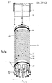
- FIG. 1 shows a control device, from which it is initially to be assumed that the control body used there should be the control body 14, that is to say a cylindrical control body in the illustration according to FIG. 3 or FIG. 4.
- the entire length of the cylindrical control body 14 is covered with a tubular rubber skin as membrane 29 (see Figure 1a).
- the control body 14 coated with the membrane 29 in this way is inserted with radial play into a tubular hollow body 17 which is approximately the same length as the control body 14.
- This hollow body 17 has a radially directed inlet opening 37 in the vicinity of the rear end, which is equipped with a hose connector 41.
- Hose connection piece 41 is connected to a pressure source 42 for a flow medium via a control pressure line 12 and pressure regulating devices (not shown).
- the radial space between the outer surface of the membrane 29 and the inner surface of the hollow body 17 is sealed in the region of the two ends of the hollow body 17 with an O-ring 25 and 26, respectively.
- the control body 14 has a number of annular channels 33 on its surface, which are delimited by annular intermediate webs 32. In each of these annular channels 33 there is an outlet opening 34 and 35, each subsequent outlet opening 34 preferably being arranged somewhat offset in the circumferential direction with respect to the previous outlet opening 34.
- an inlet port 1 and the outlet ports 2 to 10 are arranged on the front side 22 of the control body 14 .
- the connections 1 to 10 mentioned are each connected to the outlets 34 and 35 via longitudinal bores in the control body 14.
- inlet connection 1 is connected to outlet 34.
- the inlet connection 2 is connected to the lowest outlet 35 in FIG. 1, etc.
- This outlet port 11 can lead directly into the free atmosphere 38, or serve as a connector to other devices, in the embodiment with a silencer 43.
- the O-ring 25 before the first outlet that is to say before the outlet 34
- the 0-ring 26 is arranged behind the last outlet, that is to say behind the outlets 36, which lead into the outlet connection 11.
- the outlet connections 2 to 10 are each connected to an assigned individual chamber 39 via suitable lines, all of the chambers 39 being combined to form a sleeve 40.
- These individual chambers can be ring-shaped, for example Form tubes so that this cuff 40 can be placed over an arm or a leg, for example.
- the inlet port 1 is connected to a pressure source 44 which is suitable for filling the chambers 39 and thus the cuff 40 with pressure medium in the desired manner.
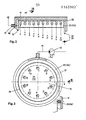
- the control body 15 used there essentially corresponds in its construction to the control body 14. However, it does not immediately have the desired connections on its end face 19, like the control body 14, but rather a connecting disk 16 is provided there, which is either sealed off from the control body 15 or is formed in one piece with it.
- the connecting disk 16 is preferably larger in diameter than the control body 15, so that on the one hand a larger circumferential surface 20 is available and on the other hand the hollow body 17 can be pushed from behind against the connecting disk 16 which now acts as a stop. This makes assembly easier.
- control body 13 is designed as a plate-shaped body with a rectangular cross-section.
- the plate-shaped body 13 is also encompassed by the membrane 29.
- membrane 29 may well be designed as a piece of tubing, since the flexible membrane 29 adapts easily to the body shape of the control body 13.
- straight channels can be incorporated on one side of the control body 13, similar to the channels 33 according to FIG. 1.
- the illustration according to FIG. 1 can also be seen as a view in the direction of the arrow A according to FIG. 2, so that the figure then 1 shows the course and the arrangement of the channels 33 as they are to be used in FIG. 2. Complete channels are then not required.
- the outlets 34 and 35 assigned to the connections 1 to 10 can again be seen in an arrangement which is shown in FIG. Associated with these exits are the connections 1 to 10 on the end face 23 of the control body 13 in a row-shaped arrangement, as shown in FIG.
- Each of these connections 1 to 10 is connected to the associated outlet 34 or 35 via a longitudinal bore.
- the last channel with the outlets 36, which are assigned to the outlet connection 11, is no longer shown in FIG.
- the arrangement can also be seen in FIG. 1 if it is assumed that FIG. 1 is a view in the direction of arrow A in FIG. 2.
- the changed body shape of the control body 13 also makes it sensible to design the hollow body 18 in accordance with the body shape of the control body 13.
- the inner cross section of the hollow body 18 is again somewhat larger than the outer dimensions of the control body 13, so that the Intermediate space again in the front and rear area in the position already described in FIG. 1 can be provided with a seal, whereby in this case the seal can also be a 0-ring 27 or 28 which is sufficiently elastic to conform to the shape of the Adjust control body 13 and the hollow body 18.
- the hollow body 18 is shown broken off, it expediently includes the control body 13 completely, but leaves the end cross-sections open outside of the seal.
- the hollow body 18 is again equipped with an inlet opening 37 in the arrangement shown in FIG.
- this inlet opening 37 again having a hose connector 41 and being connected via a control pressure line 12 to the pressure source 42 already mentioned.
- This flat design according to FIG. 2 enables it to be designed as a plug-in module and also makes such a control unit stackable in a simple manner.
- the embodiment according to FIG. 2 also makes it possible to combine such control units into batteries in a particularly advantageous manner and to couple them together if required.
- the outlet connection 11 provided on the end face 24 is connected to the inlet connection 1 of the next control unit via an intermediate line.
- a pressure source 44 suitable for this purpose must first be connected to the inlet connection 1, for example of the control body 14.
- the pressure medium supplied by the pressure source 44 then exits at the outlet 34 and enters the associated ring channel and expands the membrane 29 as soon as the ring channel is filled. Due to the expansion of the membrane 29, the pressure medium can now exceed the first annular intermediate web 32 and enter the next annular channel and there enter the first outlet 35 and fill the first individual chamber 39 via the assigned outlet connection 2.
- control line 12 and the inlet opening 37 in the hollow body 17 or 18 can act on the membrane 29 from the outside with control pressure.
- a greater internal pressure is required to lift the membrane off, so that the pressure medium supplied by the pressure source 44 reaches the next channel in each case.
- the desired internal pressure of the individual chambers 39 can thus be easily adjusted.
- the setting is extremely precise.
- connection of a single control unit is not sufficient, it is easily possible to combine several control units into one functional unit. It is only necessary to connect the outlet port 11 of a previous device to the inlet port 1 of a subsequent device. The following device can also be acted upon with the same control pressure. In the subsequent device, the same process then takes place as already described, so that further individual chambers or further individual chambers of a next cuff can then be subsequently filled with the subsequent device.
Landscapes
- Health & Medical Sciences (AREA)
- Public Health (AREA)
- Physical Education & Sports Medicine (AREA)
- Rehabilitation Therapy (AREA)
- Life Sciences & Earth Sciences (AREA)
- Animal Behavior & Ethology (AREA)
- Pain & Pain Management (AREA)
- General Health & Medical Sciences (AREA)
- Veterinary Medicine (AREA)
- Epidemiology (AREA)
- Vehicle Body Suspensions (AREA)
- Hydraulic Clutches, Magnetic Clutches, Fluid Clutches, And Fluid Joints (AREA)
- Exhaust-Gas Circulating Devices (AREA)
- Measuring Pulse, Heart Rate, Blood Pressure Or Blood Flow (AREA)
- External Artificial Organs (AREA)
- Quick-Acting Or Multi-Walled Pipe Joints (AREA)
- Invalid Beds And Related Equipment (AREA)
Priority Applications (1)
| Application Number | Priority Date | Filing Date | Title |
|---|---|---|---|
| AT85105783T ATE47305T1 (de) | 1984-05-17 | 1985-05-10 | Steuereinrichtung zum sukzessiven auffuellen von einzelkammern, z.b. einer druckmanschette. |
Applications Claiming Priority (2)
| Application Number | Priority Date | Filing Date | Title |
|---|---|---|---|
| DE19848415045U DE8415045U1 (de) | 1984-05-17 | 1984-05-17 | Steuereinrichtung |
| DE8415045U | 1984-05-17 |
Publications (3)
| Publication Number | Publication Date |
|---|---|
| EP0163982A2 true EP0163982A2 (fr) | 1985-12-11 |
| EP0163982A3 EP0163982A3 (en) | 1986-12-17 |
| EP0163982B1 EP0163982B1 (fr) | 1989-10-18 |
Family
ID=6766990
Family Applications (2)
| Application Number | Title | Priority Date | Filing Date |
|---|---|---|---|
| EP85105783A Expired EP0163982B1 (fr) | 1984-05-17 | 1985-05-10 | Dispositif de commande du gonflage successif des chambres individuelles d'un garrot pneumatique |
| EP85105784A Expired EP0163183B1 (fr) | 1984-05-17 | 1985-05-10 | Dispositif de commande du gonflage successif des chambres individuelles d'un garrot pneumatique |
Family Applications After (1)
| Application Number | Title | Priority Date | Filing Date |
|---|---|---|---|
| EP85105784A Expired EP0163183B1 (fr) | 1984-05-17 | 1985-05-10 | Dispositif de commande du gonflage successif des chambres individuelles d'un garrot pneumatique |
Country Status (3)
| Country | Link |
|---|---|
| EP (2) | EP0163982B1 (fr) |
| AT (2) | ATE47305T1 (fr) |
| DE (3) | DE8415045U1 (fr) |
Cited By (2)
| Publication number | Priority date | Publication date | Assignee | Title |
|---|---|---|---|---|
| DE4017182A1 (de) * | 1989-06-01 | 1990-12-06 | Boesl Medizintechnik Fa | Ventil |
| EP0459081B1 (fr) * | 1990-05-29 | 1994-12-21 | Bösl Medizintechnik Gmbh | Vanne |
Families Citing this family (3)
| Publication number | Priority date | Publication date | Assignee | Title |
|---|---|---|---|---|
| DE3676120D1 (de) * | 1985-05-23 | 1991-01-24 | Hans Boesl | Behandlungseinrichtung mit manschette und steuereinrichtung. |
| DE19846922C2 (de) * | 1998-10-12 | 2003-12-11 | Manuel Fernandez | Behandlungsvorrichtung |
| DE102014001678B3 (de) * | 2014-02-07 | 2014-07-31 | Faurecia Autositze Gmbh | Massageeinrichtung für einen Fahrzeugsitz sowie Verfahren zu deren Ansteuerung |
Family Cites Families (4)
| Publication number | Priority date | Publication date | Assignee | Title |
|---|---|---|---|---|
| CH157774A (de) * | 1931-05-15 | 1932-10-15 | Hoflinger Bruno | Vorrichtung zum Ansammeln des Blutes an einer bestimmten Stelle des menschlichen Körpers. |
| US3862629A (en) * | 1973-05-02 | 1975-01-28 | Nicholas R Rotta | Fluid pressure controlled means for producing peristaltic operation of series-connected inflatable chambers in therapeutic devices, pumps and the like |
| DE3009408A1 (de) * | 1980-03-12 | 1981-09-17 | Leonhard Heinrich 7821 Feldberg Eck | Vorrichtung zur oedembehandlung |
| DE8422043U1 (de) * | 1984-05-17 | 1985-02-28 | Bösl, Hans, 5100 Aachen | Steuereinrichtung |
-
1984
- 1984-05-17 DE DE19848415045U patent/DE8415045U1/de not_active Expired
-
1985
- 1985-05-10 AT AT85105783T patent/ATE47305T1/de not_active IP Right Cessation
- 1985-05-10 AT AT85105784T patent/ATE47304T1/de not_active IP Right Cessation
- 1985-05-10 EP EP85105783A patent/EP0163982B1/fr not_active Expired
- 1985-05-10 DE DE8585105784T patent/DE3573719D1/de not_active Expired
- 1985-05-10 EP EP85105784A patent/EP0163183B1/fr not_active Expired
- 1985-05-10 DE DE8585105783T patent/DE3573720D1/de not_active Expired
Cited By (2)
| Publication number | Priority date | Publication date | Assignee | Title |
|---|---|---|---|---|
| DE4017182A1 (de) * | 1989-06-01 | 1990-12-06 | Boesl Medizintechnik Fa | Ventil |
| EP0459081B1 (fr) * | 1990-05-29 | 1994-12-21 | Bösl Medizintechnik Gmbh | Vanne |
Also Published As
| Publication number | Publication date |
|---|---|
| DE3573719D1 (en) | 1989-11-23 |
| EP0163982A3 (en) | 1986-12-17 |
| DE8415045U1 (de) | 1984-12-06 |
| EP0163183A3 (en) | 1986-12-17 |
| EP0163982B1 (fr) | 1989-10-18 |
| EP0163183A2 (fr) | 1985-12-04 |
| ATE47304T1 (de) | 1989-11-15 |
| EP0163183B1 (fr) | 1989-10-18 |
| DE3573720D1 (en) | 1989-11-23 |
| ATE47305T1 (de) | 1989-11-15 |
Similar Documents
| Publication | Publication Date | Title |
|---|---|---|
| EP2047110B1 (fr) | Dispositif technique fluidique | |
| EP3515767B1 (fr) | Soupape de régulation de pression d'un système de traitement d'air dans un véhicule utilitaire | |
| EP0163982B1 (fr) | Dispositif de commande du gonflage successif des chambres individuelles d'un garrot pneumatique | |
| DE2829216C2 (de) | Heizmittelverteiler | |
| DE102020117374B3 (de) | Pneumatisch betätigtes Schaltventil, Ventilanordnung und Beatmungssystem | |
| DE2229536A1 (de) | Bremskraftverstärker in Tandemanordnung | |
| DE9314120U1 (de) | Druckbegrenzungsventil mit integriertem Rückschlagventil | |
| DE3628543A1 (de) | Anschlussverbindungsstueck | |
| DE3120535A1 (de) | Vorrichtung zu steuern des antriebs und der wasserzufuhr fuer ein dental-luftturbinenhandstuecks | |
| DE102014225279A1 (de) | Anschlussvorrichtung für eine Fluidleitung | |
| EP0745796A1 (fr) | Robinet modulaire | |
| DE102014009178B4 (de) | Rückschlagventil und damit ausgestattete Vakuum-Arbeitsvorrichtung | |
| DE8422043U1 (de) | Steuereinrichtung | |
| EP0679828B1 (fr) | Connecteur pour conduite pneumatique ou hydraulique et son utilisation dans le domaine dentaire | |
| DE4017182C2 (fr) | ||
| DE2622703C3 (de) | Pneumatischer Druckregler | |
| EP0474017B1 (fr) | Vérin pneumatique, en particulier pour véhicules | |
| DE2108769A1 (de) | Vorrichtung zur Herstellung pneumatischer logischer Schaltungen | |
| DE102015209940B4 (de) | Kanalmodulanordnung | |
| EP2194308B1 (fr) | Pièce de couplage pour pièces de raccordement de tuyau annelé | |
| EP0020872A1 (fr) | Installation de chauffage à eau chaude ou de préparation d'eau chaude avec un éjecteur réglable et éjecteur pour cette installation | |
| EP1517072B1 (fr) | Vanne | |
| DE3401591C2 (fr) | ||
| DE1947017C3 (de) | Wechselventil mit einem zur Umschaltung dienenden Steuerventil | |
| DE2816502A1 (de) | Schalteinheit, insbesondere fuer fliessmitteldruckbetaetigte systeme |
Legal Events
| Date | Code | Title | Description |
|---|---|---|---|
| PUAI | Public reference made under article 153(3) epc to a published international application that has entered the european phase |
Free format text: ORIGINAL CODE: 0009012 |
|
| AK | Designated contracting states |
Designated state(s): AT BE CH DE FR GB IT LI LU NL SE |
|
| PUAL | Search report despatched |
Free format text: ORIGINAL CODE: 0009013 |
|
| AK | Designated contracting states |
Kind code of ref document: A3 Designated state(s): AT BE CH DE FR GB IT LI LU NL SE |
|
| 17P | Request for examination filed |
Effective date: 19870323 |
|
| 17Q | First examination report despatched |
Effective date: 19880608 |
|
| GRAA | (expected) grant |
Free format text: ORIGINAL CODE: 0009210 |
|
| AK | Designated contracting states |
Kind code of ref document: B1 Designated state(s): AT BE CH DE FR GB IT LI LU NL SE |
|
| REF | Corresponds to: |
Ref document number: 47305 Country of ref document: AT Date of ref document: 19891115 Kind code of ref document: T |
|
| ITF | It: translation for a ep patent filed | ||
| REF | Corresponds to: |
Ref document number: 3573720 Country of ref document: DE Date of ref document: 19891123 |
|
| GBT | Gb: translation of ep patent filed (gb section 77(6)(a)/1977) | ||
| ET | Fr: translation filed | ||
| PLBE | No opposition filed within time limit |
Free format text: ORIGINAL CODE: 0009261 |
|
| STAA | Information on the status of an ep patent application or granted ep patent |
Free format text: STATUS: NO OPPOSITION FILED WITHIN TIME LIMIT |
|
| 26N | No opposition filed | ||
| GBPC | Gb: european patent ceased through non-payment of renewal fee | ||
| PGFP | Annual fee paid to national office [announced via postgrant information from national office to epo] |
Ref country code: LU Payment date: 19910327 Year of fee payment: 7 |
|
| PGFP | Annual fee paid to national office [announced via postgrant information from national office to epo] |
Ref country code: SE Payment date: 19910409 Year of fee payment: 7 |
|
| PGFP | Annual fee paid to national office [announced via postgrant information from national office to epo] |
Ref country code: FR Payment date: 19910424 Year of fee payment: 7 |
|
| PGFP | Annual fee paid to national office [announced via postgrant information from national office to epo] |
Ref country code: GB Payment date: 19910509 Year of fee payment: 7 |
|
| PGFP | Annual fee paid to national office [announced via postgrant information from national office to epo] |
Ref country code: AT Payment date: 19910515 Year of fee payment: 7 |
|
| REG | Reference to a national code |
Ref country code: GB Ref legal event code: 728C |
|
| ITTA | It: last paid annual fee | ||
| PGFP | Annual fee paid to national office [announced via postgrant information from national office to epo] |
Ref country code: NL Payment date: 19910531 Year of fee payment: 7 Ref country code: BE Payment date: 19910531 Year of fee payment: 7 |
|
| PGFP | Annual fee paid to national office [announced via postgrant information from national office to epo] |
Ref country code: DE Payment date: 19910618 Year of fee payment: 7 Ref country code: CH Payment date: 19910618 Year of fee payment: 7 |
|
| EPTA | Lu: last paid annual fee | ||
| REG | Reference to a national code |
Ref country code: GB Ref legal event code: 728A |
|
| PG25 | Lapsed in a contracting state [announced via postgrant information from national office to epo] |
Ref country code: LU Free format text: LAPSE BECAUSE OF NON-PAYMENT OF DUE FEES Effective date: 19920510 Ref country code: GB Effective date: 19920510 Ref country code: AT Effective date: 19920510 |
|
| PG25 | Lapsed in a contracting state [announced via postgrant information from national office to epo] |
Ref country code: SE Effective date: 19920511 |
|
| PG25 | Lapsed in a contracting state [announced via postgrant information from national office to epo] |
Ref country code: LI Effective date: 19920531 Ref country code: CH Effective date: 19920531 Ref country code: BE Effective date: 19920531 |
|
| BERE | Be: lapsed |
Owner name: BOSL HANS Effective date: 19920531 |
|
| PG25 | Lapsed in a contracting state [announced via postgrant information from national office to epo] |
Ref country code: NL Effective date: 19921201 |
|
| GBPC | Gb: european patent ceased through non-payment of renewal fee |
Effective date: 19920510 |
|
| NLV4 | Nl: lapsed or anulled due to non-payment of the annual fee | ||
| PG25 | Lapsed in a contracting state [announced via postgrant information from national office to epo] |
Ref country code: FR Effective date: 19930129 |
|
| REG | Reference to a national code |
Ref country code: CH Ref legal event code: PL |
|
| PG25 | Lapsed in a contracting state [announced via postgrant information from national office to epo] |
Ref country code: DE Effective date: 19930202 |
|
| REG | Reference to a national code |
Ref country code: FR Ref legal event code: ST |
|
| EUG | Se: european patent has lapsed |
Ref document number: 85105783.6 Effective date: 19921204 |