EP0164171A1 - Absperreinrichtung für eine Leitung - Google Patents
Absperreinrichtung für eine Leitung Download PDFInfo
- Publication number
- EP0164171A1 EP0164171A1 EP85200838A EP85200838A EP0164171A1 EP 0164171 A1 EP0164171 A1 EP 0164171A1 EP 85200838 A EP85200838 A EP 85200838A EP 85200838 A EP85200838 A EP 85200838A EP 0164171 A1 EP0164171 A1 EP 0164171A1
- Authority
- EP
- European Patent Office
- Prior art keywords
- valve
- pipe
- shutoff device
- elements
- intermediate plate
- Prior art date
- Legal status (The legal status is an assumption and is not a legal conclusion. Google has not performed a legal analysis and makes no representation as to the accuracy of the status listed.)
- Withdrawn
Links
Images


Classifications
-
- F—MECHANICAL ENGINEERING; LIGHTING; HEATING; WEAPONS; BLASTING
- F16—ENGINEERING ELEMENTS AND UNITS; GENERAL MEASURES FOR PRODUCING AND MAINTAINING EFFECTIVE FUNCTIONING OF MACHINES OR INSTALLATIONS; THERMAL INSULATION IN GENERAL
- F16L—PIPES; JOINTS OR FITTINGS FOR PIPES; SUPPORTS FOR PIPES, CABLES OR PROTECTIVE TUBING; MEANS FOR THERMAL INSULATION IN GENERAL
- F16L41/00—Branching pipes; Joining pipes to walls
- F16L41/08—Joining pipes to walls or pipes, the joined pipe axis being perpendicular to the plane of a wall or to the axis of another pipe
- F16L41/16—Joining pipes to walls or pipes, the joined pipe axis being perpendicular to the plane of a wall or to the axis of another pipe the branch pipe comprising fluid cut-off means
-
- F—MECHANICAL ENGINEERING; LIGHTING; HEATING; WEAPONS; BLASTING
- F16—ENGINEERING ELEMENTS AND UNITS; GENERAL MEASURES FOR PRODUCING AND MAINTAINING EFFECTIVE FUNCTIONING OF MACHINES OR INSTALLATIONS; THERMAL INSULATION IN GENERAL
- F16K—VALVES; TAPS; COCKS; ACTUATING-FLOATS; DEVICES FOR VENTING OR AERATING
- F16K27/00—Construction of housing; Use of materials therefor
-
- F—MECHANICAL ENGINEERING; LIGHTING; HEATING; WEAPONS; BLASTING
- F16—ENGINEERING ELEMENTS AND UNITS; GENERAL MEASURES FOR PRODUCING AND MAINTAINING EFFECTIVE FUNCTIONING OF MACHINES OR INSTALLATIONS; THERMAL INSULATION IN GENERAL
- F16K—VALVES; TAPS; COCKS; ACTUATING-FLOATS; DEVICES FOR VENTING OR AERATING
- F16K31/00—Actuating devices; Operating means; Releasing devices
- F16K31/02—Actuating devices; Operating means; Releasing devices electric; magnetic
- F16K31/06—Actuating devices; Operating means; Releasing devices electric; magnetic using a magnet, e.g. diaphragm valves, cutting off by means of a liquid
Definitions
- the invention relates to a shutoff device for at least one pipe, where the latter debouches into a pipe flange or pipe plate.
- shutoff device by means of which such vessels in which the undesirable reaction products are produced - and if necessary also all other vessels connected by means of the pipe system - can quickly be shut off, and where it must be seen clearly which vessel(s) is (are) shut off. With the aid of, for example, suitable detectors, it can then be established if necessary which vessel was shut off first. In that case, it is often only necessary to take out of service this one vessel in which the fault has occurred. Not until this has been done may other shutoff devices which are closed be opened again, preferably deliberately by hand.
- the invention now produces a shutoff device which meets the above-mentioned requirements, and which is characterised by:
- the present invention deliberately selects for the shutoff device a place where the pipe(s) debouch(es) by means of the pipe flange or pipe plate in a vessel or housing, since this provides the greatest possible protection of the connected pipes and other devices. Moreover, in consideration of the available space, such a shutoff device can be fitted simply here, including also the elements by which the position of the valve of the shutoff device can be observed from the outside, and by means of which this valve can be opened again by hand.
- the combination with the flange or intermediate plate also has the advantage that, if necessary, after the shutting off of the pipe(s) a vessel or housing can easily be taken out of service or changed, without pipes which may be welded having to be detached.
- the complete shutoff unit for example, the intermediate plate with the parts accommodated in it, is also easy to replace.
- valve can be closed only by spring force.
- electromagnetic elements need be excited only briefly, for example using a capacitor pulse. After closure of the valve, this can be observed clearly from the outside, while opening has to be carried out deliberately.
- the valve is fitted on one end of an arm, which is supported in an intermediate point so as to rotate or swivel, in such a way that through the rotation or swivelling of said arm the valve can be shifted to and from the entrance to the debouchment or the debouchment itself.
- the other end of said swivelling arm can then be conveyed, for example by means of bellow sealed in a gastight fashicn, outside the pipe flange, the pipe plate or the intermediate plate and can be locked here by means of a step against spring force, in such a way that the valve is held in the open position.
- the said stop is operated by the electromagnetic elements.
- the spring force can be taken from a spring which, for example, works in conjunction with the end of the swivelling arm on which the valve is fitted.
- the valve can shut off the debouchment of the pipe itself, or also an opening in the intermediate plate which gives access to the debouchment.
- the free end of the swivelling arm can also work in conjunction with a bar which is fitted transversely to it and is conveyed gastight to the outside, and with the free end of which the said stop can again work together.
- the gastight passage can again comprise cylindrical bellows, which are preferably fitted on a concave connecting piece, whose cavity is in line with the recess of the swivelling arm, said connecting piece being again fitted so as to be gastight on the pipe flange or on the intermediate plate.
- the shutoff device is characterised in that the valve is carried by one end of a first swivelling arm, whose other end is rigidly connected to a rotating coupling shaft transverse to this first swivelling arm, so that through the rotation of said coupling shaft, the first swivelling arm can execute a swivel movement for the desired movement of the valve to the closed position or the open position, said rotating coupling shaft being taken via sealing elements outside the pipe flange, pipe plate or intermediate plate, and in its external end being rigidly connected to a second swivelling arm whose free end works in conjunction with a movable step and by means of said stop can be held sgainst spring force in a position in which the valve is open, said stop being capable of being pulled by the above-mentioned electromagnetic elements outside the holding position, in which case the spring elements can move the above-mentioned assembly of swivelling arms, valve and rotating coupling shaft to a position in which the entrance to the
- the spring elements can be constituted by a compression or draw spring, one end of which is connected to the free end of the second swivelling arm, while the other end is connected to a fixed point of the pipe flange, pipe plate or intermediate plate.
- a compression spring for example a leaf spring, can also work in conjunction with the end of the first swivelling arm on which the valve is fitted. In this case, this compression spring can be accommodated in the area of the pipe flange, pipe plate or intermediate plate in which the valve is located.
- the valve can shut off the debouchment of the pipe itself directly in the pipe flange or pipe plate, but it can also shut off, for example, an opening provided opposite this pipe debouchment in the pipe plate. During removal of the vessel, this can then remain closed if the connection between the pipe flange or pipe plate and the intermediate plate is detached, but not the connection between the intermediate plate and the vessel.
- the mechanical shifting elements are formed by a bar which is movable in its longitudinal direction and which essentially extends into the plane of the pipe flange or intermediate plate, and on one end of which the valve is fitted, while the other end is conveyed in a gastight fashion outside the pipe flange or intermediate plate and works here in conjunction with the above-mentioned stcp.
- the valve works together with a valve seat which is practically transverse to the plane of the pipe flange or intermediate plate and surrounds a passage between a space which is connected to the pipe and a space which debouches outside the pipe flange or intermediate plate.
- the bar can be surrounded by a compression or draw spring which pretensions the valve in the closing direction.
- the sealing elements can also be formed here by cylindrical, bellows sealed in a gastight fashion,through which part of the bar which is movable in its longitudinal direction extends, and whose free end is conveyed through a plate which closes off one end of the bellows, while the other end of the bellows is connected with the pipe flange or intermediate plate or herewith via a hollow connecting piece.
- the electromagnetic elements are here preferably formed by a coil which extends concentrically round the bar, and an annular armature which also extends concentrically round the bar, and which is moved through the magnetic field produced on excitation of the coil.
- the armature works in conjunction with a stop which holds the bar under spring tension- in a position in which the valve is open, and which is pulled out of this position on movement of the armature, so that the valve can be closed.
- Fig. 1 shows a top view of the pipe flange 1, which is fastened with bolts 2 to a vessel which is not shown. Connected with this pipe flange are, for example, four pipes 3 standing close together. Each entrance to a pipe debouchment is provided with its own shutoff device according to the invention. Opposite each pipe debouchment there is here a valve 4. See also Fig. 2. This valve 4 is rotatably connected by means of a shaft 5 to one end of a first swivelling arm 6, whose other end is rigidly connected to a coupling rod or shaft 7 standing transversely to this swivelling arm 6.
- valve 4 The valve 4, the shaft 5, the first swivelling arm 6, the coupling shaft 7 and the sealing elements 8 therefor are illustrated by dotted lines in Fig. 1, because they are located under the top face of the pipe flange 1. A view of parts of them is shown in Fig. 2.
- the shutoff device is accommodated in an intermediate plate 18.
- This intermediate plate 18 is provided with the necessary recesses 9 for the purpose, i.e. a large recess containing all debouchments, or a separate recess opposite each pipe.
- Located in the recess 9 are the valve 4 and the swivelling arm 6, and there is, of course, sufficient space to move the valve 4 from the closed position to the open position shown in Fig. 2.
- the recess 9 is provided on the bottom side with openings' 25.
- the valve 4 can also shut off this opening 25 instead of the entrance to the pipe 3. In that case the valve has to be turned 180 degrees and also be shifted accordingly by the shifting elements, for the purpose of shutting off this opening 25.
- the valve 4 is also provided with a sealing ring which is accommodated in a ring groove of the valve.
- the intermediate plate 18 is clamped by means of bolts 2 between the pipe flange 1 and a housing or vessel not shown.
- Figs. 1 and 3 show the magnetic elements and the stop operated by these magnetic elements. These magnetic elements are carried by a yoke 11, which is fitted here on the top face of the pipe flange 1, for example using bolts 2, by means of which this pipe flange is also fixed on a housing or vessel.
- Fig. 1 also shows the second swivelling arm 12, which is fitted outside the flange 1 on the end of the coupling shaft 7.
- This swivelling arm 12 extends in roughly the same direction as the first swivelling arm 6, which is inside the intermediate plate 18.
- the second swivelling arm 12 has on its free end a retaining element 13. It can also be seen from Fig. 3 that this second swivelling arm 12 is drawn upwards by a spring 14, while the first swivelling arm will also undergo the same displacement and the valve 4 with the sealing ring 10 is pressed against the debouchment of the pipe 3.
- This draw spring 14 is attached at its other end to a fixed point on the yoke 11.
- the electromagnetic elements comprise a coil 15 and an armature 16.
- the armature 16 is provided at 17 with a projecting step.
- Fig. 3 the armature 16 is shown in the position in which it is drawn through excitation of the magnetic coil towards the yoke of said coil. In this position the valve 4 is closed by the spring 14. From this position of the second swivelling arm 12 and of the armature 16 it is clear from the outside that the valve 4 is in the closed position.
- Fig. 3 shows with dotted lines the positions of the armature 16 with step 17 and the second swivelling arm 12 when the valve is open and the retaining element 13 is resting behind the stop 17 and is drawn against it by the spring 14. For the unlocking of the step and closing of the valve the magnetic elements need only be fed a short electrical pulse.
- the second swivelling arm When the valve has to be opened again, the second swivelling arm must be deliberately pressed down and the armature 16 must then be pushed to the left until the step 17 can be pushed behind the projecting retaining element 13 of the second swivelling arm.
- the cam 17 can also be moved behind the retaining element 13 by means of spring elements acting on the armature 16. In that case the swivelling arm 12 need only be pressed down for reopening of the valve 4.
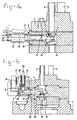
- Fig. 4 shows a second embodiment of a shutoff device according to the invention.
- valve 4 is fitted on one end of an elongated straight swivelling arm 26, which is rotatably mounted at 19. Under the end of this swivelling arm 26, where the valve 4 is fitted, there is a curved leaf spring which can press the valve and the end of the swivelling arm 26 connected to it into the position in which the debouchment of-the pipe is closed.
- the swivelling arm 26 extends to the left beyond the intermediate plate 18 and is mounted in a separate concave connecting piece or cylinder 21 which can be pushed into a suitable bore in the intermediate plate 18. Thereafter this connecting piece is welded with a flange on the intermediate plate 18, so that a gastight seal is obtained.
- this connecting piece 21 which is beyond the intermediate plate 18 are flexible cylindrical bellows 22.
- a sealing piece or plate 23 which is provided ith a retaining element 24.
- the swivelling arm 26 extends into a bore in this sealing plate 23 and is also welded in a gastight fashion onto it.
- the swivelling arm 18 can be rotated or swivelled about the shaft 19.
- the retaining element 24 can again work in conjunction with a stop 17 (only schematically illustrated) of the electromagetnic elements shown, for example, in Fig. 3, but in this case they have to be fixed in a different manner to the pipe flange 1 or intermediate plate 18.
- the swivelling arm 26 can also swivel in rocking fashion about, for example, an edge of a cam which forms part of the cylindrical part of the connecting piece 21 and rests in a groove of the swivelling arm 26, as illustrated by the dotted lines 27 on the top side of the swivelling arm 26.
- Fig. 5 shows a third embodiment of the shutoff device according to the invention, which shows some similarity with the shutoff device according to Fig. 4, but in this case the valve 4 is mounted on the bottom side of the swivelling arm 26, and the opening 25 is shut off.
- the swivelling arm 26 is connected on the left to a bar 29 which is essentially transverse to said swivelling arm 26, and on the top side of which a flange 30 is mounted.
- a compression or draw spring 14 which rests on the one side against the flange 30 and on the other against a top end of a concave extension piece 28 whose righthand cylindrical narrowed part 31 is pushed into the recess in the intermediate plate 18 in which the swivelling arm 26 and the valve are accommodated.
- the bar 29 is conducted by means of sealing elements 8 through a bore which debouches transversely in a cavity 31 in the connecting piece 28.
- This connecting piece 28 is, of course, welded in gastight fashion to the intermediate plate 18.
- Fig. 6 shows a shutoff device similar to that of Fig. 5, but here the sealing elements 8 are replaced by cylindrical bellows 22, which are welded in a gastight fashion on the bottom side to the hollow extension piece 28, which is accommodated, again by means of a cylindrical part 31, in the intermediate plate 18 and is welded in a gastight fashion to it.
- the bar 29 is welded in a gastight fashion on a flange 30, which is in turn connected in a gastight fashion to the top side of the bellows 22.
- these bellows 22 can take over the function of the spring 14.
- the external pressure must, of course, be greater than the pressure inside the bellows and inside the recess in the intermediate plate 18 and in the pipes.
- the flange 30 is pressed downwards, and the valve 4 is pressed against the debouchment of the pipe 3 as soon as the stop 17 is drawn away.
- Shown at 32 is an arm which is connected to an armature of the electromagnetic elements.
- This arm has at 17 the earlier- mentioned stop.
- the flange can be drawn upwards by means of the extension piece on the top of the bar 29.
- the arm 32 can be pressed to the left, following which the stop 17 will again hold the edge of the flange 30 until the arm 32 is attracted again by the electromagnetic elements.
- a compression or draw spring can, of course, be used for closing the valve 4. It can then work, for example, on the top side of the flange 30.
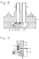
- Fig. 7 shows yet another embodiment of the emergency shutoff device according to the invention.
- valve is mounted on one end of a push bar 32, which is conveyed through a bore in an extension piece 28, which is in turn pushed into a recess in the intermediate plate 18 and welded to it.
- This intermediate plate 18 is provided with a valve seat 33, which encloses a passage to a space 34 which is connected with the pipe 3 of the pipe flange, and a space 35 which leads downwards and can be connected here to a passage to-a vessel or housing to be connected.
- the valve 4 is in this case therefore placed transversely to said direction.
- the push bar 32 runs to the left and emerges on the outside at 36.
- the push bar 32 is coaxially surrounded by a compression spring 14, a coil 15 of the electromagnetic elements and an armature 16.
- This armature is mounted on a cylindrical part 37 which fits in sliding fashion round the push bar 32.
- a compression spring 14 whose other end presses against a ring 38, which is attached on the push bar 32.
- a stop element 39 Working together with the armature 16 is a stop element 39, whose left end forms the stop 17 for holding the valve 4 in the open position.
- the part of the shutoff device with the coil, spring, armature and push bar 32 projects from the intermediate plate 18.
- these parts can project radially from a, for example, round. intermediate plate 18.
- Figs. 8, 9, 10 and 11 show variants of the working together of the valve 4 and a push bar 32, which can be used, for example in the embodiment according to Fig. 7.
- Fig. 8 the-end of the push bar 32 is provided with a bevelled part which works together with a slanting part of a stop which is fixed to the bottom side of the valve 4.
- a valve seat (not shown) round the debouchment of a pipe (not shown either) for a compression spring which moves the valve 4 downwards again when the bar 32 is drawn to the left.
- Fig. 9 shows a variant of the embodiment according to Fig. 8.
- a bar attached to the bottom side of the valve 4 is provided with a transverse pin which extends through a groove 41 in the push bar 32.
- the end of the push bar 32 can be, for example, forked, so that a tooth of the fork is on either side of the bar fixed on the bottom side of the valve 4.
- Each tooth is then provided with a recess 41.
- valve will be moved up and down depending on whether the push bar 32 is moved to the right or to the left.
- Figs. 10 and 11 again shown another variant for operating the valve 4 if a radially movable push bar 32 is used.
- a leaf sgring 42 is clamped between the right end of the push bar 32 and a bar part 43 which is mounted in a bore in the wall of the recess for the valve 4 opposite the end of the bar 32.
- This spring is curved upwards, and in the middle of this compression sgring 42 the valve 4 is mounted.
Landscapes
- Engineering & Computer Science (AREA)
- General Engineering & Computer Science (AREA)
- Mechanical Engineering (AREA)
- Mechanically-Actuated Valves (AREA)
- Magnetically Actuated Valves (AREA)
Applications Claiming Priority (2)
| Application Number | Priority Date | Filing Date | Title |
|---|---|---|---|
| NL8401658A NL8401658A (nl) | 1984-05-24 | 1984-05-24 | Afsluitinrichting voor een pijp. |
| NL8401658 | 1984-05-24 |
Publications (1)
| Publication Number | Publication Date |
|---|---|
| EP0164171A1 true EP0164171A1 (de) | 1985-12-11 |
Family
ID=19843997
Family Applications (1)
| Application Number | Title | Priority Date | Filing Date |
|---|---|---|---|
| EP85200838A Withdrawn EP0164171A1 (de) | 1984-05-24 | 1985-05-23 | Absperreinrichtung für eine Leitung |
Country Status (2)
| Country | Link |
|---|---|
| EP (1) | EP0164171A1 (de) |
| NL (1) | NL8401658A (de) |
Cited By (3)
| Publication number | Priority date | Publication date | Assignee | Title |
|---|---|---|---|---|
| EP0684415A1 (de) * | 1994-05-24 | 1995-11-29 | Hubert Bösch | Ventilmechanik für ein Vakuumventil |
| CN108130691A (zh) * | 2018-03-12 | 2018-06-08 | 安徽工程大学 | 一种使用拉伸弹簧的洗衣机防鼠装置 |
| US12072050B2 (en) | 2019-10-08 | 2024-08-27 | Ipex Technologies Inc. | Push-fit pipe fitting |
Citations (4)
| Publication number | Priority date | Publication date | Assignee | Title |
|---|---|---|---|---|
| US2875617A (en) * | 1957-07-30 | 1959-03-03 | Frank W Murphy | Magnetically controlled fuel valve |
| US3134271A (en) * | 1962-01-29 | 1964-05-26 | Gen Controls Co | Structure utilizing electric release |
| FR1421500A (fr) * | 1964-11-03 | 1965-12-17 | Eclipse Fuel Engineering Compa | Vanne d'arrêt automatique |
| US3817283A (en) * | 1971-04-07 | 1974-06-18 | J Hewson | Differential pressure transducer process mounting support |
-
1984
- 1984-05-24 NL NL8401658A patent/NL8401658A/nl unknown
-
1985
- 1985-05-23 EP EP85200838A patent/EP0164171A1/de not_active Withdrawn
Patent Citations (4)
| Publication number | Priority date | Publication date | Assignee | Title |
|---|---|---|---|---|
| US2875617A (en) * | 1957-07-30 | 1959-03-03 | Frank W Murphy | Magnetically controlled fuel valve |
| US3134271A (en) * | 1962-01-29 | 1964-05-26 | Gen Controls Co | Structure utilizing electric release |
| FR1421500A (fr) * | 1964-11-03 | 1965-12-17 | Eclipse Fuel Engineering Compa | Vanne d'arrêt automatique |
| US3817283A (en) * | 1971-04-07 | 1974-06-18 | J Hewson | Differential pressure transducer process mounting support |
Cited By (5)
| Publication number | Priority date | Publication date | Assignee | Title |
|---|---|---|---|---|
| EP0684415A1 (de) * | 1994-05-24 | 1995-11-29 | Hubert Bösch | Ventilmechanik für ein Vakuumventil |
| US5755426A (en) * | 1994-05-24 | 1998-05-26 | Boesch; Hubert | Valve mechanism for a vacuum valve |
| CN108130691A (zh) * | 2018-03-12 | 2018-06-08 | 安徽工程大学 | 一种使用拉伸弹簧的洗衣机防鼠装置 |
| CN108130691B (zh) * | 2018-03-12 | 2023-05-05 | 安徽工程大学 | 一种使用拉伸弹簧的洗衣机防鼠装置 |
| US12072050B2 (en) | 2019-10-08 | 2024-08-27 | Ipex Technologies Inc. | Push-fit pipe fitting |
Also Published As
| Publication number | Publication date |
|---|---|
| NL8401658A (nl) | 1985-12-16 |
Similar Documents
| Publication | Publication Date | Title |
|---|---|---|
| US3207468A (en) | Valve or the like having a pressure fluid actuated transducer | |
| US4721282A (en) | Vacuum chamber gate valve | |
| US4346611A (en) | Insertion regulator for pressurized pipelines | |
| US5146792A (en) | Sampling device with a valve unit and a receiving unit | |
| US4178963A (en) | Pilot operated sequencing valve | |
| US5417404A (en) | Geared ball valve | |
| US4055274A (en) | Dual lid for closing coupled openings | |
| CA1260907A (en) | Valve with remote and manual actuation means | |
| US4421298A (en) | Y Pattern valve | |
| JPS60143285A (ja) | 流れ制御装置 | |
| US3906987A (en) | Swing open cross-connection valve | |
| US6079446A (en) | Coupling for connecting vacuum-insulated line ends | |
| US2519358A (en) | Nozzle attachment for tanks | |
| JPH0379872A (ja) | 改良アクチュエータを備えた弁 | |
| US5601110A (en) | Module locking device | |
| US3402738A (en) | Pipe coupling with valves | |
| US4109673A (en) | Combination gladhand and shutoff cock | |
| EP0164171A1 (de) | Absperreinrichtung für eine Leitung | |
| US4206900A (en) | Valve operator | |
| CA1123310A (en) | Valve operator | |
| US5188155A (en) | Device for neutralizing a residual-pressure valve of a gas bottle | |
| US6273397B1 (en) | Air conditioner access and service fittings | |
| EP0013623B1 (de) | Rohrkupplung | |
| EP0889274B1 (de) | Kupplung zum Verbinden vakuumisolierter Leitungsenden | |
| EP1078186B1 (de) | Sicherungseinrichtung für gasanwendungsanlagen |
Legal Events
| Date | Code | Title | Description |
|---|---|---|---|
| PUAI | Public reference made under article 153(3) epc to a published international application that has entered the european phase |
Free format text: ORIGINAL CODE: 0009012 |
|
| AK | Designated contracting states |
Designated state(s): CH DE FR GB LI NL |
|
| 17P | Request for examination filed |
Effective date: 19860408 |
|
| 17Q | First examination report despatched |
Effective date: 19870626 |
|
| STAA | Information on the status of an ep patent application or granted ep patent |
Free format text: STATUS: THE APPLICATION IS DEEMED TO BE WITHDRAWN |
|
| 18D | Application deemed to be withdrawn |
Effective date: 19871107 |
|
| RIN1 | Information on inventor provided before grant (corrected) |
Inventor name: VAN SLUIJS, JOHAN MARINUS Inventor name: HERREBOUT, CORNELIS ABRAHAM |