EP0164266A2 - Siège - Google Patents
Siège Download PDFInfo
- Publication number
- EP0164266A2 EP0164266A2 EP85303993A EP85303993A EP0164266A2 EP 0164266 A2 EP0164266 A2 EP 0164266A2 EP 85303993 A EP85303993 A EP 85303993A EP 85303993 A EP85303993 A EP 85303993A EP 0164266 A2 EP0164266 A2 EP 0164266A2
- Authority
- EP
- European Patent Office
- Prior art keywords
- seat
- chair
- link
- pivot
- cradle
- Prior art date
- Legal status (The legal status is an assumption and is not a legal conclusion. Google has not performed a legal analysis and makes no representation as to the accuracy of the status listed.)
- Withdrawn
Links
Images
Classifications
-
- A—HUMAN NECESSITIES
- A47—FURNITURE; DOMESTIC ARTICLES OR APPLIANCES; COFFEE MILLS; SPICE MILLS; SUCTION CLEANERS IN GENERAL
- A47C—CHAIRS; SOFAS; BEDS
- A47C3/00—Chairs characterised by structural features; Chairs or stools with rotatable or vertically-adjustable seats
- A47C3/02—Rocking chairs
- A47C3/025—Rocking chairs with seat, or seat and back-rest unit, elastically mounted in a rigid frame
- A47C3/026—Rocking chairs with seat, or seat and back-rest unit, elastically mounted in a rigid frame with a central column, e.g. rocking office chairs; Tilting chairs
-
- A—HUMAN NECESSITIES
- A47—FURNITURE; DOMESTIC ARTICLES OR APPLIANCES; COFFEE MILLS; SPICE MILLS; SUCTION CLEANERS IN GENERAL
- A47C—CHAIRS; SOFAS; BEDS
- A47C7/00—Parts, details, or accessories of chairs or stools
- A47C7/36—Supports for the head or the back
- A47C7/40—Supports for the head or the back for the back
- A47C7/44—Supports for the head or the back for the back with elastically-mounted frame
- A47C7/443—Supports for the head or the back for the back with elastically-mounted frame with coil springs
-
- A—HUMAN NECESSITIES
- A47—FURNITURE; DOMESTIC ARTICLES OR APPLIANCES; COFFEE MILLS; SPICE MILLS; SUCTION CLEANERS IN GENERAL
- A47C—CHAIRS; SOFAS; BEDS
- A47C1/00—Chairs adapted for special purposes
- A47C1/02—Reclining or easy chairs
- A47C1/022—Reclining or easy chairs having independently-adjustable supporting parts
- A47C1/023—Reclining or easy chairs having independently-adjustable supporting parts the parts being horizontally-adjustable seats
-
- A—HUMAN NECESSITIES
- A47—FURNITURE; DOMESTIC ARTICLES OR APPLIANCES; COFFEE MILLS; SPICE MILLS; SUCTION CLEANERS IN GENERAL
- A47C—CHAIRS; SOFAS; BEDS
- A47C1/00—Chairs adapted for special purposes
- A47C1/02—Reclining or easy chairs
- A47C1/031—Reclining or easy chairs having coupled concurrently adjustable supporting parts
- A47C1/032—Reclining or easy chairs having coupled concurrently adjustable supporting parts the parts being movably-coupled seat and back-rest
- A47C1/03255—Reclining or easy chairs having coupled concurrently adjustable supporting parts the parts being movably-coupled seat and back-rest with a central column, e.g. rocking office chairs
-
- A—HUMAN NECESSITIES
- A47—FURNITURE; DOMESTIC ARTICLES OR APPLIANCES; COFFEE MILLS; SPICE MILLS; SUCTION CLEANERS IN GENERAL
- A47C—CHAIRS; SOFAS; BEDS
- A47C3/00—Chairs characterised by structural features; Chairs or stools with rotatable or vertically-adjustable seats
- A47C3/02—Rocking chairs
- A47C3/025—Rocking chairs with seat, or seat and back-rest unit, elastically mounted in a rigid frame
- A47C3/0255—Rocking chairs with seat, or seat and back-rest unit, elastically mounted in a rigid frame pivotally mounted in the base frame, e.g. swings
-
- A—HUMAN NECESSITIES
- A47—FURNITURE; DOMESTIC ARTICLES OR APPLIANCES; COFFEE MILLS; SPICE MILLS; SUCTION CLEANERS IN GENERAL
- A47C—CHAIRS; SOFAS; BEDS
- A47C7/00—Parts, details, or accessories of chairs or stools
- A47C7/002—Chair or stool bases
- A47C7/004—Chair or stool bases for chairs or stools with central column, e.g. office chairs
-
- A—HUMAN NECESSITIES
- A47—FURNITURE; DOMESTIC ARTICLES OR APPLIANCES; COFFEE MILLS; SPICE MILLS; SUCTION CLEANERS IN GENERAL
- A47C—CHAIRS; SOFAS; BEDS
- A47C7/00—Parts, details, or accessories of chairs or stools
- A47C7/54—Supports for the arms
- A47C7/546—Supports for the arms of detachable type
Definitions
- This invention relates generally as indicated to a chair and more particularly to a chair of the tilting type which but in which the seat and back are mounted for limited tilting movement both forwardly and rearwardly.
- This invention relates to certain improvements in a chair of the tilting type as shown and illustrated in applicant's prior U.S. patent 4,429,917.
- the chair of such patent is known as the HELENA chair and is marketed by SunarHauserman of Cleveland, Ohio.
- Such chair utilizes a seat and back which tilt rearwardly in a ratio of approximately 1 to 3.
- the chair In some task and executive applications, as well as in some work station applications, particularly work stations involving modern computer paraphernalia, it is desirable that the chair also tilt forwardly to a limited degree. It is also desirable that the chair incorporates some additional features of adjustment such as the ability to adjust the width between the arm rests while nonetheless maintaining the efficiencies of the noted seat and back tilting both forwardly and rearwardly. It is desirable to have a chair for executive, task or work station use which literally can be tailored to the individual physical sizes of the user.
- the chair useful as an executive chair, a task chair, or at a specialized work station such as utilized for computer or word processing technology.
- the chair is of the swivel and tilting type and includes a seat and back supported on a pedestal which may be vertically adjusted.
- the seat and back are pivotal both rearwardly and forwardly from a neutral position in which the seat is substantially horizontal.
- the principal pivot position for the seat in its relationship to the back is located on each side of the seat and at substantially the ideal natural body pivot of the user which is somewhat above the seat and forward of the back.
- the back pivot is located in the base at the top of the pedestal and essentially vertically below such seat pivot.
- the link supporting the back also supports such principal seat pivot.
- the principal seat pivot may be rocked with the back supporting link fore and aft the neutral position.
- An L-shape seat cradle is pivotally suspended from the principal seat pivot and forms one link of a four-bar linkage, the opposite end of the seat cradle being pivoted to a smaller front link, in turn pivoted to the base which forms the fixed link.
- the link supporting the back and the principal pivot of the seat is also pivoted to such fixed link.
- the arms are attached to the seat cradle at such ideal natural body pivot and swing fore and aft with the cradle.
- a pair-of opposed springs holds the chair in the neutral position.
- the body weight of the user in an ideal position also tends to maintain the seat in such neutral position.
- the described four-bar linkage provides a rearward seat/back tilt ratio of about 1 to 3, and a more limited forward seat/back tilt ratio of approximately 1 to 2, respectively. With such tilt ratios the arms move in relationship with the seat, being somewhat extended when the back reclines, and being somewhat retracted when tilting forward.
- the back may be adjusted vertically with respect to the seat, and a spring loaded shoulder support may be provided at the top of the back.
- the seat may be adjusted fore and aft on the seat cradle to adjust the seat depth.
- removable, height adjustable arm rests may be provided mounted on the principal pivots of the seat and for movement with the seat, such arm rests being readily side-to-side interchangeable to widen or narrow the distance therebetween.
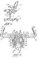
- the chair comprises a base 10, a seat 11 and a back 12.
- the base is mounted on a pedestal which includes an upright spindle 14 projecting upwardly from a five-legged frame adapted to support the chair on a floor or carpet by the use of casters 16 at the end of each leg.
- a pair of arm rests indicated generally at 17 and 18 may be provided extending upwardly on each side of the seat and forwardly of the back.
- the spindle 14 in conventional manner, may include a gas spring lifter which includes an upwardly projecting plunger 20 extending from the top of the spindle through a protective boot 21:
- the gas spring lifter may be operated by an actuator 22 at the side of the chair seen more clearly in Figure 3 which engages a bypass valve through a lever 23. In this manner, the vertical height of the chair may readily be adjusted.
- Such gas spring lifters are conventional.
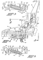
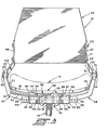
- the plunger of the gas spring lifter is secured through a wedge lock 25 seen in Figure 4 to the base 10.
- the outline of the base in plan, as seen more clearly in Figure 4 is generally T-shape and includes a vertically oriented back wall 27 at the rear of the base which extends completely across the head of the T.
- the ends of the head of the T are closed by end walls 28 and 29 which are in turn connected to somewhat shorter walls 30 and 31, respectively forming the underside of the head of the T as seen in Figure 4.
- Connected both to such walls and to the back wall 27 are forwardly projecting side walls 33 and 34.
- the walls 35 and 36 also provide in cooperation with the outer walls housing for springs 40 and 41, the function and operation of which will hereinafter be described.
- the walls 33 and 35 are interconnected by transverse walls 43 and A.4 as well as the back wall 27, as seen more clearly in Figure 6.
- the walls 36 and 34 are interconnected by transverse walls 46 and 47, as well as the back wall 27, as seen more clearly in Figure 5.
- the wall structure above described for the springs and supporting the chair on top of the gas spring plunger of the spindle comprises a mechanism housing and may be fabricated of aluminum by weldments or cast in metal as a single unit.
- a cross shaft 50 which may be mounted in the various vertical walls within plastic bearings 51.
- the cross shaft extends somewhat beyond the ends of the head of the T as indicated at 53 and 54 and projects into the hubs 55 and 56 of back pivot arms 57 and 58, respectively.
- the projecting ends of the cross shaft within the hubs may be flattened and secured in place by pairs of set screws 60.
- the pivot arms 57 and 58 may be in the form of an aluminum weldment or castings, for example, and extend outwardly and upwardly from beneath the seat 11 to horizontally aligned pivot hubs 62 and 63. From such hubs the back pivots continue upwardly extending initially rearwardly and inwardly as seen at 64 and 65 and then vertically upwardly as seen at 66 and 67.
- the seat back may include a cushion shell shown generally at 69 to which the upper ends of the back pivot arms are connected by fasteners 70 extending through vertically elongated slots 71. In this manner, the seat back may be vertically adjusted.
- the seat back pivot arms form from the cross shaft 50 to the center of hubs 62 and 63 the rear link of a four-bar linkage hereinafter more completely described.
- the hubs 62 and 63 are slightly above the seat bottom which is seen at 73 in Figure 2 and to each side thereof.
- the centers of such hubs are fairly close to the natural body pivot of the user.
- Each hub has journaled therein horizontally extending spindles 75 and 76 which extend outwardly from the tops of seat cradle hangers 77 and 78, respectively.
- Such hangers are secured to the upwardly curved ends of a square tube 80, and from such ends extend slightly outwardly and upwardly to the spindle.
- the hangers may also have a slight dog leg to the rear as seen in Figure 2.
- the square tube is curved upwardly to support removably and adjustably a shell 81 of the seat 11.
- the spindles 75 and 76 are the elements to which the arm rests are connected.
- the spindles 75 and 76 may be journaled in such hubs by shouldered plastic bushings then secured in place by fasteners 83 and 84 extending into holes in the spindles and extending through plastic thrust washers 85.
- the fasteners 83 and 84 may also be used to secure removably in place the arm rests 17 and 18.
- Secured to the square tube and extending forwardly therefrom are two angle members 87 and 88 which complete the seat cradle.
- the two horizontally outwardly extending top flanges of such angles may be employed also to secure removably the seat shell 81 in place. Such adjustment may be obtained by fasteners and slots.
- the seat cradle is rigidly secured to the seat shell which is in turn suspended from the pivots or pintles 75 and 76.
- the seat cradle and arms, generally designated at 90 forms a rigid L-shape link which is another link of such four-bar linkage.
- the seat cradle is pivotally connected to the top of a relatively short front link 92, the sectional configuration of which is more clearly shown in Figures 5 and 6.
- the front link 92 includes a top hub 94 and a bottom somewhat larger hub 95 interconnected by a front web 96.
- the top hub 94 is somewhat longer than the bottom hub an projects over the top of the base side plates 33 and 34 as seen in Figure 3.
- the front link is pivotally connected to the vertical flanges of the angles 87 and 88 of the cradle 90 by fasteners 97.
- the front link is also connected to the forwardly projecting side plates of the base or spring housing by fasteners 98.
- Such fasteners may extend through suitable sleeve and thrust and plastic bearings. In this manner, the front of the cradle is pivoted to the top of the front link which forms another link in such four-bar linkage.
- the base or spring housing 10 which is fixed on top of the gas spring plunger and pivotally connected to the front link as well as a rear link forms the fourth bar of such four-bar linkage.
- the spring 41 is compressed when the seat and back are tilted rearwardly.
- the spring actuator includes a ball socket receiving the ball nose of spring plunger 101 which extends through the wall 47 and has secured thereto on the opposite side of such plate a washer 103.
- the spring plunger may be mounted in such plate on a plastic sleeve bearing and an elastomeric stop 104 is provided between the plate and the spring actuator.
- the spring actuator rocks with the shaft 50 and, as the shaft rocks in a clockwise direction as seen in Figure 5, the spring 41 is compressed. When it rocks in the opposite direction it disengages.
- the compression of the spring may be adjusted by rotation of threaded stud 106 threaded in wall 46.
- the stud includes a ball nose supporting spring retaining washer 107 confining the opposite end of the spring 41.
- the hub 95 of the front link includes a projecting arm 110 which includes a bifurcated hook 111.
- the hook 111 is designed to engage transverse pin 112 on fixture 113 secured to the threaded end of rod 114 extending through a plastic bushing 115 in the plate 43.
- the opposite end of the rod is provided with adjustable lock nuts 117 which contain the spring 40 between the spring retainer 118 and the plate 43. Rotational movement of the front link in a counter clockwise direction as seen in Figure 6 from the position in Figure 6 will compress spring 40. Rotation in a clockwise direction will permit the spring to extend and continued rotation will permit the hook 111 to move away from the transverse pin 112.
- Such springs maintain the seat of the chair in a substantially horizontal or neutral position. Forward tilting of the seat will cause the spring 40 to be compressed while rearward tilting of the seat will cause the spring 41 to be compressed.
- the seat back 12 may be provided with an optional shoulder support indicated at 120.
- the shoulder support may be vertically adjustably mounted on a leaf spring or the like 121 from the shell of the seat back.
- FIGS 7 and 8 Also indicated in Figures 7 and 8 are the interchangeable positions of the arm rests 17 and 18.
- Such arm rests are mounted on vertically extending arms or stanchions 123 and are laterally offset and may be vertically adjustably secured thereto through a multiple tooth or race and clamp mechanism. In this manner, the height of the arm rests may be adjusted.
- Such arm rests may be secured to the outside of the spindles 75 and 76 simply by removing the fasteners 83 and 84 and the associated washers.
- the arm rests may readily be removed and replaced and clamped in position.
- the angular position of the arm rests with respect to a vertical axis or the horizontal disposition of the seat may readily be in this manner adjusted if required.
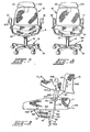
- the arm rests may be interchanged one for the other as seen in comparing Figures 7 and 8 so that a wider ( Figure 7) or more narrow ( Figure 8) dimension is provided between interiors of such arm rests.
- the lower ends of the arms of the arm rests are, of course, provided with suitable holes through which the fasteners 83 and 84 may extend to be locked to the seat cradle spindles projecting through the pivotal seat support. In this way the arms move in relationship to the seat. The result is that as the seat tilts forward and the back comes further forward less arm extends beyond the back rest to interfere with a desk or table edge, whereas, in rear tilt more arm is forward of the back rest.
- the back may move to the phanton line position seen at 130 in Figure 2.
- the seat pivot for the suspended cradle also moves to the position 131 seen in Figure 2 through the arc indicated at 132.
- the front link is drawn rearwardly through the arc 134 causing the seat to tilt rearwardly and upwardly through the arc indicated by the arrows 135.
- As indicated such ratio is approximately on the order of 1 to 3 for a seat/back tilt ratio.
- the back pivot arm moves forwardly about the cross shaft 50 moving the seat to the phantom line position 137 and moving the principal seat pivot support or spindles through the arc 138 for rocking forward to the extent indicated by the arrows 139.
- This then pivots the front link 92 forwardly through the arc 140 against the pressure of the spring 40 tilting the seat forwardly and downward through the arc indicated by the arrows 141.
- the tilt ratio of the back to the seat may be on the order of 2 to 1, respectively.
- FIG. 9 there is illustrated schematically the four-bar linkage which comprises the rear link 58, a top rigid L-shape link 78, 88, a relatively short front link 92 and a fixed or bottom link 10.
- the seat back may be adjusted vertically as indicated by the arrows 150.
- the arm rests may be adjusted vertically as indicated by the arrows 151, and may be adjusted angularly about the seat pivot spindles as indicated by the arrows 152.
- arm rests 17 and 18 may be interchanged as indicated by the arrows 153 to provide the more narrow or wider seat seen in Figures 7 and 8.
- the entire seat may be vertically adjusted through the gas spring as indicated by the arrows 154.
- the seat may be adjusted to the front or rear in order to change seat depth in reference to the back, as indicated by the arrows 155.
- a seat which includes the four-bar linkage indicated which includes a fixed link 10 having fixed pivots at each end.
- the front link pivots through the arc 156 in conjunction with the fore and aft pivot of the seat support spindles indicated by the arc 157.
- the entire mechanism is balanced in a neutral or a position wherein the seat is substantially horizontal both by the weight of the user and by the springs 40 and 41.
Landscapes
- Health & Medical Sciences (AREA)
- Dentistry (AREA)
- General Health & Medical Sciences (AREA)
- Chairs Characterized By Structure (AREA)
- Chairs For Special Purposes, Such As Reclining Chairs (AREA)
- Seats For Vehicles (AREA)
Applications Claiming Priority (2)
| Application Number | Priority Date | Filing Date | Title |
|---|---|---|---|
| US61851884A | 1984-06-08 | 1984-06-08 | |
| US618518 | 1984-06-08 |
Publications (2)
| Publication Number | Publication Date |
|---|---|
| EP0164266A2 true EP0164266A2 (fr) | 1985-12-11 |
| EP0164266A3 EP0164266A3 (fr) | 1987-04-01 |
Family
ID=24478046
Family Applications (1)
| Application Number | Title | Priority Date | Filing Date |
|---|---|---|---|
| EP85303993A Withdrawn EP0164266A3 (fr) | 1984-06-08 | 1985-06-05 | Siège |
Country Status (6)
| Country | Link |
|---|---|
| EP (1) | EP0164266A3 (fr) |
| JP (1) | JPS6145707A (fr) |
| KR (1) | KR860000050A (fr) |
| AU (1) | AU4316385A (fr) |
| CA (1) | CA1235055A (fr) |
| ES (1) | ES287267Y (fr) |
Cited By (8)
| Publication number | Priority date | Publication date | Assignee | Title |
|---|---|---|---|---|
| US4761033A (en) * | 1986-05-26 | 1988-08-02 | Drabert Sohne Gmbh & Co. | Chair |
| US4804227A (en) * | 1986-12-15 | 1989-02-14 | Ahrend-Cirkel B.V. | Point-synchronized adjustment device for office chairs |
| DE3737491C2 (de) * | 1987-11-05 | 2003-03-20 | Wilkhahn Wilkening & Hahne | Stuhl |
| DE3737492C2 (de) * | 1987-11-05 | 2003-03-27 | Wilkhahn Wilkening & Hahne | Stuhl mit vier Drehgelenken |
| US6802566B2 (en) | 2000-09-28 | 2004-10-12 | Formway Furniture Limited | Arm assembly for a chair |
| US6840582B2 (en) | 2002-05-14 | 2005-01-11 | Formway Furniture Limited | Height adjustable arm assembly |
| CN113303613A (zh) * | 2012-09-20 | 2021-08-27 | 斯迪尔科斯公司 | 椅子组件 |
| US11253077B2 (en) | 2016-12-21 | 2022-02-22 | Kokuyo Co., Ltd. | Chair with return force mechanism |
Families Citing this family (14)
| Publication number | Priority date | Publication date | Assignee | Title |
|---|---|---|---|---|
| KR100334316B1 (ko) | 1992-06-15 | 2002-10-11 | 헤르만밀러인코퍼레이티드 | 사무용의자의지지장치및제조방법 |
| USD460300S1 (en) | 2000-09-28 | 2002-07-16 | Formway Furniture Limited | Slotted seat panel for a chair |
| USD463144S1 (en) | 2000-09-28 | 2002-09-24 | Formway Furniture Limited | Chair |
| AUPR054400A0 (en) | 2000-09-29 | 2000-10-26 | Formway Furniture Limited | A castor |
| CN102772053A (zh) | 2007-01-29 | 2012-11-14 | 赫尔曼米勒有限公司 | 座位结构及其使用方法 |
| JP4796087B2 (ja) * | 2008-03-31 | 2011-10-19 | 株式会社岡村製作所 | 椅子における背凭れ等の傾動装置 |
| JP2010104562A (ja) * | 2008-10-30 | 2010-05-13 | Okamura Corp | 椅子 |
| JP5989999B2 (ja) * | 2012-01-27 | 2016-09-07 | 株式会社岡村製作所 | 椅子 |
| US10021984B2 (en) | 2015-04-13 | 2018-07-17 | Steelcase Inc. | Seating arrangement |
| US10194750B2 (en) | 2015-04-13 | 2019-02-05 | Steelcase Inc. | Seating arrangement |
| US11259637B2 (en) | 2015-04-13 | 2022-03-01 | Steelcase Inc. | Seating arrangement |
| US10966527B2 (en) | 2017-06-09 | 2021-04-06 | Steelcase Inc. | Seating arrangement and method of construction |
| ES3035683T3 (en) | 2019-02-21 | 2025-09-08 | Steelcase Inc | Body support member |
| US11357329B2 (en) | 2019-12-13 | 2022-06-14 | Steelcase Inc. | Body support assembly and methods for the use and assembly thereof |
Family Cites Families (2)
| Publication number | Priority date | Publication date | Assignee | Title |
|---|---|---|---|---|
| US2830650A (en) * | 1953-10-23 | 1958-04-15 | Lorenz Anton | Article of repose for supporting the body of a person |
| US4131260A (en) * | 1977-05-09 | 1978-12-26 | Center For Design Research And Development N.V. | Chair seat mount which permits the seat to tilt forward |
-
1985
- 1985-05-30 AU AU43163/85A patent/AU4316385A/en not_active Abandoned
- 1985-06-05 EP EP85303993A patent/EP0164266A3/fr not_active Withdrawn
- 1985-06-07 JP JP60122836A patent/JPS6145707A/ja active Pending
- 1985-06-07 ES ES1985287267U patent/ES287267Y/es not_active Expired
- 1985-06-07 KR KR1019850003964A patent/KR860000050A/ko not_active Withdrawn
- 1985-06-07 CA CA000483432A patent/CA1235055A/fr not_active Expired
Cited By (14)
| Publication number | Priority date | Publication date | Assignee | Title |
|---|---|---|---|---|
| US4761033A (en) * | 1986-05-26 | 1988-08-02 | Drabert Sohne Gmbh & Co. | Chair |
| US4804227A (en) * | 1986-12-15 | 1989-02-14 | Ahrend-Cirkel B.V. | Point-synchronized adjustment device for office chairs |
| DE3737491C2 (de) * | 1987-11-05 | 2003-03-20 | Wilkhahn Wilkening & Hahne | Stuhl |
| DE3737492C2 (de) * | 1987-11-05 | 2003-03-27 | Wilkhahn Wilkening & Hahne | Stuhl mit vier Drehgelenken |
| US6910741B2 (en) | 2000-09-28 | 2005-06-28 | Formway Furniture Limited | Lumbar support |
| US6817667B2 (en) | 2000-09-28 | 2004-11-16 | Formway Furniture Limited | Reclinable chair |
| US6874852B2 (en) | 2000-09-28 | 2005-04-05 | Formway Furniture Limited | Lumbar support |
| US6908159B2 (en) | 2000-09-28 | 2005-06-21 | Formway Furniture Limited | Seat for a reclining office chair |
| US6802566B2 (en) | 2000-09-28 | 2004-10-12 | Formway Furniture Limited | Arm assembly for a chair |
| US7441839B2 (en) | 2000-09-28 | 2008-10-28 | Formway Furniture Limited | Reclinable chair |
| US7798573B2 (en) | 2000-09-28 | 2010-09-21 | Formway Furniture Limited | Reclinable chair |
| US6840582B2 (en) | 2002-05-14 | 2005-01-11 | Formway Furniture Limited | Height adjustable arm assembly |
| CN113303613A (zh) * | 2012-09-20 | 2021-08-27 | 斯迪尔科斯公司 | 椅子组件 |
| US11253077B2 (en) | 2016-12-21 | 2022-02-22 | Kokuyo Co., Ltd. | Chair with return force mechanism |
Also Published As
| Publication number | Publication date |
|---|---|
| CA1235055A (fr) | 1988-04-12 |
| JPS6145707A (ja) | 1986-03-05 |
| ES287267Y (es) | 1986-07-16 |
| KR860000050A (ko) | 1986-01-25 |
| EP0164266A3 (fr) | 1987-04-01 |
| AU4316385A (en) | 1985-12-12 |
| ES287267U (es) | 1985-12-16 |
Similar Documents
| Publication | Publication Date | Title |
|---|---|---|
| EP0164266A2 (fr) | Siège | |
| US5009466A (en) | Reclining chair | |
| US4479679A (en) | Body weight chair control | |
| CA1315662C (fr) | Chaise a basculement synchronise | |
| US4880270A (en) | Work station system | |
| US5261723A (en) | Ergonomic chair having the seat at a varying position | |
| JPH04746Y2 (fr) | ||
| US4560199A (en) | Recliner chair | |
| EP0149041B1 (fr) | Mécanisme pour chaise inclinable | |
| US4752101A (en) | Tilt control arrangement for office furniture chair | |
| US5042876A (en) | Controller for seating and the like | |
| US4192549A (en) | Weeelchair tilt cradle | |
| JPH034807A (ja) | 椅子、特に作業用または事務用の椅子 | |
| WO2002102199B1 (fr) | Chaise ergonomique amelioree | |
| DK156756B (da) | Haeldningsindstillelig stol | |
| JPH0628609B2 (ja) | 椅 子 | |
| US20070210634A1 (en) | Ergonomic Chair | |
| JPH05500619A (ja) | 作業ステーシヨンシステム | |
| US4438978A (en) | Tilt back mechanism for a chair | |
| JP4627931B2 (ja) | 椅子の背もたれの支持機構 | |
| CA1315186C (fr) | Fauteuil a accoudoirs specialement profiles | |
| JPH0217168B2 (fr) | ||
| JP2797273B2 (ja) | 背もたれ付き椅子 | |
| JPS6223645Y2 (fr) | ||
| JPH02172410A (ja) | 椅子 |
Legal Events
| Date | Code | Title | Description |
|---|---|---|---|
| PUAI | Public reference made under article 153(3) epc to a published international application that has entered the european phase |
Free format text: ORIGINAL CODE: 0009012 |
|
| AK | Designated contracting states |
Designated state(s): AT BE CH DE FR GB IT LI NL SE |
|
| PUAL | Search report despatched |
Free format text: ORIGINAL CODE: 0009013 |
|
| AK | Designated contracting states |
Kind code of ref document: A3 Designated state(s): AT BE CH DE FR GB IT LI NL SE |
|
| STAA | Information on the status of an ep patent application or granted ep patent |
Free format text: STATUS: THE APPLICATION IS DEEMED TO BE WITHDRAWN |
|
| 18D | Application deemed to be withdrawn |
Effective date: 19871002 |
|
| RIN1 | Information on inventor provided before grant (corrected) |
Inventor name: DIFFRIENT, NIELS |