EP0164305A1 - Anordnung zum Abtrennen von Gruppen verschiedener Länge aus Gegenständen - Google Patents
Anordnung zum Abtrennen von Gruppen verschiedener Länge aus Gegenständen Download PDFInfo
- Publication number
- EP0164305A1 EP0164305A1 EP85810160A EP85810160A EP0164305A1 EP 0164305 A1 EP0164305 A1 EP 0164305A1 EP 85810160 A EP85810160 A EP 85810160A EP 85810160 A EP85810160 A EP 85810160A EP 0164305 A1 EP0164305 A1 EP 0164305A1
- Authority
- EP
- European Patent Office
- Prior art keywords
- pick
- arrangement according
- adjustment gear
- separating
- floor
- Prior art date
- Legal status (The legal status is an assumption and is not a legal conclusion. Google has not performed a legal analysis and makes no representation as to the accuracy of the status listed.)
- Granted
Links
- 235000015895 biscuits Nutrition 0.000 claims description 4
- 238000006073 displacement reaction Methods 0.000 claims 2
- 230000007246 mechanism Effects 0.000 abstract description 4
- 235000015173 baked goods and baking mixes Nutrition 0.000 description 3
- 238000004806 packaging method and process Methods 0.000 description 3
- 230000005540 biological transmission Effects 0.000 description 2
- 230000008878 coupling Effects 0.000 description 2
- 238000010168 coupling process Methods 0.000 description 2
- 238000005859 coupling reaction Methods 0.000 description 2
- 238000005259 measurement Methods 0.000 description 2
- 230000015572 biosynthetic process Effects 0.000 description 1
- 230000001419 dependent effect Effects 0.000 description 1
- 238000010586 diagram Methods 0.000 description 1
- 238000005516 engineering process Methods 0.000 description 1
- 238000000034 method Methods 0.000 description 1
- 238000011144 upstream manufacturing Methods 0.000 description 1
- 238000005303 weighing Methods 0.000 description 1
Images

Classifications
-
- B—PERFORMING OPERATIONS; TRANSPORTING
- B65—CONVEYING; PACKING; STORING; HANDLING THIN OR FILAMENTARY MATERIAL
- B65B—MACHINES, APPARATUS OR DEVICES FOR, OR METHODS OF, PACKAGING ARTICLES OR MATERIALS; UNPACKING
- B65B23/00—Packaging fragile or shock-sensitive articles other than bottles; Unpacking eggs
- B65B23/10—Packaging biscuits
- B65B23/12—Arranging, feeding or orientating the biscuits to be packaged
- B65B23/14—Forming groups of biscuits
-
- B—PERFORMING OPERATIONS; TRANSPORTING
- B65—CONVEYING; PACKING; STORING; HANDLING THIN OR FILAMENTARY MATERIAL
- B65G—TRANSPORT OR STORAGE DEVICES, e.g. CONVEYORS FOR LOADING OR TIPPING, SHOP CONVEYOR SYSTEMS OR PNEUMATIC TUBE CONVEYORS
- B65G47/00—Article or material-handling devices associated with conveyors; Methods employing such devices
- B65G47/02—Devices for feeding articles or materials to conveyors
- B65G47/04—Devices for feeding articles or materials to conveyors for feeding articles
- B65G47/06—Devices for feeding articles or materials to conveyors for feeding articles from a single group of articles arranged in orderly pattern, e.g. workpieces in magazines
- B65G47/08—Devices for feeding articles or materials to conveyors for feeding articles from a single group of articles arranged in orderly pattern, e.g. workpieces in magazines spacing or grouping the articles during feeding
- B65G47/082—Devices for feeding articles or materials to conveyors for feeding articles from a single group of articles arranged in orderly pattern, e.g. workpieces in magazines spacing or grouping the articles during feeding grouping articles in rows
Definitions
- the present invention relates to an arrangement for separating groups of different lengths according to the preamble of independent claim 1.
- the disk-shaped biscuits are conveyed upright to a measuring station, where they are grouped.
- the grouping is done either by a counting process, a length measurement or by weighing. While individual biscuits have only slight differences in weight, their thickness can vary considerably. If the length of the group is therefore only determined, the number can vary considerably. Nevertheless, the formation of groups by length measurement is desired because this simplifies packaging operations.
- a measuring device is described, for example, in US Pat. No. 3,037,610.
- the disc-shaped, flat baked goods coming irregularly from the oven are layered, as is generally known in the packaging industry, into a stream of upright baked goods and transported onward, as is also described in the aforementioned US Pat. No. 3,037,610.
- the stream S thus obtained accumulates on a pick-up tray 10 in its upstream end position.
- a retainer 21 in the straight continuation of the guide support there is a receiving base 22 for the further transport of the grouped baked goods, which is indicated without the necessary movement elements for the further transport.
- Such an arrangement for further transport is e.g. a recording table as shown in CH-A 380 635.
- a separating sword 23 is located in the phase shown above the current S of objects G.
- the separating sword 23 To change the length of the separated stack, the separating sword 23 must be moved to the left against the pick-up floor 10 with the first adjustment gear 40.
- the desired positioning of the first object of the separated stack with respect to the holding wall 11 of the receiving plate 22 in relation to the set group length is ensured by a second adjusting mechanism 50 and a third adjusting mechanism 60, i.e. the downstream end of the guide pad 20 is moved to the left together with the pick-up tray 10, the retainer 21 and the separating sword 23.
- the stack located between the separating sword 23 and the pick-up floor 10 then corresponds exactly to the group length.
- a control is provided from a driven cam disk arrangement 30, a sliding carriage 33 being moved back and forth in accordance with the double arrow A by means of a first scanning roller on a first cam disk via a first angle lever 31 and a connecting rod 32 that are fixed to the frame becomes.
- the pick-up tray 10 is rigidly attached to this sliding carriage 33.
- a horizontal guide 34 for the separating sword 23 is driven in a vertically movable manner according to the double arrow B on a second cam disc with a scanning roller on a further linkage, not shown.
- a third cam disc with a scanning roller on a linkage causes the vertical movement according to double arrow C for the retainer 21, which is guided in a horizontal guide 24.
- the three cams mentioned can be attached to a common drive shaft and rotated together, as is known from drive technology.
- a first adjustment gear 40, a second adjustment gear 50 and a third adjustment gear 60 are provided for adjusting the group length.
- a square shaft 41 is fixed to the frame in two bearing points 42, 43 fixed to the frame.
- a threaded sleeve 44 is displaceably guided on this square shaft 41. With their external thread, the threaded sleeve 44 is screwed into a guide rod 45 with a threaded hole 46.
- the sliding carriage 33 is rotatably mounted on the threaded sleeve 44 by means of a rotary bearing 29, so that the threaded sleeve 44 can also perform a movement according to the arrow A due to the movement of the sliding carriage 33.
- the guide rod 45 serves to support two parallel rods 47, 48 of a parallelogram transmission, both of which other joints are on the holding rod 49 of the separating sword 23. Together with the vertically movably driven horizontal guide 34, the separating sword is pushed into the stream S of the objects and pulled out again when the horizontal guide 34 moves according to arrow B. As usual, the separating sword 23 is fastened to the holding rod 49 with a spiral spring 25 in order to be able to evade resistance when hitting an object.
- a horizontally displaceable holder 52 with which the guide support 20 is rigidly connected, serves for the mounting of two parallel rods 53, 54 for a further parallelogram gear for the vertical movement of the retainer 21 when the horizontal guide 24 moves according to arrow C.
- a third adjustment gear 60 is provided in the corresponding drive element.
- An adjusting nut 63 provided on the connecting rod 64 for actuating the angle lever 31 is screwed onto a threaded spindle 62 rotatably supported on the swivel lever 61.
- the threaded spindle 62 By turning the threaded spindle 62, the distance between the adjusting nut 63 and thus the point of engagement of the connecting rod 64 on the swivel lever 61 and the fixed pivot point 65 of the swivel lever 61 changes, so that the constant stroke of the swivel lever 61 caused by the scanning roller 66 has a differently large stroke Connecting rod 64 causes the same at a different starting position.
- FIG. 2 shows two possible end positions of the two coupling ends 31a, 31b of the two-armed lever 31.
- the positions Ia, Ib and IIa, IIb mean these end positions and the positions IIIa, IIIb the respective pivot end positions.
- the two-armed lever 31 in position Ia, Ib between points Ia-IIIa and Ib-IIIb and in position IIa, IIb between points IIa-IIIa and IIb-IIIb moves when the point of attack of the adjusting nut 63 with the connecting rod 64 is correspondingly shifted from point I to point II, and thus when the pivot lever 61 is actuated by a cam and scanning roller 66, either point I, arc D to point III or point II the sheet E to point III described.
Landscapes
- Engineering & Computer Science (AREA)
- Mechanical Engineering (AREA)
- Sheets, Magazines, And Separation Thereof (AREA)
- Specific Conveyance Elements (AREA)
- Branching, Merging, And Special Transfer Between Conveyors (AREA)
- Special Conveying (AREA)
- Sorting Of Articles (AREA)
Abstract
Description
- Die vorliegende Erfindung betrifft eine Anordnung zum Abtrennen von Gruppen verschiedener Länge gemäss dem Oberbegriff des unabhängigen Patentanspruches 1.
- Beim Verpacken von Biskuits werden die scheibenförmigen Biskuits hochkant stehend zu einer Messstation gefördert, wo sie gruppiert werden. Die Gruppierung erfolgt entweder durch einen Zählvorgang, eine Längenmessung oder durch Wägen. Während einzelne Biskuits nur geringe Gewichtsunterschiede haben, kann deren Dicke erheblich variieren. Wenn deshalb nur eine Längenbestimmung der Gruppe erfolgt, so kann die Anzahl erheblich variieren. Trotzdem wird die Bildung von Gruppen durch eine Längenmessung gewünscht, weil dies die Verpackungsoperationen vereinfacht. Eine solche Abmessvorrichtung ist beispielsweise im US-Patent 3 037 610 beschrieben.
- Demgemäss ist es eine Aufgabe der Erfindung, bei einer Anordnung zum Abtrennen von Gruppen von scheibenförmigen, gestapelten Gegenständen eine Verstellung der Gruppenlänge mit einfachen Bedienungsmitteln zu schaffen.
- Erfindungsgemäss wird dies durch die Merkmale im kennzeichnenden Teil des unabhängigen Patentanspruches 1 erreicht. In den abhängigen Patentansprüchen sind besonders vorteilhafte Ausführungsformen beschrieben.
- Ein Ausführungsbeispiel der Erfindung ist in der Zeichnung dargestellt. Es zeigen:
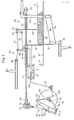
- Fig. 1 ein schematisch dargestelltes Getriebeschema, und
- Fig. 2 einen Ausschnitt aus Fig. 1 in vergrössertem Massstab zur Darstellung der Antriebskopplung.
- Die unregelmässig vom Backofen kommenden, scheibenförmigen, flachen Backwaren werden wie allgemein in der Verpackungsindustrie bekannt ist, zu einem Strom hochkant gestellter Backwaren geschichtet und weitertransportiert, wie im vorgenannten US-Patent Nr. 3 037 610 auch beschrieben ist.
- Der damit erhaltene Strom S staut sich an einem Abholboden 10 in seiner stromaufwärtigen Endlage. An derselben Stelle, die durch das stromabwärtige Ende der Führungsauflage 20 gekennzeichnet ist, befindet sich ein Rückhalter 21 und in der geradlinigen Fortsetzung der Führungsauflage liegt ein Aufnahmeboden 22 für den Weitertransport der gruppierten Backwaren, der andeutungsweise ohne die notwendigen Bewegungselemente für den Weitertransport gezeichnet ist. Eine solche Anordnung für den Weitertransport ist z.B. ein Aufnahmetisch, wie er in der CH-A 380 635 dargestellt ist. Ein Trennschwert 23 befindet sich in der dargestellten Phase über dem Strom S von Gegenständen G.
- Zur Veränderung der Länge des abgetrennten Stapels muss das Trennschwert 23 mit dem ersten Verstellgetriebe 40 nach links gegen den Abholboden 10 verschoben werden. Die zur eingestellten Gruppenlänge gewünschte Positionierung des ersten Gegenstandes des abgetrennten Stapels bezüglich der Haltewand 11 des Aufnahmebcdens 22, wird durch ein zweites Verstellgetriebe 50 und drittes Verstellgetriebe 60 gewährleistet, d.h. das stromabwärtige Ende der Führungsauflage 20 wird zusammen mit dem Abholboden 10, dem Rückhalter 21 und dem Trennschwert 23 nach links verschoben. Der zwischen dem Trennschwert 23 und dem Abholboden 10 befindliche Stapel entspricht dann genau der Gruppenlänge.
- In für diese bekannten Elemente üblicher Weise ist eine Steuerung von einer angetriebenen Kurvenscheibenanordnung 30 aus vorhanden, wobei mittels einer ersten Abtastrolle auf einer ersten Kurvenscheibe über einen ersten, gestellfest gelagerten Winkelhebel 31 und eine Pleuelstange 32 ein Verschiebeschlitten 33 gemäss dem Doppelpfeil A hin- und herbewegt wird. An diesem Verschiebeschlitten 33 ist der Abholboden 10 starr befestigt.
- Auf einer zweiten Kurvenscheibe mit einer Abtastrolle an einem weiteren nicht dargestellten Gestänge ist eine Horizontalführung 34 für das Trennschwert 23 vertikalbeweglich gemäss dem Doppelpfeil B angetrieben.
- Eine dritte Kurvenscheibe mit einer Abtastrolle an einem ebenfalls nicht dargestellten Gestänge bewirkt die vertikale Bewegung gemäss Doppelpfeil C für den Rückhalter 21, der in einer Horizontalführung 24 geführt ist.
- Die drei genannten Kurvenscheiben können auf einer gemeinsamen Antriebswelle befestigt sein und gemeinsam rotiert werden, wie aus der Antriebstechnik bekannt ist.
- Für die Verstellung der Gruppenlänge sind ein erstes Verstellgetriebe 40, ein zweites Verstellgetriebe 50 und ein drittes Verstellgetriebe 60 vorhanden.
- Für das erste Verstellgetriebe 40 und das zweite Verstellgetriebe 50 ist eine Vierkantwelle 41 in zwei gestellfesten Lagerstellen 42, 43 gestellfest gelagert. Als erstes Verstellgetriebe 40 ist eine Gewindehülse 44 auf dieser Vierkantwelle 41 verschieblich geführt. Mit deren Aussengewinde ist die Gewindehülse 44 in einem Führungsstab 45 mit Gewindeloch 46 eingeschraubt. Der Verschiebeschlitten 33 ist mittels eines Drehlagers 29 rotierbar auf der Gewindehülse 44 gelagert, so dass die Gewindehülse 44 eine durch die Bewegung des Verschiebeschlittens 33 bedingt, ebenfalls eine Bewegung gemäss dem Pfeil A ausführen kann.
- Durch Drehen des Vierkantstabes 41 wird somit die Lage des Führungsstabes 45 bezüglich des Drehlagers 29 verändert und dadurch der Abstand zwischen dem Abholboden 10 und dem Trennschwert 23.
- Der Führungsstab 45 dient zur Lagerung von zwei parallelen Stäben 47, 48 eines Parallelogrammgetriebes, dessen beide übrigenGelenke sich am Haltestab 49 des Trennschwertes 23 befinden. Zusammen mit der vertikalbeweglich angetriebenen Horizontalführung 34 wird damit das Trennschwert bei Bewegung der Horizontalführung 34 gemäss Pfeil B in den Strom S der Gegenstände hineingestossen und wieder herausgezogen. Wie üblich, ist das Trennschwert 23 mit einer Spiralfeder 25 am Haltestab 49 befestigt, um bei einem Widerstand beim Auftreffen auf einen Gegenstand ausweichen zu können.
- In gleicher Weise werden Führungsauflage 20 und Rückhalter 21 mittels einer weiteren Gewindehülse 51 im Verstellgetriebe 50 verschoben. Ein horizontalverschieblich geführter Halter 52, mit dem die Führungsauflage 20 starr verbunden ist, dient für die Lagerung zweier paralleler Stäbe 53, 54 für ein weiteres Parallelogrammgetriebe zur Vertikalbewegung des Rückhalters 21 bei einer Bewegung der Horizontalführung 24 gemäss Pfeil C.
- Durch eine Drehbewegung des Vierkantstabes 41 kann nun erreicht werden, dass sich Trennschwert 23, Führungsauflage 20 und Rückhalter 21 um gleiche Beträge nach links in der Figur bewegen, um so die Abstände zu verkleinern.
- Damit sich nun aber auch der Abholboden 10 um einen entsprechenden Betrag verschiebt und um gleichzeitig auch den Hub des Abholbodens 10 zu verändern, ist im entsprechenden Antriebselement ein drittes Verstellgetriebe 60 vorgesehen.
- Auf einer drehbar auf dem Schwenkhebel 61 gehalterten Gewindespindel 62 ist eine an der Pleuelstange 64 zur Betätigung des Winkelhebels 31 vorhandene Verstellmutter 63 aufgeschraubt. Durch Drehen der Gewindespindel 62 verändert sich der Abstand zwischen der Verstellmutter 63 und damit der Angriffspunkt der Pleuelstange 64 am Schwenkhebel 61 und dem gestellfesten Drehpunkt 65 des Schwenkhebels 61, so dass der durch die Abtastrolle 66 bewirkte konstante Hub des Schwenkhebels 61 einen unterschiedlich grossen Hub der Pleuelstange 64 bei einer anderen Ausgangslage derselben bewirkt.
- In Fig. 2 sind zwei mögliche Endstellungen der beiden Kopplungsenden 31a, 31b des zweiarmigen Hebels 31 dargestellt. Dabei bedeuten die Stellen Ia, Ib und IIa, IIb diese Endstellen und die Stellen IIIa, IIIb die jeweiligen Schwenkendlagen. Somit wird der zweiarmige Hebel 31 in der Stelle Ia, Ib zwischen den Punkten Ia-IIIa bzw. Ib-IIIb und in der Stelle IIa, IIb zwischen den Punkten IIa-IIIa bzw. IIb-IIIb bewegt, wenn der Angriffspunkt der Verstellmutter 63 mit der Pleuelstange 64 entsprechend von der Stelle I zur Stelle II verschoben wird, und damit wird bei Betätigung des Schwenkhebels 61 durch Kurvenscheibe und Abtastrolle 66 entweder der Punkt I den Bogen D zum Punkt III oder der Punkt II den Bogen E zum Punkt III beschrieben.
- Mit zwei Zahnrädern 70, 71, zwei Kardangelenken 72, 73 und über ein Doppelkegelgetriebe 74 lassen sich somit sämtliche Einstellungen von einer zentralen Stelle aus, die durch den Motor 75 symbolisch dargestellt ist, auf einfache Weise und korrekt durchführen.
Claims (8)
Applications Claiming Priority (2)
| Application Number | Priority Date | Filing Date | Title |
|---|---|---|---|
| CH2270/84 | 1984-05-09 | ||
| CH2270/84A CH663591A5 (de) | 1984-05-09 | 1984-05-09 | Anordnung zum abtrennen von gruppen verschiedener laenge von gegenstaenden. |
Publications (2)
| Publication Number | Publication Date |
|---|---|
| EP0164305A1 true EP0164305A1 (de) | 1985-12-11 |
| EP0164305B1 EP0164305B1 (de) | 1987-11-19 |
Family
ID=4229838
Family Applications (1)
| Application Number | Title | Priority Date | Filing Date |
|---|---|---|---|
| EP85810160A Expired EP0164305B1 (de) | 1984-05-09 | 1985-04-12 | Anordnung zum Abtrennen von Gruppen verschiedener Länge aus Gegenständen |
Country Status (6)
| Country | Link |
|---|---|
| US (1) | US4828101A (de) |
| EP (1) | EP0164305B1 (de) |
| JP (1) | JPS60235684A (de) |
| BR (1) | BR8501870A (de) |
| CH (1) | CH663591A5 (de) |
| DE (1) | DE3561001D1 (de) |
Cited By (1)
| Publication number | Priority date | Publication date | Assignee | Title |
|---|---|---|---|---|
| WO1990012745A1 (de) * | 1989-04-22 | 1990-11-01 | Syspack S.A. | Verfahren zum transportieren und aufstapeln von flachen gegenständen, insbesondere von flachbeuteln, sowie vorrichtung zur durchführung dieses verfahrens |
Families Citing this family (9)
| Publication number | Priority date | Publication date | Assignee | Title |
|---|---|---|---|---|
| US5018727A (en) * | 1990-05-25 | 1991-05-28 | Cornell Daniel M | Three in one exercise bench |
| US5421700A (en) * | 1993-04-29 | 1995-06-06 | Tension Envelope Corporation | Envelope flap up pick and place apparatus and method |
| JP4318322B2 (ja) * | 1993-05-07 | 2009-08-19 | グラプハ−ホルディング・アクチエンゲゼルシヤフト | 並列して起立している刷紙に対して垂直方向で指向して堆積体を形成するための装置 |
| CH688128A5 (de) * | 1993-06-21 | 1997-05-30 | Styner & Bienz Ag | Verfahren zum Zufuehren und Vorschieben eines Streifens und Streifenanleger zur Durchfuehrung dieses Verfahrens. |
| IT1294101B1 (it) * | 1997-07-18 | 1999-03-22 | Sasib Beverage S P A Ora Sasib | Procedimento e dispositivo di arresto ammortizzato ed accompagnamento di contenitori, in linea di trasporto per contenitori. |
| US6089000A (en) * | 1998-10-05 | 2000-07-18 | Kinematic Automation, Inc. | Programmable device packaging method and system |
| ATE367341T1 (de) | 2000-04-28 | 2007-08-15 | Siemens Ag | Intelligente vereinzelungsförderanlage mit selektivem votrieb |
| US7470102B2 (en) * | 2001-07-27 | 2008-12-30 | C.G. Bretting Manufacturing Co., Inc. | Apparatus and method for insertion of separating means into a forming stack of sheets discharged from a starwheel assembly |
| DE102012204027B4 (de) * | 2012-03-14 | 2024-10-24 | Krones Ag | Transfereinheit zur horizontalen Verschiebung von Artikellagen zwischen benachbarten Modulen |
Citations (2)
| Publication number | Priority date | Publication date | Assignee | Title |
|---|---|---|---|---|
| CH380635A (de) * | 1960-12-02 | 1964-07-31 | Sig Schweiz Industrieges | Vorrichtung zum Trennen von aneinandergereihten Gegenständen |
| CH444015A (fr) * | 1966-01-10 | 1967-09-15 | Baker Perkins Ltd | Appareil pour séparer d'une colonne continue de biscuits un lot d'une longueur inférieure à un maximum donné |
Family Cites Families (6)
| Publication number | Priority date | Publication date | Assignee | Title |
|---|---|---|---|---|
| US2954881A (en) * | 1958-03-24 | 1960-10-04 | Forgrove Mach | Separation of articles from a stack |
| US3037610A (en) * | 1959-10-06 | 1962-06-05 | Packman Machinery Ltd | Method and apparatus for handling biscuits and the like |
| US4018031A (en) * | 1972-05-19 | 1977-04-19 | Marcal Paper Mills, Inc. | Article packaging machine |
| US4098392A (en) * | 1976-10-26 | 1978-07-04 | Greene William F | Potato chips processing machine |
| CH652674A5 (de) * | 1981-10-15 | 1985-11-29 | Sig Schweiz Industrieges | Vorrichtung zum aufteilen von in einer reihe zulaufenden gegenstaenden und verfahren zum betrieb der vorrichtung. |
| CH653632A5 (de) * | 1982-01-21 | 1986-01-15 | Sig Schweiz Industrieges | Verfahren und vorrichtung zum gruppieren von gegenstaenden und anwendung des verfahrens. |
-
1984
- 1984-05-09 CH CH2270/84A patent/CH663591A5/de not_active IP Right Cessation
-
1985
- 1985-04-12 EP EP85810160A patent/EP0164305B1/de not_active Expired
- 1985-04-12 DE DE8585810160T patent/DE3561001D1/de not_active Expired
- 1985-04-18 BR BR8501870A patent/BR8501870A/pt not_active IP Right Cessation
- 1985-04-26 JP JP60089101A patent/JPS60235684A/ja active Pending
- 1985-05-08 US US06/731,955 patent/US4828101A/en not_active Expired - Fee Related
Patent Citations (2)
| Publication number | Priority date | Publication date | Assignee | Title |
|---|---|---|---|---|
| CH380635A (de) * | 1960-12-02 | 1964-07-31 | Sig Schweiz Industrieges | Vorrichtung zum Trennen von aneinandergereihten Gegenständen |
| CH444015A (fr) * | 1966-01-10 | 1967-09-15 | Baker Perkins Ltd | Appareil pour séparer d'une colonne continue de biscuits un lot d'une longueur inférieure à un maximum donné |
Cited By (1)
| Publication number | Priority date | Publication date | Assignee | Title |
|---|---|---|---|---|
| WO1990012745A1 (de) * | 1989-04-22 | 1990-11-01 | Syspack S.A. | Verfahren zum transportieren und aufstapeln von flachen gegenständen, insbesondere von flachbeuteln, sowie vorrichtung zur durchführung dieses verfahrens |
Also Published As
| Publication number | Publication date |
|---|---|
| EP0164305B1 (de) | 1987-11-19 |
| BR8501870A (pt) | 1985-12-17 |
| CH663591A5 (de) | 1987-12-31 |
| JPS60235684A (ja) | 1985-11-22 |
| DE3561001D1 (en) | 1987-12-23 |
| US4828101A (en) | 1989-05-09 |
Similar Documents
| Publication | Publication Date | Title |
|---|---|---|
| EP0170613B1 (de) | Vorrichtung zum Abtrennen von Gruppen bestimmter Länge von einem Stapel kontinuierlich zugeführter Gegenstände | |
| EP0438109B1 (de) | Trennvorrichtung für im wesentlichen quaderförmige Körper aus tiefgefrorenen Lebens- oder Futtermitteln | |
| DE69317262T2 (de) | Variable Wägeplattform | |
| DE4132333C2 (de) | Koordinatenmeßgerät | |
| DE1284354B (de) | Vorrichtung zum Umsetzen von Gegenstaenden | |
| EP0164305B1 (de) | Anordnung zum Abtrennen von Gruppen verschiedener Länge aus Gegenständen | |
| DE102021100677A1 (de) | Verstellvorrichtung zum Verstellen von Behälterführungen | |
| DE60007021T2 (de) | Vorrichtung zum Stapeln einer bestimmten Anzahl scheibenförmiger Artikel, insbesondere Metalldeckel für Dosen und ähnliche Behälter | |
| DE3206364A1 (de) | Steuereinrichtung fuer hubtischbeschickung an einer plattensaege | |
| CH620881A5 (de) | ||
| DE1951506C3 (de) | Vorrichtung zum Stapeln und Paketieren von Papierbogen | |
| DE1079286B (de) | Verfahren und Vorrichtung zum raschen und genauen Umstellen und Einstellen auf vorbestimmte Tafelglaslaengen eines fortlaufenden Glasbandes | |
| EP0061504B1 (de) | Bewegungsgetriebe für ein Transportorgan | |
| DE2236188B2 (de) | Fördervorrichtung | |
| DE2721138A1 (de) | Bandfoerdervorrichtung zum ausgeben und weiterfoerdern von bogen | |
| EP0273859A2 (de) | Vorrichtung zum Verteilen scheibenförmiger Produkte | |
| DE3047976C2 (de) | Längsschneidevorrichtung für bewegliche Materialbahnen | |
| DE2200755A1 (de) | Vorrichtung zum selbsttaetigen ausrichten eines bogenstapels | |
| DE2740211C2 (de) | Vorrichtung zum Antreiben eines Paares Greiferschienen in Längsrichtung | |
| DE1936763B2 (de) | Vorrichtung zum stapelweisen sammeln von an einer bogenzufuehrungsstelle angelieferten papierboegen | |
| DE2852957A1 (de) | Vorrichtung zum selbsttaetigen stapeln von werkstuecken | |
| EP0053806A2 (de) | Schalttellermaschine | |
| DE1910828A1 (de) | Vorrichtung zum Abschieben von auf einer Verpackungsmaschine hergestellten Packungen auf ein Transportband od.dgl. | |
| DE2453005A1 (de) | Einrichtung zur gerichteten abfuhr konischer gegenstaende | |
| DE1804456C3 (de) | Einrichtung zur zeilenweisen Abtastung der Oberfläche von Prüfobjekten |
Legal Events
| Date | Code | Title | Description |
|---|---|---|---|
| PUAI | Public reference made under article 153(3) epc to a published international application that has entered the european phase |
Free format text: ORIGINAL CODE: 0009012 |
|
| AK | Designated contracting states |
Designated state(s): DE FR GB IT NL |
|
| 17P | Request for examination filed |
Effective date: 19860303 |
|
| 17Q | First examination report despatched |
Effective date: 19860915 |
|
| GRAA | (expected) grant |
Free format text: ORIGINAL CODE: 0009210 |
|
| AK | Designated contracting states |
Kind code of ref document: B1 Designated state(s): DE FR GB IT NL |
|
| REF | Corresponds to: |
Ref document number: 3561001 Country of ref document: DE Date of ref document: 19871223 |
|
| ET | Fr: translation filed | ||
| ITF | It: translation for a ep patent filed | ||
| GBT | Gb: translation of ep patent filed (gb section 77(6)(a)/1977) | ||
| PLBE | No opposition filed within time limit |
Free format text: ORIGINAL CODE: 0009261 |
|
| STAA | Information on the status of an ep patent application or granted ep patent |
Free format text: STATUS: NO OPPOSITION FILED WITHIN TIME LIMIT |
|
| 26N | No opposition filed | ||
| PGFP | Annual fee paid to national office [announced via postgrant information from national office to epo] |
Ref country code: FR Payment date: 19900410 Year of fee payment: 6 |
|
| PGFP | Annual fee paid to national office [announced via postgrant information from national office to epo] |
Ref country code: GB Payment date: 19900412 Year of fee payment: 6 |
|
| PGFP | Annual fee paid to national office [announced via postgrant information from national office to epo] |
Ref country code: DE Payment date: 19900427 Year of fee payment: 6 |
|
| ITTA | It: last paid annual fee | ||
| PGFP | Annual fee paid to national office [announced via postgrant information from national office to epo] |
Ref country code: NL Payment date: 19900430 Year of fee payment: 6 |
|
| PG25 | Lapsed in a contracting state [announced via postgrant information from national office to epo] |
Ref country code: GB Effective date: 19910412 |
|
| PG25 | Lapsed in a contracting state [announced via postgrant information from national office to epo] |
Ref country code: NL Effective date: 19911101 |
|
| GBPC | Gb: european patent ceased through non-payment of renewal fee | ||
| NLV4 | Nl: lapsed or anulled due to non-payment of the annual fee | ||
| PG25 | Lapsed in a contracting state [announced via postgrant information from national office to epo] |
Ref country code: FR Effective date: 19911230 |
|
| PG25 | Lapsed in a contracting state [announced via postgrant information from national office to epo] |
Ref country code: DE Effective date: 19920201 |
|
| REG | Reference to a national code |
Ref country code: FR Ref legal event code: ST |