EP0164611A2 - Vermittlungssystem und Verfahren für ein Netzwerk mit einer Mehrzahl von Endgerätsteuereinheiten - Google Patents
Vermittlungssystem und Verfahren für ein Netzwerk mit einer Mehrzahl von Endgerätsteuereinheiten Download PDFInfo
- Publication number
- EP0164611A2 EP0164611A2 EP85106112A EP85106112A EP0164611A2 EP 0164611 A2 EP0164611 A2 EP 0164611A2 EP 85106112 A EP85106112 A EP 85106112A EP 85106112 A EP85106112 A EP 85106112A EP 0164611 A2 EP0164611 A2 EP 0164611A2
- Authority
- EP
- European Patent Office
- Prior art keywords
- terminal control
- control equipment
- call
- incoming call
- terminal
- Prior art date
- Legal status (The legal status is an assumption and is not a legal conclusion. Google has not performed a legal analysis and makes no representation as to the accuracy of the status listed.)
- Granted
Links
Images


Classifications
-
- G—PHYSICS
- G06—COMPUTING OR CALCULATING; COUNTING
- G06F—ELECTRIC DIGITAL DATA PROCESSING
- G06F13/00—Interconnection of, or transfer of information or other signals between, memories, input/output devices or central processing units
-
- H—ELECTRICITY
- H04—ELECTRIC COMMUNICATION TECHNIQUE
- H04Q—SELECTING
- H04Q11/00—Selecting arrangements for multiplex systems
- H04Q11/04—Selecting arrangements for multiplex systems for time-division multiplexing
- H04Q11/0428—Integrated services digital network, i.e. systems for transmission of different types of digitised signals, e.g. speech, data, telecentral, television signals
-
- H—ELECTRICITY
- H04—ELECTRIC COMMUNICATION TECHNIQUE
- H04Q—SELECTING
- H04Q11/00—Selecting arrangements for multiplex systems
- H04Q11/04—Selecting arrangements for multiplex systems for time-division multiplexing
-
- H—ELECTRICITY
- H04—ELECTRIC COMMUNICATION TECHNIQUE
- H04Q—SELECTING
- H04Q11/00—Selecting arrangements for multiplex systems
- H04Q11/04—Selecting arrangements for multiplex systems for time-division multiplexing
- H04Q11/0407—Selecting arrangements for multiplex systems for time-division multiplexing using a stored program control
Definitions
- the present invention relates to an inter- working system and method for controlling simultaneous arrival of two or more calls, more particularly to a system and method which enables separate connection control in response to simultaneous arrival of a plurality of calls in a switching system in which a plurality of terminal control equipment units are connected with a network termination unit and an arbitrary number of separate terminals are connected with each terminal control equipment unit.
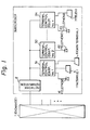
- a network termination unit is connected with a digital exchange through digital subscriber lines and a plurality of terminal control equipment units.
- the terminal control equipment units can in turn be connected to telephone sets, facsimile devices, data terminals, telex terminals, and so on.
- both a first incoming call and a second incoming call may be received at the same time.
- the terminal control equipment units With the arrival of the first incoming call, however, the terminal control equipment units enters into an alerting state.
- the terminal control equipment units send release signals because of the * busy * state for the second incoming call.
- the exchange receives a ringing signal when a first incoming call is received. It therefore processes other incoming calls as in a "busy" state even if some B channels are free. Thus, when two or more incoming calls arrive, connect processing is possible only for the first incoming call. This is disadvantageous from the viewpoints of serviceability as well as the utilization factor of the system.
- a switching system for a network having a plurality of terminal control equipment units connected to a network termination unit, in which terminal control equipment units of the same kind are connected with an exchange through a subscriber's line which has assigned to it a single subscriber number and which has a plurality of communication channels, the system including storage means for each terminal control equipment unit of the subscriber's line for storing call statuses of incoming calls.
- the storage means of the terminal control equipment units set respective call statuses for the first incoming call to a ringing state.
- the storage means When a second incoming call is received before a response to the first incoming call is transmitted, the storage means also set the call statuses for the second incoming call to a ringing state. When any one of the terminal control equipment units in the ringing state delivers a response, the call status for the first incoming call of the terminal control unit delivering the response is set to an active state and the call statuses for the first incoming call of the other terminal control units in the ringing state are released. The call statuses for the second incoming calls are maintained.
- a method for controlling the simultaneous arrival of a plurality of calls in a switching system having terminal control equipment units connected to an exchange termination through a digital subscriber's line.
- Each of the terminal control equipment units includes a first decision unit for deciding whether or not a terminal is free; a second decision unit for deciding whether or not an incoming call terminating state is in progress when the decision of the first decision unit is that a terminal is not in a free state; and an execution unit for executing processes corresponding to plural call terminations.
- the terminating control is carried out so that a ringing signal is sent back to the exchange when the decision of said first decision unit is that a terminal is not in a free state and the decision of said second decision unit is that an incoming call terminating state is in progress, and a connect signal by a terminal's answer is sent to the exchange by executing the process for the incoming call.
- Service facility information indicating the type of originating terminal, e.g., the telephone sets 41, 42 or the facsimile device 5, information indicating the number of the channel reserved as a communication channel, and other information are annexed to the signal All.
- the terminal control equipment units 31, 32 accommodating terminals corresponding to the service facility information send a ringing tone to the terminals and, at the same time, send back to the exchange 1 ringing signals A12, A13 showing that the terminals are in an ringing state.
- the terminal control equipment unit 32 sends a connect signal A14 to the exchange 1.
- the exchange.1 receives the connect signal A14, it sends a connect acknowledge signal A15 to the terminal control equipment unit 32.
- This enables the terminal accommodated in the terminal control equipment unit 32 to communicate with the originating terminal.
- the exchange 1 After the exchange 1 has sent that connect acknowledge signal A15 to the terminal control equipment unit 32, it sends a release signal A16 to the other terminal control equipment unit 31.
- the terminal control equipment unit 31 receives the release signal A16, it awaits the arrival of the following receipt request signal All or an originating operation by an accommodated terminal.
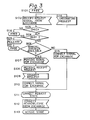
- FIG. 3 is a flow chart showing the operation of a conventional terminal control equipment unit at the time of an incoming signal.
- the steps S101, S116, S117, S108, Slll indicate stable states in call processing
- the steps A102, Sl14 indicate a request is made in call processing
- the steps S103, S104 indicate process branching.
- the terminal control equipment unit is in a free state, that is, a non- processing state, and receives a receipt request signal from the exchange (step S102), it checks the service facility information (step S103).
- the above-described check is called a compatibility check.
- the terminal control equipment unit When the result of the check is "NG", i.e., the terminal control equipment unit accommodates a different sort of terminal from the originating terminal, the terminal control equipment unit returns to the first free state (step S101).
- the result of the check is "OK”
- a check is made as to whether the terminal control equipment unit is busy or not (step S104). If busy, the terminal control equipment unit sends a release signal to the exchange (step S105) and returns to the first free state (step S117). If not busy, a check is made as to whether the terminal of the unit is a manual connect terminal, e.g., telephone set (step S106).
- the terminal control equipment unit sends a ringing signal to the exchange 1 (step S107), enters a state to receive a receipt request signal S108, and enters an ogerative state for sending a ringing tone, etc. (step S108).
- the terminal control equipment unit sends a connect signal to the exchange 1 (step S110).
- the terminal control equipment unit automatically sends a connect signal to the exchange 1 (step S115).
- step S110, S115 When the terminal control equipment unit sends a connect signal to the exchange 1 (step S110, S115), it enters a connect request state (step Slll). When it receives a connect acknowledge signal from the exchange 1 (step S112), it establishes a channel and enters an active state (step S113). Moreover, when a terminal sends an originating request signal (step Slll), the terminal control equipment unit performs originating call connect processing. This has nothing to do with the present invention, so a further explanation is omitted.
- FIG 4 is a flow chart showing the operation on the exchange side.
- the exchange receives an incoming call in the free state (step S201), it processes a network receipt request (step S202) and sends a receipt request signal to the terminal control equipment units through a network termination unit (step S203).
- the exchange then enters a call generating state (step S204).
- a terminal is a manual connect terminal
- the exchange receives a ringing signal (step S209) and proceeds to the step of call reception (step S210).
- the exchange receives a connect signal from the terminal control equipment unit (step S211), it enters a connect request state (step S206).
- the exchange When the terminal is an automatic connect terminal, the exchange does not receive a ringing signal, but directly receives a connect signal (step S205) to enter a connect request state (step S206). Then, it process a network connect acknowledge signal (step S207), forms a network path, and enters an active state (step S208).
- both a first and second incoming call may be received at the same time.
- the terminal control equipment units With the arrival of the first incoming call, the terminal control equipment units enter into an alerting state.
- the terminal control equipment units send release signals because of the "busy" state for the second incoming call.
- the exchange 1 sends a receipt request signal A21 resulting from the first incoming call to terminal control equipment units 31, 32.
- the terminal control equipment units 31, 32 send back ringing signals A22, A23.
- the exchange 1 sends a receipt request signal A24 resulting from a second incoming call before one of the terminal control equipment units 31, 32 send a connect signal, the terminal control equipment units 31, 32 send release signals A25, A26 indicating they are busy. Consequently, the exchange 1 sends a second call disconnect signal and sends a busy signal to the corresponding originating terminal for the second incoming call.
- the exchange receives a ringing signal for the first incoming call and processes other incoming calls as if busy notwithstanding the existence of free B channels.
- FIG. 6 is a block diagram of the main portion of a terminal control equipment unit in an embodiment of the present invention.
- 601 is a handset, 602 a sgeaker/microphone, 61 an analog circuit for processing a voice signal, 62 a codec, 63 a switch circuit, 64 a frame disassembler, 65 a receiver, 66 a frame detector, 67 a frame guard, 68 a data terminal, 69 a terminal interface, 70 a frame assembler, 71 a driver, 72 a keyboard, 73 a display unit for displaying transmitting and receiving data or the status of each portion, 74, 75, 77 input/output control units, 76 a D-channel transmission controller unit, 78 a central processing unit, 79 a main memory for storing programs, and a a control line.
- a time division multiplex line can be used for the subscriber's line for the terminal control equipment.
- Fig. 6 The construction shown in Fig. 6 is that of the case where two B channels and one D channel are provided.
- a receipt request signal from the exchange 1 (refer to Fig. 1) is received by the receiver 65
- frame synchronization is carried out by the frame detector 66.
- Disassembly of the two B channels and one D channel is performed by the frame disasembler 64.
- the D channel interacts with the central processing unit 78 through the transmission control unit 76.
- the receipt request signal from the exchange is transmitted by the D channel.
- the check on the service facility information and other information attached to the receipt request signal is performed under control of the central processing unit 78.
- the central processing unit 78 controls the switch circuit 63 according to the service facility information. When the terminating operation of a telephone is indicated, it connects the designated B channel with the codec 62.
- the ringing signal etc. may be formed by reading out patterns stored in the main memory 79, etc. under the control of the central processing unit 78.
- the ringing and other signals to be sent back to the exchange are formed and sent through the transmission control unit 76, multiplexed at the frame assembler 70, and sent from the driver 71 to a digital subscriber line.
- FIG. 7 is a flow chart of the main control of a terminal control equipment unit according to the present invention.
- the terminal control equipment unit receives a receipt request signal (step S302) from the exchange when in a free state (step S301) and performs the compatibility check (step S303).
- the terminal control equipment unit returns to the free state (step S301A).
- the check is "OK”
- a check is made whether or not the terminal control equipment unit is in a free state (step S304).
- step S304B When free, a check is made whether or not the accommodated terminals are a manual connect type (step S304B). If a manual connect type, the terminal control equipment unit sends a ringing signal to the exchange (step S307).
- step S304C If not a manual connect type, it sends a connect signal to the exchange (step S304C), shifts into the connect request state (step S325), and, upon receipt of a connect acknowledge signal (step S326), shifts into an active state (step S323).
- step S304A When not in a free state, a check is made whether or not the accommodated terminals are manual connect types (step S304A). When not manual, the terminal control equipment unit sends a release signal (step S306). When manual, it decides whether or not an incoming call is in progress (step S305). When not in progress, the terminal control equipment unit sends a release signal (step S306) as the "busy" state and returns to the free state. When in progress due to a previous receipt request signal, that is, when a first call has arrived, the terminal control equipment unit sends a ringing signal in the form of the termination of second incoming call (step S307).
- Decision means for deciding whether the free state exists and decision means for deciding whether an incoming call is in progress may be constructed by logic circuits. In Fig. 6, however, they are realized by programs stored in the main memory 79.
- the terminal control equipment unit awaits the arrival of a receipt request signal (step S308).
- a connect request is made by an off-hook operation, etc.
- the terminal control equipment determines if access rights have been secured, that is, if the process can run (step S310).
- the terminal control equipment unit operates under a multiprocessing (multitasking) system, so when two or more calls arrive simultaneously, a plurality of processes (tasks) are formed. Once access rights have been secured for one process, other processes cannot run until the previous access rights are released. In other words, when one process is being executed, the other processes must wait. This process for simultaneous arrival of two or more calls is realized by programs stored in the main memory 79.
- the terminal control equipment unit When access rights are secured, the terminal control equipment unit sends a connect signal (step S311) and enters a connect request state (step S312). When it receives a connect acknowledge signal from the exchange (step S313), the terminal control equipment unit releases the access rights (step S314) and enters an active state (step S323).
- step 5315 When the terminal control equipment unit is in the connect request state and receives a release request signal from the exchange (step 5315), for instance, when another terminal control equipment sends back a connect signal to the exchange as a terminal response first, the terminal control equipment unit transfers a connect signal send request to another process, as shown by the broken line (step S316), releases the access rights, i.e., process (step S317), and returns to the free state (step S301C).
- step S318 When the terminal control equipment unit cannot secure access rights, i.e., the process cannot run, it waits until the process can run (step S318).
- the terminal control equipment unit receives a connect signal send request (step S319), it sends out a connect signal (step S320) and enters a connect request state (step S321).
- the terminal control equipment unit receives a connect acknowledge signal from the exchange (step S322), the terminal control equipment unit enters an active state (step S323).
- FIG. 8 explains the sequence of an embodiment of the present invention.
- the figure shows the case when the check of the service facility and so on is "OK".
- the process PS1-1 and the process PSI-2 are processes at the terminal control equipment unit 31, while the process PS2-1 and the process PS2-2 are processes at the terminal control equipment unit 32.
- the exchange When a first call is received, the exchange sends a receipt request signal 1 to the terminal control equipment units 31, 32.
- the terminal control equipment unit 31, 32 then send ringing signals 1-1, 2-1 by means of the first processes PS1-1 and PS2-1, send a ringing tone to the terminals, and await a receipt request.
- the ringing tone can be issued through application of issuance instructions to the analog circuit 61 by the central processing unit 78, through a control line a and other lines.
- the exchange 1 transfers a receipt request signal 2 to the terminal control equipment units 31, 32 due to the arrival of a second call before a response to the first incoming call, which corresponds to the incoming call progress state in the flow chart of Fig. 7, the terminal control equipment units send ringing signals 2-1, 2-2 by the second processes PS1-2, PS2-2 and await a receipt request.
- the terminal control equipment unit 32 When the terminal control equipment unit 32 issues a connect answer signal due to an off-hook operation, etc., it stops the transmission of the ringing tone and decides whether a process can run.
- the terminal control equipment unit 32 secures access rights by the first process PS2-1, that is, the process can run, it sends a connect signal 2-1 and enters a connect request state by the first process PS2-1 and waits until the process can run by the second process PS2-2.
- the exchange 1 receives the connect signal 2-1, processes it as a connect signal 1 for the first call, and sends out a connect acknowledge signal 2-1.
- the terminal control equipment unit 32 When the terminal control equipment unit 32 receives the connect acknowledge signal, it releases the access right and enters an active state by the first process PS2-1.
- the exchange 1 sends a release signal 1-1 for the first incoming call to the terminal control equipment unit 31. On receiving the release signal, the terminal control equipment unit 31 returns to the free state by the first process PS1-1.
- a ringing tone is being issued to the terminals accommodated by the terminal control equipment unit 31.
- the terminal control equipment unit 31 sends a connect signal 1-2 by the second process PSI-2, suspends the ringing tone, and enters a connect request state.
- the exchange 1 receiving the connect signal 1-2 processes it as a connect signal 2 for the second incoming call, sends a connect acknowledge signal 1-2 to the terminal control equipment unit 31, and sends a release signal 2-2 to the terminal control equipment unit 32. Therefore, the terminal control equipment unit 31 enters an active state by the second process PS 1-2, while the terminal control equipment unit 32 returns to the free states by the second process PS 2-2.
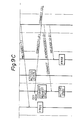
- Figure 9 explains the sequence of an embodiment of the present invention in case of a simultaneous response to a first incoming call.
- the terminal control equipment units 31, 32 When the terminal control equipment units 31, 32 are placed in a "receive receipt request" state by, first and second process as a result of a first incoming call and a second incoming call, if off-hook operations or other hook responses are made almost simultaneously, the terminal control equipment units 31, 32 enter connect request states by the first processes PS1-1, PS2-1 and wait until the processes can run by the second processes PS1-2, PS2-2.
- the exchange 1 processes a previously received connect signal, for instance, the connect signal 2-1, as the connect signal 1 for the first incoming call, sends a connect acknowledge signal 2-1 to the terminal control equipment unit 32, and sends a release signal 1-1 to the terminal control equipment unit 31.
- the terminal control equipment unit 31 since this corresponds to the state of receipt of a release request signal in the connect request state in the first process, sends a request for issuance of s response to the second process in the state of waiting until the process can run, and then transmits a connect signal 1-2 by the second process PS1-2.
- the exchange 1 process the connect signal 1-2 as a connect signal 2 for the second incoming call and transmits a connect acknowledge signal 1-2 to the terminal control equipment unit 31 and a release signal 2-2 to the terminal control equipment unit 32.
- the terminal control equipment unit 31 receives the connect acknowledge signal 1-2, it enters an active state by the second process PS1-2.
- the terminal control equipment unit 32 receives the release signal 2-2, it enters the free state by the second process PS2-2.
- the terminal control equipment unit 32 interacts with the first.incoming call, and the terminal control equipment unit 31 interacts with the second incoming call. Therefore, even if a plurality-of calls arrive simultaneously, connection control may be performed for answering terminals so long as there is a channel capable of communication.
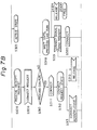
- Figure 10 explains control of simultaneous arrival of a plurality of calls and process control according to the present invention, etc. in conjunction with various data.
- the operating system is provided with running process information D209, including the number of the running process, and waiting process information D210i through D210n, including the number of the standby process, as common data.
- the system further controls the execution of process a, the management of process i to process n, the formation and elimination of. processes, etc. based upon the common data 208.
- Inter-call data may include on terminal speeds and other information 200 necessary for the compatibility check for terminals connected to the terminal control equipment units and status information 205 composed of, for instance, status number information D206 of a telephone terminal TELi and status number information D207 of a data terminal DTi for the terminals prescribed by the service facility classes for the management of call statuses.
- the inter-call data information 200 is illustrated in Fig. 10 as including telephone control information and data terminal control information for the case of connection of a telephone terminal and data terminal with the terminal control equipment unit.
- the status information 205 store status numbers for the telephone terminal and data terminal and enable discrimination of the state of the terminals.
- step S303 The compatibility check (step S303) performed after the receipt of the receipt request signal (step S302) described in Fig. 7 and the check as to manual answer (step S304A) described in Fig. 7 correspond to a decision by a call status control portion as to whether the service facility information 200 is matched.
- the null check (step S304) and the incoming call progress check (step S305) are made based on the status information D205.
Landscapes
- Engineering & Computer Science (AREA)
- Computer Networks & Wireless Communication (AREA)
- Theoretical Computer Science (AREA)
- Physics & Mathematics (AREA)
- General Engineering & Computer Science (AREA)
- General Physics & Mathematics (AREA)
- Sub-Exchange Stations And Push- Button Telephones (AREA)
- Data Exchanges In Wide-Area Networks (AREA)
- Exchange Systems With Centralized Control (AREA)
- Telephonic Communication Services (AREA)
Applications Claiming Priority (2)
| Application Number | Priority Date | Filing Date | Title |
|---|---|---|---|
| JP97571/84 | 1984-05-17 | ||
| JP59097571A JPS611153A (ja) | 1984-05-17 | 1984-05-17 | 複数コ−ル同時着信制御方法 |
Publications (3)
| Publication Number | Publication Date |
|---|---|
| EP0164611A2 true EP0164611A2 (de) | 1985-12-18 |
| EP0164611A3 EP0164611A3 (en) | 1986-01-02 |
| EP0164611B1 EP0164611B1 (de) | 1988-09-07 |
Family
ID=14195921
Family Applications (1)
| Application Number | Title | Priority Date | Filing Date |
|---|---|---|---|
| EP85106112A Expired EP0164611B1 (de) | 1984-05-17 | 1985-05-17 | Vermittlungssystem und Verfahren für ein Netzwerk mit einer Mehrzahl von Endgerätsteuereinheiten |
Country Status (7)
| Country | Link |
|---|---|
| US (1) | US4672662A (de) |
| EP (1) | EP0164611B1 (de) |
| JP (1) | JPS611153A (de) |
| KR (1) | KR900000723B1 (de) |
| CA (1) | CA1244537A (de) |
| DE (1) | DE3564898D1 (de) |
| SG (1) | SG42791G (de) |
Cited By (3)
| Publication number | Priority date | Publication date | Assignee | Title |
|---|---|---|---|---|
| EP0282158A3 (en) * | 1987-02-10 | 1989-06-07 | Canon Kabushiki Kaisha | Communication system |
| EP0371676A3 (de) * | 1988-11-30 | 1992-01-22 | AT&T Corp. | Änderung der Kommikationskanal-Zuweisung |
| EP0371674A3 (de) * | 1988-11-30 | 1992-01-22 | AT&T Corp. | Kommunikationskanalreservierung |
Families Citing this family (17)
| Publication number | Priority date | Publication date | Assignee | Title |
|---|---|---|---|---|
| JPH0685538B2 (ja) * | 1986-05-07 | 1994-10-26 | 日本電気株式会社 | 通信端末着信応答方式 |
| JPH01168155A (ja) * | 1987-12-24 | 1989-07-03 | Canon Inc | 通信端末装置 |
| US5297146A (en) * | 1988-07-01 | 1994-03-22 | Kabushiki Kaisha Toshiba | Communication terminal apparatus and its control method |
| US4998249A (en) * | 1988-10-28 | 1991-03-05 | Executone Information Systems, Inc. | Method and system for multiplexing telephone line circuits to highway lines |
| US5101427A (en) * | 1988-11-16 | 1992-03-31 | Canon Kabushiki Kaisha | Communication apparatus connected to ISDN |
| JP2585426B2 (ja) * | 1989-05-12 | 1997-02-26 | 株式会社日立製作所 | マルチ回線通信制御方法及びその装置 |
| US5276687A (en) * | 1989-04-14 | 1994-01-04 | Fujitsu Limited | Network system having different attributes of terminal equipment devices |
| EP0495128B1 (de) * | 1990-08-06 | 1996-03-06 | Fujitsu Limited | Übertragungsvorrichtung mit wiederholter schaltfunktion |
| US5214650A (en) * | 1990-11-19 | 1993-05-25 | Ag Communication Systems Corporation | Simultaneous voice and data system using the existing two-wire inter-face |
| JP2832096B2 (ja) * | 1991-06-10 | 1998-12-02 | キヤノン株式会社 | 通信制御装置 |
| JP3411300B2 (ja) * | 1992-02-18 | 2003-05-26 | 株式会社日立製作所 | 情報処理装置 |
| US5307347A (en) * | 1992-04-10 | 1994-04-26 | International Business Machines Corporation | Method and apparatus for sharing a telecommunications channel among multiple users |
| KR960014305B1 (ko) * | 1992-04-15 | 1996-10-15 | 마쯔시다멘기산교 가부시기가이샤 | 팩시밀리장치 |
| US5953350A (en) * | 1995-03-13 | 1999-09-14 | Selsius Systems, Inc. | Multimedia client for multimedia/hybrid network |
| US5734828A (en) * | 1995-08-30 | 1998-03-31 | Intel Corporation | System for accessing/delivering on-line/information services via individualized environments using streamlined application sharing host and client services |
| JP2798019B2 (ja) * | 1995-09-25 | 1998-09-17 | 日本電気株式会社 | 蓄積型データ通信端末 |
| US5937057A (en) * | 1997-03-05 | 1999-08-10 | Selsius Systems, Inc. | Video/audio communications call center and method of operation thereof |
Family Cites Families (2)
| Publication number | Priority date | Publication date | Assignee | Title |
|---|---|---|---|---|
| US4394756A (en) * | 1980-09-12 | 1983-07-19 | Bell Telephone Laboratories, Incorporated | Generation of busy signals in a digital concentrator |
| JPS58151197A (ja) * | 1982-03-04 | 1983-09-08 | Nippon Telegr & Teleph Corp <Ntt> | 高機能端末における通信チヤネルアクセス方式 |
-
1984
- 1984-05-17 JP JP59097571A patent/JPS611153A/ja active Granted
-
1985
- 1985-05-15 US US06/734,110 patent/US4672662A/en not_active Expired - Lifetime
- 1985-05-16 KR KR1019850003365A patent/KR900000723B1/ko not_active Expired
- 1985-05-16 CA CA000481709A patent/CA1244537A/en not_active Expired
- 1985-05-17 EP EP85106112A patent/EP0164611B1/de not_active Expired
- 1985-05-17 DE DE8585106112T patent/DE3564898D1/de not_active Expired
-
1991
- 1991-06-08 SG SG42791A patent/SG42791G/en unknown
Non-Patent Citations (1)
| Title |
|---|
| None |
Cited By (6)
| Publication number | Priority date | Publication date | Assignee | Title |
|---|---|---|---|---|
| EP0282158A3 (en) * | 1987-02-10 | 1989-06-07 | Canon Kabushiki Kaisha | Communication system |
| US5583930A (en) * | 1987-02-10 | 1996-12-10 | Canon Kabushiki Kaisha | Communication apparatus for responding to calls to a different apparatus on a network |
| US5648971A (en) * | 1987-02-10 | 1997-07-15 | Canon Kabushiki Kaisha | Communication apparatus providing improved information on the states of data channels |
| EP0500194B1 (de) * | 1987-02-10 | 1998-05-27 | Canon Kabushiki Kaisha | Kommunikationsgerät |
| EP0371676A3 (de) * | 1988-11-30 | 1992-01-22 | AT&T Corp. | Änderung der Kommikationskanal-Zuweisung |
| EP0371674A3 (de) * | 1988-11-30 | 1992-01-22 | AT&T Corp. | Kommunikationskanalreservierung |
Also Published As
| Publication number | Publication date |
|---|---|
| EP0164611B1 (de) | 1988-09-07 |
| DE3564898D1 (en) | 1988-10-13 |
| EP0164611A3 (en) | 1986-01-02 |
| CA1244537A (en) | 1988-11-08 |
| KR900000723B1 (ko) | 1990-02-07 |
| JPS611153A (ja) | 1986-01-07 |
| US4672662A (en) | 1987-06-09 |
| JPH0329346B2 (de) | 1991-04-23 |
| SG42791G (en) | 1993-02-19 |
| KR850008016A (ko) | 1985-12-11 |
Similar Documents
| Publication | Publication Date | Title |
|---|---|---|
| US4672662A (en) | Switching system and method for network having a plurality of terminal control equipment units | |
| JP2537478B2 (ja) | 会議電話装置 | |
| US4635251A (en) | Meet-me conference with control capabilities | |
| CA1331802C (en) | Modularly structured digital communications system having operations-oriented and security-oriented components | |
| CA1207875A (en) | Communications switching system | |
| GB2049356A (en) | Integrated automatic call destribution facility and pbx system | |
| EP0684722B1 (de) | Umlenkschnittstelle zwischen zwei Fernsprechleitungen und einer Fernsprechstelle | |
| JP2794349B2 (ja) | 着信制御方式 | |
| JP3496802B2 (ja) | 呼接続方法 | |
| JPS5923693A (ja) | インテリジエント通信方式 | |
| JPH0366869B2 (de) | ||
| JPH04291860A (ja) | 通信システムの予約管理方式 | |
| JP3455095B2 (ja) | Isdnビル電話システムへの受付台端末の収容方法 | |
| JPH0124461B2 (de) | ||
| JPS6179398A (ja) | 加入者呼出方式 | |
| JPH0834526B2 (ja) | 通信端末装置 | |
| JPS62230251A (ja) | 共通線信号処理方式 | |
| JPS61129954A (ja) | コールウェイティング機能を備える自動交換機システム | |
| JPH01164154A (ja) | デイジタル電話装置 | |
| JPS6150440A (ja) | タ−ミナルアダプタ | |
| CN85103684B (zh) | 交换系统中呼叫同时到达的控制方法和装置 | |
| JPS63157553A (ja) | 統合メ−ル装置接続方式 | |
| JPS6126356A (ja) | デジタル端末収容方式 | |
| JPH0267036A (ja) | 通信方式 | |
| JPH036994A (ja) | バス型小規模通信システム |
Legal Events
| Date | Code | Title | Description |
|---|---|---|---|
| PUAI | Public reference made under article 153(3) epc to a published international application that has entered the european phase |
Free format text: ORIGINAL CODE: 0009012 |
|
| PUAL | Search report despatched |
Free format text: ORIGINAL CODE: 0009013 |
|
| AK | Designated contracting states |
Kind code of ref document: A2 Designated state(s): DE FR GB |
|
| AK | Designated contracting states |
Kind code of ref document: A3 Designated state(s): DE FR GB |
|
| 17P | Request for examination filed |
Effective date: 19860219 |
|
| 17Q | First examination report despatched |
Effective date: 19870226 |
|
| GRAA | (expected) grant |
Free format text: ORIGINAL CODE: 0009210 |
|
| AK | Designated contracting states |
Kind code of ref document: B1 Designated state(s): DE FR GB |
|
| REF | Corresponds to: |
Ref document number: 3564898 Country of ref document: DE Date of ref document: 19881013 |
|
| ET | Fr: translation filed | ||
| RIN2 | Information on inventor provided after grant (corrected) |
Free format text: NISHINO, TETSUO * OKAMURA, HIROKO * YAMATANI, YASUNORI |
|
| PLBI | Opposition filed |
Free format text: ORIGINAL CODE: 0009260 |
|
| 26 | Opposition filed |
Opponent name: SIEMENS AKTIENGESELLSCHAFT, BERLIN UND MUENCHEN Effective date: 19890606 |
|
| PLBN | Opposition rejected |
Free format text: ORIGINAL CODE: 0009273 |
|
| STAA | Information on the status of an ep patent application or granted ep patent |
Free format text: STATUS: OPPOSITION REJECTED |
|
| 27O | Opposition rejected |
Effective date: 19930427 |
|
| PGFP | Annual fee paid to national office [announced via postgrant information from national office to epo] |
Ref country code: FR Payment date: 20000510 Year of fee payment: 16 |
|
| PGFP | Annual fee paid to national office [announced via postgrant information from national office to epo] |
Ref country code: DE Payment date: 20000515 Year of fee payment: 16 |
|
| PGFP | Annual fee paid to national office [announced via postgrant information from national office to epo] |
Ref country code: GB Payment date: 20000517 Year of fee payment: 16 |
|
| PG25 | Lapsed in a contracting state [announced via postgrant information from national office to epo] |
Ref country code: GB Free format text: LAPSE BECAUSE OF NON-PAYMENT OF DUE FEES Effective date: 20010517 |
|
| GBPC | Gb: european patent ceased through non-payment of renewal fee |
Effective date: 20010517 |
|
| PG25 | Lapsed in a contracting state [announced via postgrant information from national office to epo] |
Ref country code: FR Free format text: LAPSE BECAUSE OF NON-PAYMENT OF DUE FEES Effective date: 20020131 |
|
| PG25 | Lapsed in a contracting state [announced via postgrant information from national office to epo] |
Ref country code: DE Free format text: LAPSE BECAUSE OF NON-PAYMENT OF DUE FEES Effective date: 20020301 |
|
| APAH | Appeal reference modified |
Free format text: ORIGINAL CODE: EPIDOSCREFNO |