EP0164729A2 - Motorsteuerungssystem - Google Patents
Motorsteuerungssystem Download PDFInfo
- Publication number
- EP0164729A2 EP0164729A2 EP85107195A EP85107195A EP0164729A2 EP 0164729 A2 EP0164729 A2 EP 0164729A2 EP 85107195 A EP85107195 A EP 85107195A EP 85107195 A EP85107195 A EP 85107195A EP 0164729 A2 EP0164729 A2 EP 0164729A2
- Authority
- EP
- European Patent Office
- Prior art keywords
- engine
- signal
- intake passage
- airflow
- temperature
- Prior art date
- Legal status (The legal status is an assumption and is not a legal conclusion. Google has not performed a legal analysis and makes no representation as to the accuracy of the status listed.)
- Granted
Links
Images


Classifications
-
- F—MECHANICAL ENGINEERING; LIGHTING; HEATING; WEAPONS; BLASTING
- F02—COMBUSTION ENGINES; HOT-GAS OR COMBUSTION-PRODUCT ENGINE PLANTS
- F02D—CONTROLLING COMBUSTION ENGINES
- F02D41/00—Electrical control of supply of combustible mixture or its constituents
- F02D41/02—Circuit arrangements for generating control signals
- F02D41/18—Circuit arrangements for generating control signals by measuring intake air flow
- F02D41/187—Circuit arrangements for generating control signals by measuring intake air flow using a hot wire flow sensor
-
- F—MECHANICAL ENGINEERING; LIGHTING; HEATING; WEAPONS; BLASTING
- F02—COMBUSTION ENGINES; HOT-GAS OR COMBUSTION-PRODUCT ENGINE PLANTS
- F02D—CONTROLLING COMBUSTION ENGINES
- F02D41/00—Electrical control of supply of combustible mixture or its constituents
- F02D41/24—Electrical control of supply of combustible mixture or its constituents characterised by the use of digital means
- F02D41/26—Electrical control of supply of combustible mixture or its constituents characterised by the use of digital means using computer, e.g. microprocessor
- F02D41/263—Electrical control of supply of combustible mixture or its constituents characterised by the use of digital means using computer, e.g. microprocessor the program execution being modifiable by physical parameters
Definitions
- the present invention relates to a control system for an engine, and more specifically to an electronic control system using a microcomputer in which means for measuring the quantity of intake air supplied to the engine is improved so that a digitally represented measurement output can be provided for effective use, and that the measurement of the intake air quantity can accurately be executed for high-accuracy injection quantity control for the engine even under a high engine load condition.
- Monitoring means for the engine condition include means for measuring the quantity of intake air.
- an airflow measuring device of a heat-wire type which is set in an intake passage of the engine.
- This measuring device is constructed so that a temperature sensing element, which is adapted to generate heat when supplied with a heating current, is disposed in the intake passage.
- the quantity of air passing through the intake passage is measured by determining the temperature change of the temperature sensing element.
- the temperature sensing element is formed of a resistance element which has a temperature characteristic such that resistance depends on temperature. Thus, the temperature of the temperature sensing element can be measured by determining its resistance. Since the temperature sensing element is disposed in the intake passage, the amount of heat radiated from the temperature sensing element varies with the quantity of intake airflow. Therefore, if the heating current, for example, is controlled so that the temperature sensing element is kept at a fixed temperature, the level of the heating current is proportional to the intake airflow quantity. Thus, the intake airflow quantity may be detected from the value of the heating current.
- a microcomputer For electronically calculating the injection quantity for the engine to execute fuel injection control on the basis of a measurement signal indicative of the intake air quantity, a microcomputer is used as an arithmetic control means therefor.
- the measurement signal from the airflow measuring device is converted into digital data before it is supplied to the microcomputer.
- the airflow measurement signal is analog data such as a current value
- the engine control system requires an A/D converter with very high accuracy, complicating its construction.
- An object of the present invention is to provide a control system for an engine so constructed that an intake airflow measurement signal for the engine is digitally expressed for effective use in a microcomputer if a control unit of the engine is formed of an electronic apparatus using the microcomputer, and that the engine control unit is fully simplified in construction to permit simple calculation of injection quantity.
- Another object of the invention is to provide a control system for an engine in which the quantity of intake airflow can accurately be measured especially when the engine is operated in a high load condition, thus ensuring high-accuracy intake airflow measurement for high-accuracy operation control under any operating condition.
- a temperature sensing element as a heat generating element having a temperature-resistance characteristic such that its resistance is established in response to its temperature is disposed in an intake passage of the engine.
- the temperature sensing element is supplied with a heating current in response to a start pulse signal which is generated with every two periods for each engine combustion cycle.
- the heating current supply is interrupted, and a pulse signal indicative of a time duration equivalent to the period of time during which the heating current is supplied to the temperature sensing element is delivered as an airflow measurement signal.
- a correction value for the airflow measurement signals is calculated from the average of and the difference between the two measurement signals.
- the measurement signals are operated to correct the airflow data in accordance with the correction value. Based on the corrected airflow data, calculation of the injection quantity and the like is executed.
- the quantity of air passing through the intake passage is represented by a time period, so that it can be handled as a digital measurement output signal by measuring the time period by clock signal counting.
- the measurement signal can directly be used without requiring A/D conversion, greatly facilitating simplification of the control system in construction.
- accurate intake airflow measurement can be executed without fail even if the intake air for the engine is subject to pulsation caused by engine rotation, and especially if a high engine load condition makes components of the pulsation so great that there are backflow components responsive to the pulsation. Namely, the measurement is executed twice for each combustion cycle of the engine, and a correction value is set corresponding to two measurement results so that the airflow measurement signal is corrected in accordance with the correction value.
- the engine can be electronically controlled with high accuracy under any operating conditions.
- Intake air for the engine 11 is introduced through an air filter 12 and distributed to a plurality of cylinders of the engine 11 through an intake passage 13.
- the intake passage 13 is provided with a throttle valve 15 which is driven by an accelerator pedal 14.
- a temperature sensing element 17 constituting an airflow measuring device 16 of a heat-wire type is set in the intake passage 13.
- the temperature sensing element 17, which generates heat when supplied with electric power, is formed of a heater, such as a platinum wire, which has such a temperature-resistance characteristic that its resistance depends on its temperature.
- a measurement output signal delivered from the airflow measuring device 16 is supplied to an engine control unit 18 whi.ch is formed of a microcomputer.
- the temperature sensing element 17 is controlled for its generation of heat in accordance with an instruction from the control unit 18.
- the engine control unit 18 is further supplied, as detection signals for the operating conditions of the engine 11, with output signals from a rotational speed detector 19 for detecting the rotating conditions of the engine 11, an engine cooling water temperature detector (not shown), and an exhaust gas temperature detector (not shown), an air-fuel ratio detection signal, etc.
- the rotational speed detector 19 delivers signals responsive to crank angular positions, 60 degrees and 150 degrees, of the cylinders of the engine 11.
- the control unit 18 calculates an injection quantity compatible with the current operating conditions of the engine 11, and supplies injection period signals responsive to the injection quantity to injectors 201, 202, 203 and 204 which are provided corresponding to the individual cylinders of the engine 11.
- signals for the injection quantity are pulse signals indicative of time durations, which are supplied to the injectors 201 to 204 through resistors 211, 212, 213 and 214 for protection, respectively.
- the injection quantity is determined in response to the valve-open periods of the injectors 201 to 204.
- the injectors 201 to 204 are supplied through a distributor 24 with fuel which is delivered from a fuel tank 23 by a fuel pump 22.
- the pressure of the fuel fed to the distributor 24 is kept constant by a pressure regulator 25, so that the injection quantity can accurately be set in accordance with the valve-open periods of the injectors 201 to 204.
- the engine control unit 18 also gives an instruction to an igniter 26 so that ignition signals are supplied through a distributor 27 to ignition coils 281, 282, 283 and 284 which are provided corresponding to the engine cylinders.
- Fig. 2 shows the temperature sensing element 17 constituting the airflow measuring device 16, in which a resistance wire 172 with a temperature resistance characteristic is wound around a ceramic bobbin 171.
- Shafts 173 and 174 formed of a good conductor protrude individually from both end portions of the bobbin 171.
- the shafts 173 and 174 are supported by pins 175 and 176, respectively.
- heating current is supplied to the resistance wire 172 through the pins 175 and 176.
- Fig. 3 shows a modified example of the temperature sensing element 17, in which the resistance wire 172 is formed by printed wiring on an insulator film 177.
- the film 177 is supported on a substrate 178 formed of an insulator.
- Wires 179a and 179b connected to the resistance wire 172 are formed on the surface of the substrate 178.
- Fig. 4 shows a circuit arrangement of the airflow measuring device 16 used in the aforesaid manner.
- an auxiliary temperature sensing element 30, as well as the temperature sensing element 17, is set inside the intake passage 13.
- the auxiliary temperature sensing element 30 is constructed in the same manner as the temperature sensing element 17.
- the auxiliary temperature sensing element 30, whose resistance value is set in accordance with the temperature of air passing through the intake passage 13, serves as an air temperature measuring element.
- Nodes a and b as output terminals of the bridge circuit are connected to a comparator 33.
- the comparator 33 delivers an output signal when the temperature of the temperature sensing member 17 rises to a level such that there is a specified difference between it and the air temperature measured by the auxiliary temperature sensing element 30.
- the output signal from the comparator 33 serves for reset control of a flip-flop circuit 34.
- the flip-flop circuit 34 is set by a start pulse signal which is supplied from the engine control unit 18.
- the start pulse signal is a signal which is synchronized with the rotation of the engine 11.
- An output signal from the flip-flop circuit 34 which goes high when the flip-flop circuit 34 is set, is delivered as an output signal with a set pulse duration through a buffer amplifier 35, and serves to control the base of a transistor 36 for intermittent, pulsative control of electric current supplied to the bridge circuit including the temperature sensing element 17.
- a reference voltage source 37 and a differential amplifier 38 constitute a reference voltage setting circuit, which regulates the voltage of heating current supplied to the bridge circuit.
- the flip-flop circuit 34 is set by the start pulse signal, so that the output signal from the circuit 34 rises, as shown in Fig. 5B.
- the transistor 36 is turned on to allow the heating current to be supplied to the temperature sensing element 17, thereby causing the temperature of the temperature sensing element 17 to rise as shown in Fig. 5C.
- the air flowing through the intake passage 13 functions as a heat radiating element for the temperature sensing element 17.
- the speed of the temperature rise in the temperature sensing element 17 is responsive to the quantity of airflow in the intake passage 13. More specifically, the temperature. rise speed of the temperature sensing element 17 is low when the airflow quantity is large, and the former increases as the latter decreases. Accordingly, the period of time when the flip-flop circuit 34 is set is proportional to the flow quantity of intake air, and the output pulse signal (Fig. 5B) from the flip-flop circuit 34 serves as a measurement output signal whose pulse width is indicative of a measured value.
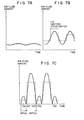
- Figs. 6A and 6B show different states of intake airflow in the intake passage 13 obtained under low and medium load conditions of the engine 11, respectively.
- full lines represent the airflow rate varying with every ignition cycle or combustion cycle, while chain lines indicate display modes of the detected airflow rate.
- the start pulse signal is generated with every one-half period of each combustion cycle of each cylinder. More specifically, in the case of the four-cycle, four-cylinder engine, the start pulse signal is generated with every engine crank cycle of 90 degrees CA.
- broken lines represent display modes of the measurement output signal obtained in response to the start pulse signal, varying with pulsation of airflow in the intake passage 13.
- Figs. 7A, 7B and 7C correspond to low, medium and high load conditions, respectively.
- injection quantity, ignition timing and the like are calculated with the use of airflow quantity per revolution "G/N" which is calculated on the basis of the aforesaid airflow measurement signal.
- Fig. 8 is a flow chart showing a sequence of processes for extracting an airflow rate signal "G/N" used in the control unit 18.
- interrupt processing for calculating the airflow quantity is executed for each 90 degrees CA of the engine 11, i.e., at crankshaft positions 60° and 150° as shown in Fig. 7C.
- step 101 the pulse duration T of the output pulse signal from the measuring device 16 is measured and read by a high-speed input counter.
- step 102 the period during which the duration T is read is checked for correspondence to any ignition cycle of the engine 11.
- step 103 an airflow rate (G/N)i for the detected cycle is calculated from the measured duration T.
- step 104 G/N is calculated as it is.
- the duration T as compared with quantity of air G and engine speed (number of revolutions) N may be expressed as follows:
- step 105 the data (G/N)i obtained in step 104 is added to (G/N)i-l for the preceding detected cycle to obtain an average airflow rate data signal (G/N)m.
- the data (G/N)i-1 used here is the G/N stored in the memory in step 104.
- step 106 the (G/N)i-l is subtracted from the (G/N)i to find the remainder or the difference ⁇ (G/N).
- step 107 a correction factor K is calculated from the previously calculated ⁇ (G/N) and (G/N)m.
- Fig. 9 shows an experimental relationship between the correction factor K and ⁇ (G/N)/(G/N)m.
- the correction factor K can readily be obtained from a stored map or the like.
- the ⁇ (G/N)/(G/N)m is obtained on the basis of Figs. 8 and 9 for the purpose of discrimination of the load condition of the engine 11. The higher the engine load, the greater the ⁇ (G/N) and hence the greater the ⁇ (G/N)/(G/N)m will be.
- an airflow data signal (G/N)p to be used in injection quantity calculation control for each ignition cycle or combustion cycle is calculated in step 108.
- the interrupt processing for airflow calculation is ends.
- Fig. 10 is a flow chart showing the flow of interrupt processing for the calculation of injection quantity in the engine control unit 18. The interruption is executed at every 360 degrees CA of the engine 11.
- a fundamental injection pulse width Tp is calculated on the basis of the airflow data (G/N)p.
- a final injection pulse width Tinj is calculated in step 202.
- a correction factor K B calculated in response to the engine cooling water temperature detection signal, air-fuel ratio detection signal and the like and an add correction term T V are used.
- a valve-opening instruction is given to each injector to start fuel injection, and an output counter is set to an injection end time responsive to the injection pulse width Tinj.
- the fuel injection control executed in a manner such that the injection of each injector ends when time counting of the output counter finishes.
- Fig. 11 is a flow chart showing the flow of interrupt processing for ignition timing in the engine control unit 18.
- a fundamental ignition timing (6i)p is calculated from the (G/N)p.
- the value of the fundamental ignition timing (0i)p is experimentally obtained from the relationship between, for example, (G/N)p and engine speed N. The value obtained in this manner may be read from, e.g., a two-dimensional map.
- the correction operation is executed, in step 302, on the basis of a correction value obtained in accordance with the detection signals for the operating conditions of the engine 11 are the same as used in the injection quantity calculation.
- a final injection timing is calculated.
- the final ignition timing is set in the output counter.
- the intake airflow measuring operation is described as being executed with every one-half combustion cycle or 90 degrees CA interval.
- the combustion cycle may be divided by 60 egrees CA interval and 120 degrees CA interval so that the airflow measurement is executed at two points corresponding to the points of division.
Landscapes
- Engineering & Computer Science (AREA)
- Chemical & Material Sciences (AREA)
- Combustion & Propulsion (AREA)
- Mechanical Engineering (AREA)
- General Engineering & Computer Science (AREA)
- Computer Hardware Design (AREA)
- Microelectronics & Electronic Packaging (AREA)
- Electrical Control Of Air Or Fuel Supplied To Internal-Combustion Engine (AREA)
- Combined Controls Of Internal Combustion Engines (AREA)
Applications Claiming Priority (2)
| Application Number | Priority Date | Filing Date | Title |
|---|---|---|---|
| JP121519/84 | 1984-06-13 | ||
| JP59121519A JPS611847A (ja) | 1984-06-13 | 1984-06-13 | 内燃機関の制御装置 |
Publications (3)
| Publication Number | Publication Date |
|---|---|
| EP0164729A2 true EP0164729A2 (de) | 1985-12-18 |
| EP0164729A3 EP0164729A3 (en) | 1986-03-26 |
| EP0164729B1 EP0164729B1 (de) | 1988-09-21 |
Family
ID=14813225
Family Applications (1)
| Application Number | Title | Priority Date | Filing Date |
|---|---|---|---|
| EP85107195A Expired EP0164729B1 (de) | 1984-06-13 | 1985-06-11 | Motorsteuerungssystem |
Country Status (4)
| Country | Link |
|---|---|
| US (1) | US4736302A (de) |
| EP (1) | EP0164729B1 (de) |
| JP (1) | JPS611847A (de) |
| DE (1) | DE3565152D1 (de) |
Cited By (1)
| Publication number | Priority date | Publication date | Assignee | Title |
|---|---|---|---|---|
| GB2294767A (en) * | 1994-10-05 | 1996-05-08 | Univ Robert Gordon | Hot-wire flow rate measurement |
Families Citing this family (11)
| Publication number | Priority date | Publication date | Assignee | Title |
|---|---|---|---|---|
| US4860222A (en) * | 1988-01-25 | 1989-08-22 | General Motors Corporation | Method and apparatus for measuring engine mass air flow |
| JP2717665B2 (ja) * | 1988-05-31 | 1998-02-18 | 株式会社豊田中央研究所 | 内燃機関の燃焼予測判別装置 |
| DE4004552C2 (de) * | 1989-02-14 | 1994-07-07 | Mitsubishi Electric Corp | Signalverarbeitungsverfahren für einen thermischen Durchflußsensor |
| JP3135245B2 (ja) * | 1990-03-19 | 2001-02-13 | 株式会社日立製作所 | パルス出力型熱線式空気流量計 |
| JP2637631B2 (ja) * | 1991-03-25 | 1997-08-06 | 株式会社クボタ | 穀粒貯留装置 |
| JP3133608B2 (ja) * | 1994-02-28 | 2001-02-13 | 株式会社ユニシアジェックス | 熱式空気流量検出装置 |
| US5804712A (en) * | 1996-09-27 | 1998-09-08 | Brunswick Corporation | Oil flow sensor |
| US7398681B2 (en) * | 2005-09-22 | 2008-07-15 | The Regents Of The University Of California | Gas sensor based on dynamic thermal conductivity and molecular velocity |
| DE102008000916B4 (de) * | 2007-04-02 | 2021-12-16 | Denso Corporation | Verbrennungssteuerungsvorrichtung für direkt einspritzende Kompressionszündungskraftmaschine |
| CN110714845B (zh) * | 2018-07-13 | 2022-05-03 | 丰田自动车株式会社 | 发动机控制装置及发动机控制方法以及记录介质 |
| JP7268533B2 (ja) * | 2019-08-23 | 2023-05-08 | トヨタ自動車株式会社 | エンジン制御装置 |
Family Cites Families (20)
| Publication number | Priority date | Publication date | Assignee | Title |
|---|---|---|---|---|
| DE1109953B (de) * | 1957-05-02 | 1961-06-29 | Bosch Gmbh Robert | Elektrisch gesteuerte Kraftstoff-Einspritzanlage fuer Brennkraftmaschinen |
| US3803913A (en) * | 1970-07-06 | 1974-04-16 | J Tracer | Apparatus for determining heat-transfer rates and thus the flow rates or thermal conductivities of fluids |
| US3928800A (en) * | 1973-06-25 | 1975-12-23 | Sperry Rand Corp | Calorimetric resistance bridges |
| DE2448304C2 (de) * | 1974-10-10 | 1986-04-03 | Robert Bosch Gmbh, 7000 Stuttgart | Elektrisch gesteuerte Kraftstoffeinspritzanlage für Brennkraftmaschinen |
| DE2840793C3 (de) * | 1978-09-20 | 1995-08-03 | Bosch Gmbh Robert | Verfahren und Einrichtung zum Bestimmen der von einer Brennkraftmaschine angesaugten Luftmenge |
| DE2845661A1 (de) * | 1978-10-20 | 1980-05-08 | Bosch Gmbh Robert | Vorrichtung zur messung der masse eines stroemenden mediums |
| US4304129A (en) * | 1978-11-13 | 1981-12-08 | Nippon Soken, Inc. | Gas flow measuring apparatus |
| JPS55104538A (en) * | 1979-02-05 | 1980-08-11 | Hitachi Ltd | Air-fuel ratio controlling system for internal combustion engine |
| JPS5624521A (en) * | 1979-08-07 | 1981-03-09 | Japan Electronic Control Syst Co Ltd | Method and device for converting function for hot-wire type flowmeter |
| US4357830A (en) * | 1979-09-21 | 1982-11-09 | Nippon Soken, Inc. | Gas flow measuring apparatus |
| US4334186A (en) * | 1979-10-03 | 1982-06-08 | Hitachi, Ltd. | Apparatus for driving hot-wire type flow sensor |
| JPS5692330A (en) * | 1979-12-25 | 1981-07-27 | Hitachi Ltd | Signal processing method for hot wire flow sensor |
| JPS56108909A (en) * | 1980-01-31 | 1981-08-28 | Hitachi Ltd | Air flow rate detector |
| US4424568A (en) * | 1980-01-31 | 1984-01-03 | Hitachi, Ltd. | Method of controlling internal combustion engine |
| JPS56143915A (en) * | 1980-04-11 | 1981-11-10 | Nippon Soken Inc | Measuring device for gas flow rate |
| EP0070801A1 (de) * | 1981-07-13 | 1983-01-26 | Battelle Memorial Institute | Verfahren und Vorrichtung zur Bestimmung mindestens eines momentanen Parameters eines Fluids, der mit einem Wärmeaustausch einer in das Fluid eintauchenden Sonde korreliert ist |
| DE3218931A1 (de) * | 1982-05-19 | 1983-11-24 | Bosch Gmbh Robert | Verfahren zur messung der von einer brennkraftmaschine angesaugten pulsierenden luftmasse |
| DE3248603A1 (de) * | 1982-12-30 | 1984-07-12 | Robert Bosch Gmbh, 7000 Stuttgart | Einrichtung zur messung des massendurchsatzes eines stroemenden mediums |
| EP0144027B1 (de) * | 1983-11-16 | 1990-06-20 | Nippondenso Co., Ltd. | Gerät zum Messen der Ansaugluftdurchflussquote für einen Motor |
| JPS60216047A (ja) * | 1984-04-11 | 1985-10-29 | Nippon Denso Co Ltd | 内燃機関の制御装置 |
-
1984
- 1984-06-13 JP JP59121519A patent/JPS611847A/ja active Granted
-
1985
- 1985-06-07 US US06/742,524 patent/US4736302A/en not_active Expired - Fee Related
- 1985-06-11 DE DE8585107195T patent/DE3565152D1/de not_active Expired
- 1985-06-11 EP EP85107195A patent/EP0164729B1/de not_active Expired
Cited By (1)
| Publication number | Priority date | Publication date | Assignee | Title |
|---|---|---|---|---|
| GB2294767A (en) * | 1994-10-05 | 1996-05-08 | Univ Robert Gordon | Hot-wire flow rate measurement |
Also Published As
| Publication number | Publication date |
|---|---|
| JPS611847A (ja) | 1986-01-07 |
| EP0164729B1 (de) | 1988-09-21 |
| EP0164729A3 (en) | 1986-03-26 |
| JPH0578668B2 (de) | 1993-10-29 |
| DE3565152D1 (en) | 1988-10-27 |
| US4736302A (en) | 1988-04-05 |
Similar Documents
| Publication | Publication Date | Title |
|---|---|---|
| US4736302A (en) | Control system for determining the quantity of intake air of an internal combustion engine | |
| US4565091A (en) | Apparatus for measuring the quantity of airflow passing through an intake passage of an engine | |
| JPS6112114B2 (de) | ||
| US4517948A (en) | Method and apparatus for controlling air-fuel ratio in internal combustion engines | |
| US4730255A (en) | Engine control apparatus | |
| US4991554A (en) | Device for controlling ignition timing of engine | |
| US4671242A (en) | Engine control apparatus | |
| US4454845A (en) | Data sampling system for electronic engine controllers | |
| US4633838A (en) | Method and system for controlling internal-combustion engine | |
| EP0064664B1 (de) | Elektronische Steuervorrichtung für Brennkraftmaschinen | |
| JP2654706B2 (ja) | 熱式吸入空気量センサ | |
| EP0280878B1 (de) | Vorrichtung zur Bestimmung der Drehzahl eines Verbrennungsmotors | |
| JP2524847B2 (ja) | 熱式吸入空気量センサ | |
| GB2220085A (en) | Ic engine testing | |
| EP0180130B1 (de) | Steuervorrichtung für einen Motor mit Ansaugrohr | |
| US5467752A (en) | Method and apparatus for controlling the fuel injection/ignition timing of internal combustion engines, and a crank angle sensor using same | |
| JPS61265334A (ja) | 内燃機関の空燃比制御方法 | |
| JPH0548402B2 (de) | ||
| JP2502570B2 (ja) | エンジン制御装置 | |
| JPH0581744B2 (de) | ||
| JPS60247029A (ja) | エンジンの制御装置 | |
| KR830001632B1 (ko) | 열선식 유속계측 장치 | |
| JPS60187817A (ja) | 内燃機関の制御に用いられる空気流量検出装置 | |
| JPS6390640A (ja) | 内燃機関用燃料供給量制御装置 | |
| JPS60187816A (ja) | 空気流量検出装置 |
Legal Events
| Date | Code | Title | Description |
|---|---|---|---|
| PUAI | Public reference made under article 153(3) epc to a published international application that has entered the european phase |
Free format text: ORIGINAL CODE: 0009012 |
|
| AK | Designated contracting states |
Designated state(s): DE FR GB |
|
| PUAL | Search report despatched |
Free format text: ORIGINAL CODE: 0009013 |
|
| AK | Designated contracting states |
Kind code of ref document: A3 Designated state(s): DE FR GB |
|
| 17P | Request for examination filed |
Effective date: 19860619 |
|
| 17Q | First examination report despatched |
Effective date: 19870220 |
|
| GRAA | (expected) grant |
Free format text: ORIGINAL CODE: 0009210 |
|
| AK | Designated contracting states |
Kind code of ref document: B1 Designated state(s): DE FR GB |
|
| REF | Corresponds to: |
Ref document number: 3565152 Country of ref document: DE Date of ref document: 19881027 |
|
| ET | Fr: translation filed | ||
| PLBE | No opposition filed within time limit |
Free format text: ORIGINAL CODE: 0009261 |
|
| STAA | Information on the status of an ep patent application or granted ep patent |
Free format text: STATUS: NO OPPOSITION FILED WITHIN TIME LIMIT |
|
| 26N | No opposition filed | ||
| PGFP | Annual fee paid to national office [announced via postgrant information from national office to epo] |
Ref country code: GB Payment date: 19960603 Year of fee payment: 12 |
|
| PGFP | Annual fee paid to national office [announced via postgrant information from national office to epo] |
Ref country code: FR Payment date: 19960611 Year of fee payment: 12 |
|
| PGFP | Annual fee paid to national office [announced via postgrant information from national office to epo] |
Ref country code: DE Payment date: 19960612 Year of fee payment: 12 |
|
| PG25 | Lapsed in a contracting state [announced via postgrant information from national office to epo] |
Ref country code: GB Free format text: LAPSE BECAUSE OF NON-PAYMENT OF DUE FEES Effective date: 19970611 |
|
| GBPC | Gb: european patent ceased through non-payment of renewal fee |
Effective date: 19970611 |
|
| PG25 | Lapsed in a contracting state [announced via postgrant information from national office to epo] |
Ref country code: FR Free format text: LAPSE BECAUSE OF NON-PAYMENT OF DUE FEES Effective date: 19980227 |
|
| PG25 | Lapsed in a contracting state [announced via postgrant information from national office to epo] |
Ref country code: DE Free format text: LAPSE BECAUSE OF NON-PAYMENT OF DUE FEES Effective date: 19980303 |
|
| REG | Reference to a national code |
Ref country code: FR Ref legal event code: ST |
|
| REG | Reference to a national code |
Ref country code: FR Ref legal event code: ST |