EP0164816A2 - Elektrischer Wassererhitzer - Google Patents
Elektrischer Wassererhitzer Download PDFInfo
- Publication number
- EP0164816A2 EP0164816A2 EP85301074A EP85301074A EP0164816A2 EP 0164816 A2 EP0164816 A2 EP 0164816A2 EP 85301074 A EP85301074 A EP 85301074A EP 85301074 A EP85301074 A EP 85301074A EP 0164816 A2 EP0164816 A2 EP 0164816A2
- Authority
- EP
- European Patent Office
- Prior art keywords
- electrically operated
- heating device
- water
- water heating
- unit
- Prior art date
- Legal status (The legal status is an assumption and is not a legal conclusion. Google has not performed a legal analysis and makes no representation as to the accuracy of the status listed.)
- Granted
Links
Images

Classifications
-
- F—MECHANICAL ENGINEERING; LIGHTING; HEATING; WEAPONS; BLASTING
- F24—HEATING; RANGES; VENTILATING
- F24H—FLUID HEATERS, e.g. WATER OR AIR HEATERS, HAVING HEAT-GENERATING MEANS, e.g. HEAT PUMPS, IN GENERAL
- F24H1/00—Water heaters, e.g. boilers, continuous-flow heaters or water-storage heaters
- F24H1/10—Continuous-flow heaters, i.e. heaters in which heat is generated only while the water is flowing, e.g. with direct contact of the water with the heating medium
- F24H1/101—Continuous-flow heaters, i.e. heaters in which heat is generated only while the water is flowing, e.g. with direct contact of the water with the heating medium using electric energy supply
- F24H1/102—Continuous-flow heaters, i.e. heaters in which heat is generated only while the water is flowing, e.g. with direct contact of the water with the heating medium using electric energy supply with resistance
- F24H1/103—Continuous-flow heaters, i.e. heaters in which heat is generated only while the water is flowing, e.g. with direct contact of the water with the heating medium using electric energy supply with resistance with bare resistances in direct contact with the fluid
Definitions
- This invention is concerned with a water heating device which gives substantially instantaneous hot water without the need for pre-heating and storage.
- Devices of the kind in question are known in several forms but more commonly they comprise an integral water heater/shower head with an immersion type element placed within the unit in such a way that cold water under pressure must passover the coils of the element before passing to the shower head or outlet. It is common to have a switching arrangement such that once the tap is opened, the flow of water actuates a contact thus energizing the heating element although it is not unknown to have a remote manual switching arrangement.
- an electrically operated water heating device comprises in working combination, a housing, said housing including water inlet and outlet means; a heating chamber containing an electrical element and adapted such that water from the inlet must pass through the chamber before passing to the outlet, means adapted to engage when the unit is in an operative mode, a set of electrical contacts which in turn energize the element and additionally adapted so as to disengage the contacts when the unit is not in use; and means adapted to supply electric current to the unit, characterised firstly in that the electrical element is of the "bare" or open type and secondly by the novel switching mechanism comprising a first set of contact points attached to a flexible diaphragm, said diaphragm forming preferably the roof portion of the heating chamber, such that under the influence of incoming water under pressure, the first contact points will be forced up into contact with a second rigidly mounted set of contact points thus closing the electrical circuit and energizing the electrical element.
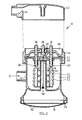
- Reference numeral 10 indicates generally an integral water heating unit with combined shower head in accordance with one preferred embodiment.
- the water inlet 12 includes a restriction 14 which ensures that the volume of water entering the unit 10 can not exceed the volume escaping from the unit.
- Water passes via a nozzle 16 which atomizes the water (not shown) before leaving the unit via the shower rose head 18. This process of atomizing the water through nozzle 16 is a vital factor in the safe operation of the unit 10 since current leakage to the water is dissipated almost entirely.
- the heating chamber 20 can be seen with the coiled element 22 in position on the element support assembly 24.
- the element 22 is a coiled non-ferrous open or bare element which is wound around the support assembly 24 which is preferably moulded from a heat resistant thermo plastics material which is light weight, extremely strong and able to withstand temperatures up to 400 degrees centigrade.
- the support assembly 24 is further composed of four separate identical segments which interlock on assembly. The individual segments themselves have holes 26 to enable free passage of the water and thus enable the water to come into contact with over 90 percent of the surface area of the element.
- the electrical switching mechanism of the invention is a further novel arrangement and is clearly illustrated in Fig.2.
- a primary pair of contacts 28 are mounted in a watertight manner through a rigid support washer 30 to a flexible diaphragm 32, which diaphragm forms the roof portion of the heating chamber 20.
- the lower portions of the terminals 28 fasten to the free ends of the element 22 and a semi-rigid wire support (not shown) serves to secure the elements support assembly 24 to the flexible diaphragm 32 in spaced apart relationship but such that the element 22 and support 24 move up and down in sympathy with the diaphragm 32.
- the contact cap assembly 34 is securely screwed on to the body of the unit by means of corresponding screw threads during assembly.
- the diaphragm 32 is thus clamped between the contact cap 34 and the body in sealing abutment.
- the contact cap assembly 34 includes secondary contacts 36, aligned so as to correspond with the primary contacts 28.
- the unit is in an inoperative mode where, under the influence of gravity, the element and support assembly 22 and 24 respectively, pull the diaphragm 32 downwards thus holding contacts 28 and 36 apart. Under the influence of water pressure in the heating chamber 20, the diaphragm 32 is forced upwards causing the contacts 28 and 36 to engage and thereby energize the element 22.
- the contact cap 34 further includes an earth terminal 38 to which is attached a wire 39 which passes through the diaphragm 32 and is free floating in the area 40.
- This earth wire is an additional safety feature intended to minimize current leakage even further.
- the upper portions of contacts 36 and 38 are adapted to receive the incoming wires being earth, neutral and line respectively.
- the cable passes through a terminal cover 42 which includes a threaded coupling to receive a cable gland.
- the cover 42 is rotatable relative to the unit thus allowing greater freedom in cable positioning during installation.
- the inlet to the cover 42 includes a restriction 44 which will tend to minimize the possibility of water entering the area of the electrical contacts from this source.
- the contact cap 34 includes a recessed well 46 into which such water can flow to keep it away from the contacts.
- the shafts of the terminals are knurled vertically where they pass through the contact cap, thus locking them in position.
- a further novel aspect of the invention is seen in the removable shower head or rose cap 18 which has a quick release thread such that it will release from the unit in approximately a quarter turn.
- the rose cap 18 includes an integrally moulded sealing formation 48 which removes the necessity for a rubber sealing ring or the like which can become detached and lost. The sealing is automatic as the rose head 18 is screwed on to the unit 10.
- the rose cap 18 is further novel in that the outlet holes 50 when seen in cross section are tapered in a manner similar to a funnel. It has been found that this. arrangement allows easy cleaning of the shower rose 18 since dirt lodges in the tapered holes and can be removed merely by releasing the rose 18 from the unit and banging lightly in an inverted position against a firm surface. This contrasts favourably with presently known units where it is normally necessary to clean each hole individually with a pin or similar object.
- the unit has numerous features which combine to make it a significant improvement over the prior art. Not so obvious advantages have been revealed as a result of extensive testing where for example it has been established that, not withstanding the use of the bare element, the maximum current leakage without any earthing arrangement is in the region of .001 to .007 milli-amps. This leakage could never lead to accidental electrocution as has been known to happen with some existing similar units. To the best knowledge of the inventor, this is the first time an arrangement using a bare element has been safely used for the heating of water, with the above earth leakage results.
- the unit is primarily made from moulded durable plastics material which is of course non-conductive or corrosive and can therefore be considered a further safety feature.
- the unit of the invention would normally include an earth arrangement in the form of a length of wire bared at one end and located in the zone of the water outlet and taken separately to earth. This arrangement could be advantageous in areas prone to frequent electrical thunder storms.
Landscapes
- Engineering & Computer Science (AREA)
- Physics & Mathematics (AREA)
- Thermal Sciences (AREA)
- Chemical & Material Sciences (AREA)
- Combustion & Propulsion (AREA)
- Mechanical Engineering (AREA)
- General Engineering & Computer Science (AREA)
- Bathtubs, Showers, And Their Attachments (AREA)
- Instantaneous Water Boilers, Portable Hot-Water Supply Apparatuses, And Control Of Portable Hot-Water Supply Apparatuses (AREA)
- Nozzles (AREA)
Priority Applications (1)
| Application Number | Priority Date | Filing Date | Title |
|---|---|---|---|
| AT85301074T ATE57758T1 (de) | 1984-02-20 | 1985-02-19 | Elektrischer wassererhitzer. |
Applications Claiming Priority (2)
| Application Number | Priority Date | Filing Date | Title |
|---|---|---|---|
| ZW2984 | 1984-02-20 | ||
| ZW29/84A ZW2984A1 (en) | 1984-02-20 | 1984-02-20 | Electrically operated water heating device |
Publications (3)
| Publication Number | Publication Date |
|---|---|
| EP0164816A2 true EP0164816A2 (de) | 1985-12-18 |
| EP0164816A3 EP0164816A3 (en) | 1987-10-07 |
| EP0164816B1 EP0164816B1 (de) | 1990-10-24 |
Family
ID=25590251
Family Applications (1)
| Application Number | Title | Priority Date | Filing Date |
|---|---|---|---|
| EP19850301074 Expired - Lifetime EP0164816B1 (de) | 1984-02-20 | 1985-02-19 | Elektrischer Wassererhitzer |
Country Status (10)
| Country | Link |
|---|---|
| EP (1) | EP0164816B1 (de) |
| AP (1) | AP41A (de) |
| AT (1) | ATE57758T1 (de) |
| AU (1) | AU580578B2 (de) |
| DE (1) | DE3580191D1 (de) |
| ES (1) | ES8603057A1 (de) |
| NZ (1) | NZ211161A (de) |
| PT (1) | PT79976B (de) |
| ZA (1) | ZA851153B (de) |
| ZW (1) | ZW2984A1 (de) |
Cited By (5)
| Publication number | Priority date | Publication date | Assignee | Title |
|---|---|---|---|---|
| FR2602524A1 (fr) * | 1986-08-08 | 1988-02-12 | Bosch Siemens Hausgeraete | Dispositif de chauffage instantane pour le liquide de lavage et de rincage d'un lave-vaisselle ou d'un lave-linge |
| WO1998007522A1 (en) * | 1996-08-19 | 1998-02-26 | Martins Gomes Joao Carlos | Electric shower |
| GB2395899A (en) * | 2002-12-02 | 2004-06-09 | Michael Weir | Instant boiling water tap |
| WO2011066636A3 (en) * | 2009-12-04 | 2011-10-20 | Lorenzetti Claudio Lourenco | Electric shower rose |
| US9052121B2 (en) | 2011-11-30 | 2015-06-09 | Intelligent Energy, Llc | Mobile water heating apparatus |
Family Cites Families (3)
| Publication number | Priority date | Publication date | Assignee | Title |
|---|---|---|---|---|
| AU489438B2 (en) * | 1975-08-01 | 1977-02-03 | Lorenzetti Lorenzo | Water heating device |
| FR2376702A1 (fr) * | 1977-01-10 | 1978-08-04 | Lorenzetti Alexandre | Douche a chauffage electrique |
| IL59790A0 (en) * | 1979-04-17 | 1980-06-30 | Kozyheat Ltd | Water heater and regulating valve for use therewith |
-
1984
- 1984-02-20 ZW ZW29/84A patent/ZW2984A1/xx unknown
-
1985
- 1985-02-14 AU AU38719/85A patent/AU580578B2/en not_active Ceased
- 1985-02-15 PT PT79976A patent/PT79976B/pt not_active IP Right Cessation
- 1985-02-15 ZA ZA851153A patent/ZA851153B/xx unknown
- 1985-02-19 AT AT85301074T patent/ATE57758T1/de not_active IP Right Cessation
- 1985-02-19 ES ES540515A patent/ES8603057A1/es not_active Expired
- 1985-02-19 NZ NZ211161A patent/NZ211161A/xx unknown
- 1985-02-19 AP APAP/P/1985/000007A patent/AP41A/en active
- 1985-02-19 DE DE8585301074T patent/DE3580191D1/de not_active Expired - Fee Related
- 1985-02-19 EP EP19850301074 patent/EP0164816B1/de not_active Expired - Lifetime
Cited By (12)
| Publication number | Priority date | Publication date | Assignee | Title |
|---|---|---|---|---|
| FR2602524A1 (fr) * | 1986-08-08 | 1988-02-12 | Bosch Siemens Hausgeraete | Dispositif de chauffage instantane pour le liquide de lavage et de rincage d'un lave-vaisselle ou d'un lave-linge |
| WO1998007522A1 (en) * | 1996-08-19 | 1998-02-26 | Martins Gomes Joao Carlos | Electric shower |
| AU728445B2 (en) * | 1996-08-19 | 2001-01-11 | Lorenzetti S/A Industrias Brasileiras Eletrometalurgicas | Electric shower |
| CN1094797C (zh) * | 1996-08-19 | 2002-11-27 | 乔欧·卡罗斯·马丁斯-哥姆士 | 电子莲蓬头 |
| GB2395899A (en) * | 2002-12-02 | 2004-06-09 | Michael Weir | Instant boiling water tap |
| GB2395899B (en) * | 2002-12-02 | 2005-02-09 | Michael Weir | Instant boiling water tap |
| WO2011066636A3 (en) * | 2009-12-04 | 2011-10-20 | Lorenzetti Claudio Lourenco | Electric shower rose |
| CN102883817A (zh) * | 2009-12-04 | 2013-01-16 | 克劳迪奥·洛伦科·洛伦泽蒂 | 电淋浴器 |
| AP3314A (en) * | 2009-12-04 | 2015-06-30 | Claudio Lourenco Lorenzetti | Electric shower |
| CN102883817B (zh) * | 2009-12-04 | 2015-08-19 | 克劳迪奥·洛伦科·洛伦泽蒂 | 电淋浴器 |
| US9052121B2 (en) | 2011-11-30 | 2015-06-09 | Intelligent Energy, Llc | Mobile water heating apparatus |
| US10451310B2 (en) | 2011-11-30 | 2019-10-22 | Intelligent Energy, Llc | Mobile water heating apparatus |
Also Published As
| Publication number | Publication date |
|---|---|
| DE3580191D1 (de) | 1990-11-29 |
| AP41A (en) | 1989-05-04 |
| EP0164816B1 (de) | 1990-10-24 |
| AP8500007A0 (en) | 1985-02-01 |
| ES540515A0 (es) | 1985-12-01 |
| ZA851153B (en) | 1985-09-25 |
| PT79976B (en) | 1986-10-28 |
| EP0164816A3 (en) | 1987-10-07 |
| ES8603057A1 (es) | 1985-12-01 |
| PT79976A (en) | 1985-03-01 |
| ATE57758T1 (de) | 1990-11-15 |
| ZW2984A1 (en) | 1987-06-24 |
| AU3871985A (en) | 1985-08-29 |
| AU580578B2 (en) | 1989-01-19 |
| NZ211161A (en) | 1989-01-06 |
Similar Documents
| Publication | Publication Date | Title |
|---|---|---|
| US6536458B1 (en) | Device for heating a tap | |
| US4370543A (en) | Shower-sauna instantaneous electric steam or hot water supply unit | |
| GB1577367A (en) | Electric hot plate assemblies | |
| EP0164816A2 (de) | Elektrischer Wassererhitzer | |
| US1731058A (en) | Water heater | |
| KR101709805B1 (ko) | 유체 가열 방법 | |
| US3967545A (en) | Controlling the supply of electric current to a room | |
| CA1262928A (en) | Electrically operated water heating device | |
| US1977156A (en) | Electric heater and thermostat | |
| US3370154A (en) | Electric fluid heater | |
| US1715687A (en) | Thermostatically-controlled fluid heater | |
| US2286470A (en) | Electric teakettle | |
| US2879372A (en) | Heat exchangers | |
| US2026809A (en) | Electric water heater | |
| US4484062A (en) | Heater structure | |
| US1362356A (en) | Instantaneous electbic wateb-heateb | |
| GB2193563A (en) | Liquid heater | |
| US972131A (en) | Electrical heater. | |
| US1702326A (en) | Electric heater | |
| US1734609A (en) | Thermally-controlled heating apparatus | |
| JPS60251342A (ja) | 電気作動温水装置 | |
| SU1741293A1 (ru) | Электрический чайник | |
| US1875928A (en) | Electric heat shut-off for water heaters | |
| US997670A (en) | Electric water-heater. | |
| US1965208A (en) | Water heater |
Legal Events
| Date | Code | Title | Description |
|---|---|---|---|
| PUAI | Public reference made under article 153(3) epc to a published international application that has entered the european phase |
Free format text: ORIGINAL CODE: 0009012 |
|
| AK | Designated contracting states |
Designated state(s): AT BE CH DE FR GB IT LI LU NL SE |
|
| PUAL | Search report despatched |
Free format text: ORIGINAL CODE: 0009013 |
|
| AK | Designated contracting states |
Kind code of ref document: A3 Designated state(s): AT BE CH DE FR GB IT LI LU NL SE |
|
| 17P | Request for examination filed |
Effective date: 19880218 |
|
| RAP1 | Party data changed (applicant data changed or rights of an application transferred) |
Owner name: STEAMY PRODUCTS (PRIVATE) LIMITED |
|
| 17Q | First examination report despatched |
Effective date: 19890803 |
|
| GRAA | (expected) grant |
Free format text: ORIGINAL CODE: 0009210 |
|
| AK | Designated contracting states |
Kind code of ref document: B1 Designated state(s): AT BE CH DE FR GB IT LI LU NL SE |
|
| REF | Corresponds to: |
Ref document number: 57758 Country of ref document: AT Date of ref document: 19901115 Kind code of ref document: T |
|
| ITF | It: translation for a ep patent filed | ||
| REF | Corresponds to: |
Ref document number: 3580191 Country of ref document: DE Date of ref document: 19901129 |
|
| RIN2 | Information on inventor provided after grant (corrected) |
Free format text: HOLLAND, JOHN DAVID |
|
| ET | Fr: translation filed | ||
| PLBE | No opposition filed within time limit |
Free format text: ORIGINAL CODE: 0009261 |
|
| STAA | Information on the status of an ep patent application or granted ep patent |
Free format text: STATUS: NO OPPOSITION FILED WITHIN TIME LIMIT |
|
| 26N | No opposition filed | ||
| PGFP | Annual fee paid to national office [announced via postgrant information from national office to epo] |
Ref country code: CH Payment date: 19920129 Year of fee payment: 8 |
|
| PGFP | Annual fee paid to national office [announced via postgrant information from national office to epo] |
Ref country code: LU Payment date: 19920130 Year of fee payment: 8 |
|
| PGFP | Annual fee paid to national office [announced via postgrant information from national office to epo] |
Ref country code: GB Payment date: 19920212 Year of fee payment: 8 |
|
| PGFP | Annual fee paid to national office [announced via postgrant information from national office to epo] |
Ref country code: SE Payment date: 19920220 Year of fee payment: 8 |
|
| PGFP | Annual fee paid to national office [announced via postgrant information from national office to epo] |
Ref country code: FR Payment date: 19920225 Year of fee payment: 8 |
|
| ITTA | It: last paid annual fee | ||
| PGFP | Annual fee paid to national office [announced via postgrant information from national office to epo] |
Ref country code: NL Payment date: 19920229 Year of fee payment: 8 Ref country code: AT Payment date: 19920229 Year of fee payment: 8 |
|
| PGFP | Annual fee paid to national office [announced via postgrant information from national office to epo] |
Ref country code: DE Payment date: 19920414 Year of fee payment: 8 |
|
| PGFP | Annual fee paid to national office [announced via postgrant information from national office to epo] |
Ref country code: BE Payment date: 19920514 Year of fee payment: 8 |
|
| EPTA | Lu: last paid annual fee | ||
| PG25 | Lapsed in a contracting state [announced via postgrant information from national office to epo] |
Ref country code: LU Free format text: LAPSE BECAUSE OF NON-PAYMENT OF DUE FEES Effective date: 19930219 Ref country code: GB Effective date: 19930219 Ref country code: AT Effective date: 19930219 |
|
| PG25 | Lapsed in a contracting state [announced via postgrant information from national office to epo] |
Ref country code: SE Effective date: 19930220 |
|
| PG25 | Lapsed in a contracting state [announced via postgrant information from national office to epo] |
Ref country code: LI Effective date: 19930228 Ref country code: CH Effective date: 19930228 Ref country code: BE Effective date: 19930228 |
|
| BERE | Be: lapsed |
Owner name: STEAMY PRODUCTS (PRIVATE) LTD Effective date: 19930228 |
|
| PG25 | Lapsed in a contracting state [announced via postgrant information from national office to epo] |
Ref country code: NL Effective date: 19930901 |
|
| GBPC | Gb: european patent ceased through non-payment of renewal fee |
Effective date: 19930219 |
|
| NLV4 | Nl: lapsed or anulled due to non-payment of the annual fee | ||
| PG25 | Lapsed in a contracting state [announced via postgrant information from national office to epo] |
Ref country code: FR Effective date: 19931029 |
|
| REG | Reference to a national code |
Ref country code: CH Ref legal event code: PL |
|
| PG25 | Lapsed in a contracting state [announced via postgrant information from national office to epo] |
Ref country code: DE Effective date: 19931103 |
|
| REG | Reference to a national code |
Ref country code: FR Ref legal event code: ST |
|
| EUG | Se: european patent has lapsed |
Ref document number: 85301074.2 Effective date: 19930912 |