EP0164872A1 - Brûleur fonctionnant sous une faible charge - Google Patents
Brûleur fonctionnant sous une faible charge Download PDFInfo
- Publication number
- EP0164872A1 EP0164872A1 EP85303142A EP85303142A EP0164872A1 EP 0164872 A1 EP0164872 A1 EP 0164872A1 EP 85303142 A EP85303142 A EP 85303142A EP 85303142 A EP85303142 A EP 85303142A EP 0164872 A1 EP0164872 A1 EP 0164872A1
- Authority
- EP
- European Patent Office
- Prior art keywords
- air flow
- burner
- furnace
- low load
- motive
- Prior art date
- Legal status (The legal status is an assumption and is not a legal conclusion. Google has not performed a legal analysis and makes no representation as to the accuracy of the status listed.)
- Granted
Links
- 239000002737 fuel gas Substances 0.000 claims abstract description 19
- 230000002093 peripheral effect Effects 0.000 claims description 6
- 238000010438 heat treatment Methods 0.000 abstract description 31
- 239000000463 material Substances 0.000 abstract description 27
- 238000002474 experimental method Methods 0.000 description 14
- 238000002485 combustion reaction Methods 0.000 description 5
- 230000000694 effects Effects 0.000 description 4
- 239000000446 fuel Substances 0.000 description 2
- 238000005266 casting Methods 0.000 description 1
- 230000003247 decreasing effect Effects 0.000 description 1
- 238000011144 upstream manufacturing Methods 0.000 description 1
Images


Classifications
-
- F—MECHANICAL ENGINEERING; LIGHTING; HEATING; WEAPONS; BLASTING
- F23—COMBUSTION APPARATUS; COMBUSTION PROCESSES
- F23D—BURNERS
- F23D14/00—Burners for combustion of a gas, e.g. of a gas stored under pressure as a liquid
- F23D14/28—Burners for combustion of a gas, e.g. of a gas stored under pressure as a liquid in association with a gaseous fuel source, e.g. acetylene generator, or a container for liquefied gas
-
- F—MECHANICAL ENGINEERING; LIGHTING; HEATING; WEAPONS; BLASTING
- F23—COMBUSTION APPARATUS; COMBUSTION PROCESSES
- F23D—BURNERS
- F23D14/00—Burners for combustion of a gas, e.g. of a gas stored under pressure as a liquid
- F23D14/20—Non-premix gas burners, i.e. in which gaseous fuel is mixed with combustion air on arrival at the combustion zone
- F23D14/22—Non-premix gas burners, i.e. in which gaseous fuel is mixed with combustion air on arrival at the combustion zone with separate air and gas feed ducts, e.g. with ducts running parallel or crossing each other
- F23D14/24—Non-premix gas burners, i.e. in which gaseous fuel is mixed with combustion air on arrival at the combustion zone with separate air and gas feed ducts, e.g. with ducts running parallel or crossing each other at least one of the fluids being submitted to a swirling motion
Definitions
- the present invention relates to a structure of burner, and more particularly to a structure of burners arranged on both sidewalls of a heating furnace having a relatively large width for heating a material conveyed from the inlet side to the outlet side of the furnace by means of a transporting means.
- the burner has a structure wherein a fuel gas is jetted into a heating furnace while being sandwiched between an inner air flow and an outer air flow to form a hollow flame in the furnace.
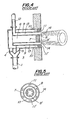
- FIGs. 4 and 5 in the accompanying drawings illustrate the burner. That is, FIG. 4 is a sectional side view of the burner, and FIG. 5 is its front view viewed from the combustion furnace side.
- a proper amount of air based on the amount of supplied fuel is supplied to the burner through a supply passage 1.
- the supply passage 1 is branched into an inner air flow passage 2 and an outer air flow passage 3.
- Air flow rate controlling dampers 4 and 5 are arranged in the inner and outer air flow passages 2 and 3, respectively.
- a baffle 7 is arranged at the end of an inner air flow supply pipe 6 formed in the center axis portion of the burner and has a relatively large area center portion, and several number of inner air flow nozzles 8, 8' ... are arranged in the peripheral portion of the baffle 7.
- An annular outer air flow supply pipe 9 is formed in the peripheral portion of the burner, and has an annular baffle 10 at the end, and the annular baffle 10 has several number of outer air flow nozzles 11, 11' ⁇ .
- Fuel gas which has been controlled to a proper flow rate corresponding to the load of burner, is supplied from a supply passage 12, is flowed through a fuel gas supply pipe 13 arranged between the inner air flow supply pipe 6 and the outer air flow supply pipe 9 and having an annular cross-section, and then is jetted straightforwardly into the furnace through an annular fuel gas nozzle 14 arranged between an inner air flow baffle 7 and the outer air flow baffle 10 arranged at the end of the inner and outer air flow supply pipes. That is, fuel gas is jetted while being sandwiched between the inner air flow and the outer air flow, to form a hollow flame.
- the burner illustrated in FIGs. 4 and 5 has the following characteristic properties.
- a material to be heated is heated in a heating furnace sometimes at a taking out temperature of 1,200°C or sometimes at a taking out temperature of 800°C.
- a material to be heated is sometimes supplied to a heating furnace directly from a casting site under red heat, or is sometimes supplied to a heating furnace after cooled to room temperature.
- the burning air is sometimes previously heated up to 700°C or is sometimes kept to a temperature considerably lower than 700°C.
- the heating furnace must be often operated under a low load of about 10% based on the rated load.
- the object of the present invention is to provide a burner free from the above described drawbacks in the low load burning of a heating furnace. That is, the burner of the present invention is a burner adapted for low load burning, which can form a uniform temperature distribution in the width direction of a heating furnace at the low load burning of about 10% based on the rated load of the burners arranged on both sidewalls of the heating furnace, and can heat uniformly an object material arranged in the width direction of the furnace.
- the feature of the present invention is the provision of a low load burning burner comprising several number of inner air flow nozzles 8, 8' ⁇ ü several number of outer air flow nozzles 11, 11', ⁇ , and a fuel gas nozzle 14; said inner air flow nozzles 8, 8', ⁇ being arranged in the peripheral portion of an inner air flow baffle 7 arranged at the end of the center axis portion of the burner and having a relatively large area center portion; said outer air flow nozzles 11, 11', ⁇ being arranged in an annular outer air flow baffle 10 arranged at the end of the peripheral portion of the burner; and said fuel gas nozzle 14 being constituted by an annular region, which is formed between the inner air flow baffle 7 and the outer air flow baffle 10, such that the fuel gas can be jetted straightforwardly into the furnace through the nozzle, the.
- a motive air supply means which comprises a branched passage 15, a flow rate control valve 16 and a pressurizing fan 17, and is operated during the low load burning of the burner so as to change the branched air flow into a motive air, to supply a proper amount of the motive air under a proper pressure and to jet the motive air straightforwardly through a motive air nozzle 19 arranged in the inner air flow baffle 7, in the outer air flow baffle 10 or in the fuel gas nozzle 14 region.
- FIG. 1 is a sectional side view of a burner according to the present invention
- FIG. 2 is a front view of the burner illustrated in FIG. 1, viewed from the combustion chamber side.
- a branched passage 15 is formed from the upstream position of a branch point of an air supply passage 1 into an inner air flow passage 2 and an outer air flow passage 3, and a flow rate control valve 16 is arranged in the branched passage 15.
- a pressurizing fan 17 is arranged on the delivery side of the valve 16 and converts the branched air flow come out from the valve 16 into a motive air.
- the motive air delivered from the fan 17 is passed through a motive-air-supply pipe 18, and jetted. into a heating furnace through a motive air nozzle 19 arranged at the end of the motive air supply tube 18.
- the term "motive air” herein used means an auxiliary air which gives a straightforwardly advancing movement to a flame.
- the motive air nozzle 19 is arranged in the inner air flow baffle 7, in the outer air flow baffle 10 or in a fuel gas nozzle 14 region, and is preferably arranged at the position above the center of the baffle 7 or 10, or of the fuel gas nozzle 14 region.
- the above described fan 17 is automatically operated to supply a proper amount of motive air to the motive air supply tube 18 under a proper pressure.
- the pressurizing fan 17 has been automatically controlled such that about 3.6%,'based on the rated amount, of air is pressurized to about 300 mmHg and supplied to the motive air supply tube 18.
- FIG..3 shows the result-of an experiment for measuring the effect of the burner of the present invention.
- two burners of the present invention illustrated in FIGs. 1 and 2 were oppositely arranged on both sidewalls of a heating furnace having a width of 12 mm as illustrated in FIG. 3, and a large number of materials to be heated are arranged in the furnace in its width direction at a position 1.1 m above the line connecting the burners and at a position 0.7 m beneath the line as illustrated in FIG. 3, and heated by burning the burners under a low load of 10% based on the rated load.
- the solid line shows the furnace temperature
- the dotted line shows the temperature of the materials arranged above the line connecting the burners and heated
- the dot-dash line shows the temperature of the materials arranged beneath the line and heated in the above described experiment.
- FIG. 6 shows the result of an experiment for measuring the effect of the conventional burner, which experiment has been carried out correspondingly to the experiment of FIG. 3 in order to compare the effect of the burner of the present invention with that of the conventional burner. That is, in this experiment, two conventional burners illustrated in FIGs. 4 and 5 were arranged on both sidewalls of a heating furnace heating a width of 12 m as illustrated in FIG. 6, and a large number of materials to be heated are arranged in the furnace- in its width direction at a position 1.1 m above the line connecting the burners and at a position 0.7 m beneath the line as illustrated in FIG. 6, and heated by burning the burners under a low load of 10% based on the rated load.
- the solid line shows the furnace temperature
- the dotted line shows the temperature of the materials arranged above the line connecting the burners and heated
- the dot-dash line shows the temperatures of the materials arranged beneath the line and heated in the above described experiment.
- the air was flowed such that an outer air was flowed at a rate of 160 Nm 3 /hr (at 5 mm H 2 0), an inner air was not flowed (flow rate: 0 Nm 3 /hr), and a motive air was pressurized to 300 mm H 2 0 and flowed at a rate of 90 Nm 3 /hr. While, in the use of the conventional burner, the air was flowed such that the total air was flowed as an outer air at a rate of 250 Nm 3 /hr (at 10 mm H 2 0), and an inner air was not flowed (flow rate: 0 Nm 3 /hr).
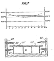
- materials 22, 22', ⁇ to be heated are arranged between both sidewalls of the furnace and conveyed in the furnace by means of a transporting means 21 in a direction perpendicular to the plane of the drawing from its surface side towards its back side.
- Upper burners 23 and 23' and lower burners 24 and 24' are arranged on both sidewalls of the heating furnace, and the materials to be heated are heated, during the moving in the furnace, at their upper surface by means of the upper burners 23 and 23' and at their lower surface by means of the lower burners 24 and 24'.
- FIG. 7 shows the temperature.-distribution in the materials heated by the burners under a low load of 10% based on the rated load.
- the solid line shows the temperature distribution in the heated materials, which temperature distribution is deduced from the experimental value of FIG. 3 in the case where the burners of the present invention are used as the upper burners and the lower burners; and the dotted line shows the temperature distribution in the heated materials, which temperature distribution is deduced from the experimental value of FIG. 6 in the case where the conventional burners are used as the upper burners and the lower burners.
- the burning condition in FIG. 7 is the same as that described in Table 1.
Landscapes
- Engineering & Computer Science (AREA)
- Chemical & Material Sciences (AREA)
- Combustion & Propulsion (AREA)
- Mechanical Engineering (AREA)
- General Engineering & Computer Science (AREA)
- Pre-Mixing And Non-Premixing Gas Burner (AREA)
- Air Supply (AREA)
Applications Claiming Priority (2)
| Application Number | Priority Date | Filing Date | Title |
|---|---|---|---|
| JP91074/84 | 1984-05-09 | ||
| JP59091074A JPS60235910A (ja) | 1984-05-09 | 1984-05-09 | 低負荷燃焼対策のバ−ナ |
Publications (2)
| Publication Number | Publication Date |
|---|---|
| EP0164872A1 true EP0164872A1 (fr) | 1985-12-18 |
| EP0164872B1 EP0164872B1 (fr) | 1988-07-06 |
Family
ID=14016355
Family Applications (1)
| Application Number | Title | Priority Date | Filing Date |
|---|---|---|---|
| EP85303142A Expired EP0164872B1 (fr) | 1984-05-09 | 1985-05-02 | Brûleur fonctionnant sous une faible charge |
Country Status (7)
| Country | Link |
|---|---|
| US (1) | US4626195A (fr) |
| EP (1) | EP0164872B1 (fr) |
| JP (1) | JPS60235910A (fr) |
| KR (1) | KR890001663B1 (fr) |
| BR (1) | BR8502184A (fr) |
| CA (1) | CA1242968A (fr) |
| DE (1) | DE3563651D1 (fr) |
Cited By (2)
| Publication number | Priority date | Publication date | Assignee | Title |
|---|---|---|---|---|
| EP0725251A1 (fr) * | 1995-01-31 | 1996-08-07 | Lbe Beheizungseinrichtungen Gmbh | Procédé et dispositif pour la combustion du combustible gazeux |
| CN101430090B (zh) * | 2007-11-05 | 2012-04-25 | 中南大学 | 旋流弥散燃烧器 |
Families Citing this family (26)
| Publication number | Priority date | Publication date | Assignee | Title |
|---|---|---|---|---|
| DE3715453A1 (de) * | 1987-05-08 | 1988-11-24 | Krupp Polysius Ag | Verfahren und brenner zur verfeuerung von brennstoff |
| US5022849A (en) * | 1988-07-18 | 1991-06-11 | Hitachi, Ltd. | Low NOx burning method and low NOx burner apparatus |
| US4989549A (en) * | 1988-10-11 | 1991-02-05 | Donlee Technologies, Inc. | Ultra-low NOx combustion apparatus |
| JP2776572B2 (ja) * | 1989-07-17 | 1998-07-16 | バブコツク日立株式会社 | 微粉炭バーナ |
| US5110285A (en) * | 1990-12-17 | 1992-05-05 | Union Carbide Industrial Gases Technology Corporation | Fluidic burner |
| US5257927A (en) * | 1991-11-01 | 1993-11-02 | Holman Boiler Works, Inc. | Low NOx burner |
| US5603906A (en) * | 1991-11-01 | 1997-02-18 | Holman Boiler Works, Inc. | Low NOx burner |
| RU2089785C1 (ru) * | 1993-03-22 | 1997-09-10 | Холман Бойлер Уокс, Инк. | Горелка, приспособленная для снижения выделения ядовитых газов (варианты) и способ оптимизации сгорания |
| US5542839A (en) * | 1994-01-31 | 1996-08-06 | Gas Research Institute | Temperature controlled low emissions burner |
| US5772421A (en) * | 1995-05-26 | 1998-06-30 | Canadian Gas Research Institute | Low nox burner |
| DE19653059A1 (de) * | 1996-12-19 | 1998-06-25 | Asea Brown Boveri | Verfahren zum Betrieb eines Brenners |
| US6007325A (en) * | 1998-02-09 | 1999-12-28 | Gas Research Institute | Ultra low emissions burner |
| US5993193A (en) * | 1998-02-09 | 1999-11-30 | Gas Research, Inc. | Variable heat flux low emissions burner |
| US5984665A (en) * | 1998-02-09 | 1999-11-16 | Gas Research Institute | Low emissions surface combustion pilot and flame holder |
| DE19926403A1 (de) * | 1999-06-10 | 2000-12-14 | Ruhrgas Ag | Verfahren und Vorrichtung zum Verbrennen von Brennstoff |
| FR2814796B1 (fr) * | 2000-10-03 | 2003-08-29 | Air Liquide | Bruleur tri-tubes pour fours notamment a verre et a metaux, et procede d'injection de combustible et de carburant par un tel bruleur |
| US7163392B2 (en) * | 2003-09-05 | 2007-01-16 | Feese James J | Three stage low NOx burner and method |
| US7430970B2 (en) * | 2005-06-30 | 2008-10-07 | Larue Albert D | Burner with center air jet |
| KR100608519B1 (ko) * | 2006-04-01 | 2006-08-10 | 주식회사 퓨쳐캐스트 | 주물제작용 모형의 제조방법 |
| US20080096146A1 (en) * | 2006-10-24 | 2008-04-24 | Xianming Jimmy Li | Low NOx staged fuel injection burner for creating plug flow |
| US20080268387A1 (en) * | 2007-04-26 | 2008-10-30 | Takeo Saito | Combustion equipment and burner combustion method |
| US20080280238A1 (en) * | 2007-05-07 | 2008-11-13 | Caterpillar Inc. | Low swirl injector and method for low-nox combustor |
| DE102007025051B4 (de) * | 2007-05-29 | 2011-06-01 | Hitachi Power Europe Gmbh | Hüttengasbrenner |
| US7775791B2 (en) * | 2008-02-25 | 2010-08-17 | General Electric Company | Method and apparatus for staged combustion of air and fuel |
| EP2706232A4 (fr) * | 2011-05-06 | 2015-07-22 | Xiangtan Liyuan Electric Tooling Co Ltd | Appareil pour le chauffage d'un fluide de travail d'un système de génération d'énergie solaire à turbine à gaz |
| JP6632226B2 (ja) * | 2015-06-12 | 2020-01-22 | 三菱日立パワーシステムズ株式会社 | バーナ、燃焼装置、ボイラ及びバーナの制御方法 |
Citations (4)
| Publication number | Priority date | Publication date | Assignee | Title |
|---|---|---|---|---|
| US699705A (en) * | 1901-08-08 | 1902-05-13 | George H Perry | Wagon-gear. |
| US1792021A (en) * | 1921-04-25 | 1931-02-10 | Fred H Loftus | Metallurgical furnace |
| FR2454468A1 (fr) * | 1979-04-17 | 1980-11-14 | Bloom Eng Europa Gmbh | Four a lingots |
| US4281984A (en) * | 1979-07-18 | 1981-08-04 | Kawasaki Steel Corporation | Method of heating a side-burner type heating furnace for slab |
Family Cites Families (3)
| Publication number | Priority date | Publication date | Assignee | Title |
|---|---|---|---|---|
| US1953590A (en) * | 1933-05-01 | 1934-04-03 | Surface Combustion Corp | Gas burner |
| GB699705A (en) * | 1951-06-05 | 1953-11-11 | Wellman Smith Owen Eng Co Ltd | Improvements in or relating to burner apparatus for burning gaseous fuel |
| IT1003846B (it) * | 1973-03-28 | 1976-06-10 | Laidlaw Drew And Co Ltd | Perfezionamento nei bruciatori per bacini fusori per vetr |
-
1984
- 1984-05-09 JP JP59091074A patent/JPS60235910A/ja active Granted
-
1985
- 1985-05-02 EP EP85303142A patent/EP0164872B1/fr not_active Expired
- 1985-05-02 DE DE8585303142T patent/DE3563651D1/de not_active Expired
- 1985-05-08 KR KR1019850003127A patent/KR890001663B1/ko not_active Expired
- 1985-05-08 BR BR8502184A patent/BR8502184A/pt not_active IP Right Cessation
- 1985-05-08 CA CA000481029A patent/CA1242968A/fr not_active Expired
- 1985-05-08 US US06/732,244 patent/US4626195A/en not_active Expired - Fee Related
Patent Citations (4)
| Publication number | Priority date | Publication date | Assignee | Title |
|---|---|---|---|---|
| US699705A (en) * | 1901-08-08 | 1902-05-13 | George H Perry | Wagon-gear. |
| US1792021A (en) * | 1921-04-25 | 1931-02-10 | Fred H Loftus | Metallurgical furnace |
| FR2454468A1 (fr) * | 1979-04-17 | 1980-11-14 | Bloom Eng Europa Gmbh | Four a lingots |
| US4281984A (en) * | 1979-07-18 | 1981-08-04 | Kawasaki Steel Corporation | Method of heating a side-burner type heating furnace for slab |
Cited By (2)
| Publication number | Priority date | Publication date | Assignee | Title |
|---|---|---|---|---|
| EP0725251A1 (fr) * | 1995-01-31 | 1996-08-07 | Lbe Beheizungseinrichtungen Gmbh | Procédé et dispositif pour la combustion du combustible gazeux |
| CN101430090B (zh) * | 2007-11-05 | 2012-04-25 | 中南大学 | 旋流弥散燃烧器 |
Also Published As
| Publication number | Publication date |
|---|---|
| JPS6323447B2 (fr) | 1988-05-17 |
| KR890001663B1 (ko) | 1989-05-12 |
| KR850008396A (ko) | 1985-12-16 |
| CA1242968A (fr) | 1988-10-11 |
| US4626195A (en) | 1986-12-02 |
| DE3563651D1 (en) | 1988-08-11 |
| BR8502184A (pt) | 1986-01-07 |
| EP0164872B1 (fr) | 1988-07-06 |
| JPS60235910A (ja) | 1985-11-22 |
Similar Documents
| Publication | Publication Date | Title |
|---|---|---|
| EP0164872A1 (fr) | Brûleur fonctionnant sous une faible charge | |
| AU673871B2 (en) | Fuel burner apparatus and method employing divergent flow nozzle | |
| KR100643630B1 (ko) | 연료 연소용 버너 및 연료의 연소 방법 | |
| US3880570A (en) | Method and apparatus for reducing nitric in combustion furnaces | |
| CA2304681A1 (fr) | Dispositif de chauffage comprenant une chambre de combustion sans flamme | |
| EP0535846B1 (fr) | Brûleur | |
| US5133192A (en) | Fuel vaporizer | |
| CN1033095A (zh) | 蒸汽机 | |
| US4893475A (en) | Combustion apparatus for a gas turbine | |
| US2391447A (en) | Radiant heater | |
| EP0025219B1 (fr) | Dispositif de chauffage d'un courant de gaz circulant dans un conduit | |
| US4606720A (en) | Pre-vaporizing liquid fuel burner | |
| US5104311A (en) | Autoregulation of primary aeration for atmospheric burners | |
| RU2172895C1 (ru) | Газовая горелка и способ сжигания газообразного топлива | |
| JPS586A (ja) | 燃焼装置 | |
| WO2004065850A1 (fr) | Bruleurs a gaz | |
| CN113286968A (zh) | 用于进行无火焰的分级燃烧的方法和装置 | |
| SU606034A1 (ru) | Радиационный нагреватель | |
| JPS6373009A (ja) | 高負荷燃焼装置 | |
| JP2000283418A (ja) | 低NOxラジアントチューブバーナ及びその運転制御方法 | |
| JPS5914655Y2 (ja) | ガス瞬間湯沸器 | |
| JPH06129611A (ja) | 液体燃料燃焼装置 | |
| JPS5883111A (ja) | 燃焼装置 | |
| JPS60126510A (ja) | 高速液体燃料用燃焼装置 | |
| JPH0360003B2 (fr) |
Legal Events
| Date | Code | Title | Description |
|---|---|---|---|
| PUAI | Public reference made under article 153(3) epc to a published international application that has entered the european phase |
Free format text: ORIGINAL CODE: 0009012 |
|
| AK | Designated contracting states |
Designated state(s): BE DE FR GB NL SE |
|
| 17P | Request for examination filed |
Effective date: 19860522 |
|
| 17Q | First examination report despatched |
Effective date: 19870126 |
|
| GRAA | (expected) grant |
Free format text: ORIGINAL CODE: 0009210 |
|
| AK | Designated contracting states |
Kind code of ref document: B1 Designated state(s): BE DE FR GB NL SE |
|
| REF | Corresponds to: |
Ref document number: 3563651 Country of ref document: DE Date of ref document: 19880811 |
|
| ET | Fr: translation filed | ||
| PLBE | No opposition filed within time limit |
Free format text: ORIGINAL CODE: 0009261 |
|
| STAA | Information on the status of an ep patent application or granted ep patent |
Free format text: STATUS: NO OPPOSITION FILED WITHIN TIME LIMIT |
|
| 26N | No opposition filed | ||
| EAL | Se: european patent in force in sweden |
Ref document number: 85303142.5 |
|
| PGFP | Annual fee paid to national office [announced via postgrant information from national office to epo] |
Ref country code: GB Payment date: 19980423 Year of fee payment: 14 |
|
| PGFP | Annual fee paid to national office [announced via postgrant information from national office to epo] |
Ref country code: FR Payment date: 19980511 Year of fee payment: 14 Ref country code: DE Payment date: 19980511 Year of fee payment: 14 |
|
| PGFP | Annual fee paid to national office [announced via postgrant information from national office to epo] |
Ref country code: SE Payment date: 19980515 Year of fee payment: 14 |
|
| PGFP | Annual fee paid to national office [announced via postgrant information from national office to epo] |
Ref country code: NL Payment date: 19980531 Year of fee payment: 14 |
|
| PGFP | Annual fee paid to national office [announced via postgrant information from national office to epo] |
Ref country code: BE Payment date: 19980714 Year of fee payment: 14 |
|
| PG25 | Lapsed in a contracting state [announced via postgrant information from national office to epo] |
Ref country code: GB Free format text: LAPSE BECAUSE OF NON-PAYMENT OF DUE FEES Effective date: 19990502 |
|
| PG25 | Lapsed in a contracting state [announced via postgrant information from national office to epo] |
Ref country code: SE Free format text: LAPSE BECAUSE OF NON-PAYMENT OF DUE FEES Effective date: 19990503 |
|
| PG25 | Lapsed in a contracting state [announced via postgrant information from national office to epo] |
Ref country code: BE Free format text: LAPSE BECAUSE OF NON-PAYMENT OF DUE FEES Effective date: 19990531 |
|
| BERE | Be: lapsed |
Owner name: NIPPON FURNACE KOGYO KAISHA LTD Effective date: 19990531 Owner name: KAWASAKI STEEL CORP. Effective date: 19990531 |
|
| PG25 | Lapsed in a contracting state [announced via postgrant information from national office to epo] |
Ref country code: NL Free format text: LAPSE BECAUSE OF NON-PAYMENT OF DUE FEES Effective date: 19991201 |
|
| GBPC | Gb: european patent ceased through non-payment of renewal fee |
Effective date: 19990502 |
|
| EUG | Se: european patent has lapsed |
Ref document number: 85303142.5 |
|
| PG25 | Lapsed in a contracting state [announced via postgrant information from national office to epo] |
Ref country code: FR Free format text: LAPSE BECAUSE OF NON-PAYMENT OF DUE FEES Effective date: 20000131 |
|
| NLV4 | Nl: lapsed or anulled due to non-payment of the annual fee |
Effective date: 19991201 |
|
| PG25 | Lapsed in a contracting state [announced via postgrant information from national office to epo] |
Ref country code: DE Free format text: LAPSE BECAUSE OF NON-PAYMENT OF DUE FEES Effective date: 20000301 |
|
| REG | Reference to a national code |
Ref country code: FR Ref legal event code: ST |