EP0164932A2 - Fluidfilter und Ansaugdüse dafür - Google Patents
Fluidfilter und Ansaugdüse dafür Download PDFInfo
- Publication number
- EP0164932A2 EP0164932A2 EP85303489A EP85303489A EP0164932A2 EP 0164932 A2 EP0164932 A2 EP 0164932A2 EP 85303489 A EP85303489 A EP 85303489A EP 85303489 A EP85303489 A EP 85303489A EP 0164932 A2 EP0164932 A2 EP 0164932A2
- Authority
- EP
- European Patent Office
- Prior art keywords
- filter
- suction nozzle
- suction
- inlet opening
- nozzle
- Prior art date
- Legal status (The legal status is an assumption and is not a legal conclusion. Google has not performed a legal analysis and makes no representation as to the accuracy of the status listed.)
- Granted
Links
Images

Classifications
-
- B—PERFORMING OPERATIONS; TRANSPORTING
- B01—PHYSICAL OR CHEMICAL PROCESSES OR APPARATUS IN GENERAL
- B01D—SEPARATION
- B01D29/00—Filters with filtering elements stationary during filtration, e.g. pressure or suction filters, not covered by groups B01D24/00 - B01D27/00; Filtering elements therefor
- B01D29/11—Filters with filtering elements stationary during filtration, e.g. pressure or suction filters, not covered by groups B01D24/00 - B01D27/00; Filtering elements therefor with bag, cage, hose, tube, sleeve or like filtering elements
- B01D29/13—Supported filter elements
- B01D29/23—Supported filter elements arranged for outward flow filtration
-
- B—PERFORMING OPERATIONS; TRANSPORTING
- B01—PHYSICAL OR CHEMICAL PROCESSES OR APPARATUS IN GENERAL
- B01D—SEPARATION
- B01D29/00—Filters with filtering elements stationary during filtration, e.g. pressure or suction filters, not covered by groups B01D24/00 - B01D27/00; Filtering elements therefor
- B01D29/62—Regenerating the filter material in the filter
- B01D29/64—Regenerating the filter material in the filter by scrapers, brushes, nozzles, or the like, acting on the cake side of the filtering element
- B01D29/6438—Regenerating the filter material in the filter by scrapers, brushes, nozzles, or the like, acting on the cake side of the filtering element nozzles
- B01D29/6461—Regenerating the filter material in the filter by scrapers, brushes, nozzles, or the like, acting on the cake side of the filtering element nozzles with a combination of movements with respect to the filtering elements
-
- B—PERFORMING OPERATIONS; TRANSPORTING
- B01—PHYSICAL OR CHEMICAL PROCESSES OR APPARATUS IN GENERAL
- B01D—SEPARATION
- B01D29/00—Filters with filtering elements stationary during filtration, e.g. pressure or suction filters, not covered by groups B01D24/00 - B01D27/00; Filtering elements therefor
- B01D29/62—Regenerating the filter material in the filter
- B01D29/66—Regenerating the filter material in the filter by flushing, e.g. counter-current air-bumps
- B01D29/68—Regenerating the filter material in the filter by flushing, e.g. counter-current air-bumps with backwash arms, shoes or nozzles
- B01D29/686—Regenerating the filter material in the filter by flushing, e.g. counter-current air-bumps with backwash arms, shoes or nozzles with a combination of movements with respect to the filtering elements
-
- B—PERFORMING OPERATIONS; TRANSPORTING
- B01—PHYSICAL OR CHEMICAL PROCESSES OR APPARATUS IN GENERAL
- B01D—SEPARATION
- B01D2201/00—Details relating to filtering apparatus
- B01D2201/08—Regeneration of the filter
- B01D2201/081—Regeneration of the filter using nozzles or suction devices
- B01D2201/082—Suction devices placed on the cake side of the filtering element
-
- B—PERFORMING OPERATIONS; TRANSPORTING
- B01—PHYSICAL OR CHEMICAL PROCESSES OR APPARATUS IN GENERAL
- B01D—SEPARATION
- B01D2201/00—Details relating to filtering apparatus
- B01D2201/08—Regeneration of the filter
- B01D2201/081—Regeneration of the filter using nozzles or suction devices
- B01D2201/084—Nozzles placed on the filtrate side of the filtering element
-
- B—PERFORMING OPERATIONS; TRANSPORTING
- B01—PHYSICAL OR CHEMICAL PROCESSES OR APPARATUS IN GENERAL
- B01D—SEPARATION
- B01D2201/00—Details relating to filtering apparatus
- B01D2201/28—Position of the filtering element
- B01D2201/287—Filtering elements with a vertical or inclined rotation or symmetry axis
Definitions
- the present invention relates to a fluid filter system cleanable by suction. It also relates to suction nozzles usable for such filters.
- a fluid filter system cleanable by suction comprising a filter element fixedly attached to a substantially rigid filter element support mounted in a filter housing and provided with a plurality of openings, at least one suction nozzle having an inlet opening located inclose proximity to said filter element and adapted to move its inlet opening past said filter element in such a way as to cover, in succession, at least some zones of said filter element while producing a suction flow, further comprising guide means for guiding a fluid stream from. the high-pressure raw-fluid space of said filter housing to a low-pressure zone created by said suction nozzle between the inlet opening thereof and that portion of the filter element support which faces said suction nozzle.
- a suction nozzle for a fluid filter system cleanable by suction comprising a filter element fixedly attached to a substantially rigid filter-element support mounted in a filter housing, said suction nozzle having an inlet opening and a tube-like duct located at the inside of said nozzle and attached to a lateral wall thereof, said duct extending between an inlet opening co-planar with said lateral wall, and an outlet opening substantially co-planar with the inlet opening of said suction nozzle.
- the invention further provides a suction nozzle for a fluid filter system cleanable by suction comprising a filter element fixedly attached to a substantially rigid filter-element support mounted in a filter housing, said suction nozzle having twir. inlet openings and a slot cutting across its face between said twin irlet openings in a plane substantially perpendicular tc the plane containing the axes of said inlet openings.
- a suction nozzle 2 arranged inside a filter element 4 mounted on a filter-element support 6, and capable of covering the entire filter element by being adapted, in a way as such known and needing no detailed explanation, to perform a rotary movement as indicated by arrow A, on which is superposed in this particular embodiment a reciprocating movement as indicated by arrows B.
- the suction effect in this and the other embodi- ments deserosed is produced by opening the hollow nozzle shaft 8 to the atmosphers. This procedure, whether carried out manually on amomatically as initiated by a pressure difference building on eween filter inlet and outlet due to progressive clogging also well known and needs no further elaboration.
- the length of the nozzle 2 (which may be one- or multi- armed is such that its inlet opening 10 is in close proximity to the filter element 4. Seen is also a tubelike duct 12 located , and attached to a lateral wall of, the suction no-zle 2. This duct 12 extends slantingly between an inlet opening 14 complanar with the above-mentioned lateral wall and communicating with the raw-water space 16 of the filter, and an outlet opening 18 co-planar with the inlet opening 10 of the suction nozzle 2.
- the suction flow When the suction nozzle 12 is activated, the suction flow, indicated by arrows C, produces a low-pressure region between its inlet opening 10 and that portion of the filter-element support which faces the nozzle 12.
- This low-pressure region causes a water stream from the raw-water space 16 to rush into the duct 12 in-direction of arrow D, guided by the duct and emerging from the latter at the outlet opening 18 thereof.
- This stream impacts the filter element, interacts with the backflushing suction flow C drawn mostly through the holes 20 of the filter-element support 6 and is thereby instrumental in prying loose the filter deposits which are then sucked in through the suction nozzle 2.
- FIG. 3 to 5 Another embodiment of the system according to the invention is illustrated in Figs. 3 to 5.
- the suction nozzle 2 is a twin nozzle, having two inlet openings 10, 10'. The latter may separately lead into the hollow shaft 8 or may unite after some length to form a single duct draining into the shaft 8.
- the tubular duct 12 of the previous embodiment is replaced by a slot 22 provided between the inlet openings 10, 10'.
- This slot 22, as can be seen in Figs. 4 and 5, opens laterally into the raw-water space 16, and frontally into the above-mentioned low-pressure region.
- the directions taken by the suction flow C and the suction-induced water stream D are clearly indicated by the respective arrows.
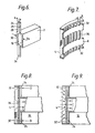
- Yet another embodiment of the system according to the invention is shown in Figs. 6 to 9.
- the nozzle 2 of this embodiment has an inlet opening 10 of a width 2a and is provided with two wing-like projections 24 of a width a. It should be noted that the projections 24 are not centered with respect ti the width 2a of the inlet opening 10, but are offset to such a degree that their edge 26 is aligned with the center line of the inlet opening 10, while their other edge 28 is aligned with the edge 30 of the inlet opening 10. The purpose of these wings 24 and of their offset position will be explained further below.
- Fig. 7 shows a section of the filter-element support 6 of this embodiment. It is seen that, in contradistinction to the previous embodiments, the filter element 2 is located at the outsiae, and not at the inside, of the filter-element support.
- Alsc instead of the perforations 20 of the previous embodiments, there are provided two rows, upper and lower, of relatively low windows 32 and a central row of relatively high windows 34. The windows 32 and 34 are aligned in the axial direction of the cylindrical support 6 and are of a width a.
- the arrangement works as follows: As the nozzle 2, in its rotational movement, sweeps along the rows of windows 32, 34, each window 34 "registers", in succession, with the inlet opening 1C and, at that instant, is exposed to the suction effect of the nozzle which produces the above-mentioned low-pressure region in the immediate vicinity of window 34.
- the windows 32 are alternatingly obturated and exposed to the relatively high pressure of the raw-water space 16 by the wing-like projections 24 of the nozzle 2.
- the window 34 being of a width a, is already-fully exposed to the first half of the 2a-wide inlet opening 10, while the upper and lower windows 32 are not yet obturated by the projection 24 which, as will be remembered, are offset and of a width a only.
- windows 32 thus constitute a connection between the high-pressure raw-water space 16 and the above-mentioned low-pressure region, as a result of which a water stream D is induced to rush through the windows 32 towards the low-pressure region, impacting, and sweeping along, the filter element 4 before being drawn into the suction nozzle 2.
- the nozzle in this particular embodiment performs a rotary movement only. To obtain taller filters, it is, however, possible to mount two or more of these nozzles on top of one another.
Landscapes
- Chemical & Material Sciences (AREA)
- Chemical Kinetics & Catalysis (AREA)
- Filtering Of Dispersed Particles In Gases (AREA)
- Jet Pumps And Other Pumps (AREA)
- Filtration Of Liquid (AREA)
- Nozzles (AREA)
Priority Applications (1)
| Application Number | Priority Date | Filing Date | Title |
|---|---|---|---|
| AT85303489T ATE46274T1 (de) | 1984-06-04 | 1985-05-17 | Fluidfilter und ansaugduese dafuer. |
Applications Claiming Priority (2)
| Application Number | Priority Date | Filing Date | Title |
|---|---|---|---|
| IL71999A IL71999A0 (en) | 1984-06-04 | 1984-06-04 | Fluid filter system and suction nozzle therefor |
| IL71999 | 1984-06-04 |
Publications (3)
| Publication Number | Publication Date |
|---|---|
| EP0164932A2 true EP0164932A2 (de) | 1985-12-18 |
| EP0164932A3 EP0164932A3 (en) | 1987-04-29 |
| EP0164932B1 EP0164932B1 (de) | 1989-09-13 |
Family
ID=11055107
Family Applications (1)
| Application Number | Title | Priority Date | Filing Date |
|---|---|---|---|
| EP85303489A Expired EP0164932B1 (de) | 1984-06-04 | 1985-05-17 | Fluidfilter und Ansaugdüse dafür |
Country Status (5)
| Country | Link |
|---|---|
| US (1) | US4643828A (de) |
| EP (1) | EP0164932B1 (de) |
| AT (1) | ATE46274T1 (de) |
| DE (1) | DE3572929D1 (de) |
| IL (1) | IL71999A0 (de) |
Cited By (7)
| Publication number | Priority date | Publication date | Assignee | Title |
|---|---|---|---|---|
| EP0218034A1 (de) * | 1985-08-19 | 1987-04-15 | INTERATOM Gesellschaft mit beschränkter Haftung | Reinigung von Filterplatten |
| EP0460842A1 (de) * | 1990-06-06 | 1991-12-11 | Filtration Limited | Selbstreinigendes Filter |
| AT397927B (de) * | 1992-05-27 | 1994-08-25 | Chemiefaser Lenzing Ag | Rückspülfähige filtervorrichtung zur filtration hochviskoser flüssigkeiten |
| DE10330518A1 (de) * | 2003-07-05 | 2005-02-03 | Carl Zeiss | Operationsmikroskop mit Fluidstrom-Vorhang |
| ITVR20110119A1 (it) * | 2011-05-27 | 2012-11-28 | Mauro Bonatti | Filtro particolarmente per acque di irrigazione o industriali |
| EP3000517A1 (de) * | 2014-09-19 | 2016-03-30 | Sati S.r.l. | Selbstreinigende filter |
| EP3240462A4 (de) * | 2015-01-04 | 2018-12-05 | Jain Irrigation Systems Limited | Reinigungsvorrichtung zur reinigung von filtersieben |
Families Citing this family (24)
| Publication number | Priority date | Publication date | Assignee | Title |
|---|---|---|---|---|
| US5152891A (en) * | 1990-09-13 | 1992-10-06 | T/M Industrial Supply, Inc. | Self-cleaning strainer |
| US5401396A (en) * | 1991-08-22 | 1995-03-28 | Ga Industries Inc. | Self-cleaning stationary basket strainer |
| US5443726A (en) * | 1993-10-13 | 1995-08-22 | Tm Industrial Supply, Inc. | Self-cleaning filter assembly |
| US5587074A (en) * | 1995-02-17 | 1996-12-24 | H-Tech, Inc. | Fluid filter with enhanced backflush flow |
| US5632903A (en) * | 1995-06-07 | 1997-05-27 | Infinity Research And Development | High volume self-cleaning filter |
| CA2278433C (en) * | 1999-06-22 | 2009-12-01 | Robert Koopmans | Improved filter system |
| US6267879B1 (en) * | 1999-08-11 | 2001-07-31 | Odis Irrigation Equipment Ltd. | Continuous liquid filtering apparatus with multi-layer sintered filtering element |
| CL2008001840A1 (es) * | 2007-06-20 | 2010-09-10 | Parkson Corp | Filtro modular que comprende un medio de filtrado formando una camara con un lado frontal y una estructura de marco interno; un aparato de filtrado, un metodo para operar un aparato de filtrado, un aparato de limpieza de filtro modular |
| CN102712018B (zh) * | 2009-11-12 | 2015-10-07 | 过滤器安全有限公司 | 过滤器近端喷嘴 |
| AT11727U1 (de) * | 2010-03-12 | 2011-04-15 | Lenzing Technik Gmbh | Verfahren zur filtration von fluiden sowie filterapparat zur durchführung des verfahrens |
| US8647516B2 (en) * | 2010-09-03 | 2014-02-11 | Johnny Leon LOVE | Filtration method with self-cleaning filter assembly |
| US8852445B2 (en) * | 2011-10-28 | 2014-10-07 | Alfa Laval Ashbrook Simon-Hartley, Inc | Methods and apparatus for treating water and wastewater employing a cloth disk filter |
| US10905981B2 (en) | 2011-10-28 | 2021-02-02 | Alfa Laval Corporate Ab | Methods and apparatus for treating water and wastewater employing a cloth filter |
| US9561454B2 (en) * | 2012-10-09 | 2017-02-07 | Ovivo Inc. | Debris filter with splitter bar |
| US20140116965A1 (en) * | 2012-11-01 | 2014-05-01 | Machinerie Agricole Bois-Francs Inc. | Separator and method for separating a heterogeneous supply |
| US9314718B2 (en) * | 2013-11-10 | 2016-04-19 | Yamit Filtration & Water Treatment Ltd | Backwash arrangement for cleaning a cylindrical filter screen |
| DE102014219569B4 (de) * | 2014-09-26 | 2017-06-01 | Judo Wasseraufbereitung Gmbh | Wasserfiltereinrichtung mit rückspülbarem Wasserfilter mit Fließgeschwindigkeitsreduktion und Verfahren zum Rückspülen eines Wasserfilters |
| US10245531B2 (en) * | 2015-06-17 | 2019-04-02 | Tm Industrial Supply, Inc. | High-efficiency automatic self-cleaning strainer |
| DE102017002646A1 (de) * | 2017-03-18 | 2018-09-20 | Hydac Process Technology Gmbh | Filtervorrichtung |
| IL258698A (en) * | 2018-04-15 | 2018-05-31 | Amiad Water Systems Ltd | A control mechanism for self-cleaning filter systems |
| US11529573B2 (en) | 2019-04-23 | 2022-12-20 | Greatpyr Resources Llc | Systems and processes employing wet/dry suction filter |
| KR102183820B1 (ko) * | 2020-03-10 | 2020-11-30 | 주식회사 그레넥스 | 섬유상 여과기의 역세정 흡입장치 |
| US12377372B2 (en) | 2021-06-08 | 2025-08-05 | Greatpyr Resources Llc | Apparatus, systems, and processes employing wet/dry suction filter with chicaned suction head |
| CN118807299B (zh) * | 2024-09-14 | 2025-02-11 | 安徽松羽生物系统工程有限公司 | 一种并联式两级除菌过滤器滤芯在线完整性检测工艺 |
Family Cites Families (9)
| Publication number | Priority date | Publication date | Assignee | Title |
|---|---|---|---|---|
| US2066479A (en) * | 1931-06-08 | 1937-01-05 | Vernon W Macisaac | Fluid straining method and apparatus |
| US1945839A (en) * | 1932-04-25 | 1934-02-06 | Maltitz Edmund Von | Filtering apparatus |
| US2182094A (en) * | 1938-09-24 | 1939-12-05 | Francis L Pruyn | Filter bed cleaning |
| US2389329A (en) * | 1941-02-14 | 1945-11-20 | Philip B Streander | Filter bed cleaning |
| US3017029A (en) * | 1957-01-30 | 1962-01-16 | Gen Motors Corp | Self-cleaning filter |
| US3784016A (en) * | 1971-06-30 | 1974-01-08 | Kanagawa Kiki Kogyo Co Ltd | Automatic continuously backflow washing-type filter |
| JPS5232175A (en) * | 1975-09-05 | 1977-03-11 | Asahi Eng Kk | Pneumatic filtration process and device therefor |
| SE420331B (sv) * | 1978-03-08 | 1981-09-28 | Svenska Traeforskningsinst | Forfarande vid en silanordning for rensning av oppningarna i en silplat i form av en trumma samt anordning for utforande av forfarandet |
| DE3235552C2 (de) * | 1982-09-25 | 1986-08-28 | Boll & Kirch Filterbau GmbH, 5014 Kerpen | Rückspülfilter |
-
1984
- 1984-06-04 IL IL71999A patent/IL71999A0/xx not_active IP Right Cessation
-
1985
- 1985-05-14 US US06/733,737 patent/US4643828A/en not_active Expired - Fee Related
- 1985-05-17 AT AT85303489T patent/ATE46274T1/de active
- 1985-05-17 DE DE8585303489T patent/DE3572929D1/de not_active Expired
- 1985-05-17 EP EP85303489A patent/EP0164932B1/de not_active Expired
Cited By (11)
| Publication number | Priority date | Publication date | Assignee | Title |
|---|---|---|---|---|
| EP0218034A1 (de) * | 1985-08-19 | 1987-04-15 | INTERATOM Gesellschaft mit beschränkter Haftung | Reinigung von Filterplatten |
| EP0460842A1 (de) * | 1990-06-06 | 1991-12-11 | Filtration Limited | Selbstreinigendes Filter |
| US5268095A (en) * | 1990-06-06 | 1993-12-07 | Filtration Ltd. | Self-cleaning filter |
| TR26638A (tr) * | 1990-06-06 | 1995-03-15 | Filtration Ltd 2 Ytzhak Barzuz | Kendini temizleyen filtre |
| MD1322B2 (ro) * | 1990-06-06 | 1999-09-30 | Filtration Ltd | Filtru de autoepurare |
| AT397927B (de) * | 1992-05-27 | 1994-08-25 | Chemiefaser Lenzing Ag | Rückspülfähige filtervorrichtung zur filtration hochviskoser flüssigkeiten |
| DE10330518A1 (de) * | 2003-07-05 | 2005-02-03 | Carl Zeiss | Operationsmikroskop mit Fluidstrom-Vorhang |
| DE10330518B4 (de) * | 2003-07-05 | 2006-11-30 | Carl Zeiss Ag | Operationsmikroskop mit Fluidstrom-Vorhang |
| ITVR20110119A1 (it) * | 2011-05-27 | 2012-11-28 | Mauro Bonatti | Filtro particolarmente per acque di irrigazione o industriali |
| EP3000517A1 (de) * | 2014-09-19 | 2016-03-30 | Sati S.r.l. | Selbstreinigende filter |
| EP3240462A4 (de) * | 2015-01-04 | 2018-12-05 | Jain Irrigation Systems Limited | Reinigungsvorrichtung zur reinigung von filtersieben |
Also Published As
| Publication number | Publication date |
|---|---|
| EP0164932B1 (de) | 1989-09-13 |
| US4643828A (en) | 1987-02-17 |
| EP0164932A3 (en) | 1987-04-29 |
| ATE46274T1 (de) | 1989-09-15 |
| DE3572929D1 (en) | 1989-10-19 |
| IL71999A0 (en) | 1984-10-31 |
Similar Documents
| Publication | Publication Date | Title |
|---|---|---|
| EP0164932B1 (de) | Fluidfilter und Ansaugdüse dafür | |
| DE102004030600B4 (de) | Wirbelungs-Staubsammler | |
| US4632757A (en) | Filters cleanable by reverse flushing | |
| AU681786B2 (en) | Air filter assembly for filtering air with particulate matter | |
| US4935136A (en) | Disk filter | |
| DE102004028677B4 (de) | Wirbelungs-Abscheidungsvorrichtung und Staubsauger mit einer solchen Abscheidungsvorrichtung | |
| DE60201019T2 (de) | Staubsauger | |
| DE10035253B4 (de) | Staubsauger | |
| DE3420898A1 (de) | Freistehender kanister-aquarienfilter | |
| DE1282872B (de) | Staubabscheider fuer Staubsauger | |
| US4692247A (en) | Fluid filtering device | |
| DE69816933T2 (de) | Geräuscharmer Staubsauger | |
| EP0284729B1 (de) | Filterelement | |
| DE10328388A1 (de) | Rostanordnung und Zyklonstaubsammelvorrichtung für einen Staubsauger mit einer Rostanordnung | |
| DE8316744U1 (de) | Luftreinigungsvorrichtung | |
| KR102160569B1 (ko) | 메쉬망을 포함한 블레이드 | |
| DE69533242T2 (de) | Verfahren zur Entfernung von Teilchen aus einem Fluidstrom | |
| EP1426093B1 (de) | Abscheider für einen Nassauger | |
| DE3730980C2 (de) | Mit einer Selbstreinigungseinrichtung ausgestatteter Filterapparat für einen Gasstrom | |
| CA2278433A1 (en) | Improved filter system | |
| DE10042671C5 (de) | Saugreinigungswerkzeug mit birnenförmiger Turbinenkammer | |
| US5213684A (en) | Filter apparatus | |
| DE10240622A1 (de) | Saugvorrichtung für einen Staubsauger | |
| EP3723885B1 (de) | Saugadapter für filtersiebe | |
| JPH0214633B2 (de) |
Legal Events
| Date | Code | Title | Description |
|---|---|---|---|
| PUAI | Public reference made under article 153(3) epc to a published international application that has entered the european phase |
Free format text: ORIGINAL CODE: 0009012 |
|
| AK | Designated contracting states |
Designated state(s): AT BE CH DE FR GB IT LI LU NL SE |
|
| PUAL | Search report despatched |
Free format text: ORIGINAL CODE: 0009013 |
|
| AK | Designated contracting states |
Kind code of ref document: A3 Designated state(s): AT BE CH DE FR GB IT LI LU NL SE |
|
| 17P | Request for examination filed |
Effective date: 19870611 |
|
| 17Q | First examination report despatched |
Effective date: 19880225 |
|
| GRAA | (expected) grant |
Free format text: ORIGINAL CODE: 0009210 |
|
| AK | Designated contracting states |
Kind code of ref document: B1 Designated state(s): AT BE CH DE FR GB IT LI LU NL SE |
|
| REF | Corresponds to: |
Ref document number: 46274 Country of ref document: AT Date of ref document: 19890915 Kind code of ref document: T |
|
| REF | Corresponds to: |
Ref document number: 3572929 Country of ref document: DE Date of ref document: 19891019 |
|
| RAP2 | Party data changed (patent owner data changed or rights of a patent transferred) |
Owner name: FILTRATION LIMITED |
|
| ITF | It: translation for a ep patent filed | ||
| ET | Fr: translation filed | ||
| BECN | Be: change of holder's name |
Effective date: 19890913 |
|
| REG | Reference to a national code |
Ref country code: GB Ref legal event code: 732B |
|
| RAP4 | Party data changed (patent owner data changed or rights of a patent transferred) |
Owner name: FILTRATION LIMITED |
|
| NLT1 | Nl: modifications of names registered in virtue of documents presented to the patent office pursuant to art. 16 a, paragraph 1 |
Owner name: FILTRATION LTD. TE HERZLIA, ISRAEL. |
|
| PLBE | No opposition filed within time limit |
Free format text: ORIGINAL CODE: 0009261 |
|
| STAA | Information on the status of an ep patent application or granted ep patent |
Free format text: STATUS: NO OPPOSITION FILED WITHIN TIME LIMIT |
|
| 26N | No opposition filed | ||
| REG | Reference to a national code |
Ref country code: CH Ref legal event code: PFA Free format text: FILTRATION LIMITED |
|
| ITTA | It: last paid annual fee | ||
| EPTA | Lu: last paid annual fee | ||
| EAL | Se: european patent in force in sweden |
Ref document number: 85303489.0 |
|
| PGFP | Annual fee paid to national office [announced via postgrant information from national office to epo] |
Ref country code: AT Payment date: 19960514 Year of fee payment: 12 |
|
| PGFP | Annual fee paid to national office [announced via postgrant information from national office to epo] |
Ref country code: SE Payment date: 19960517 Year of fee payment: 12 |
|
| PGFP | Annual fee paid to national office [announced via postgrant information from national office to epo] |
Ref country code: LU Payment date: 19960601 Year of fee payment: 12 |
|
| PGFP | Annual fee paid to national office [announced via postgrant information from national office to epo] |
Ref country code: CH Payment date: 19960606 Year of fee payment: 12 |
|
| PGFP | Annual fee paid to national office [announced via postgrant information from national office to epo] |
Ref country code: BE Payment date: 19960711 Year of fee payment: 12 |
|
| PGFP | Annual fee paid to national office [announced via postgrant information from national office to epo] |
Ref country code: GB Payment date: 19970515 Year of fee payment: 13 |
|
| PG25 | Lapsed in a contracting state [announced via postgrant information from national office to epo] |
Ref country code: LU Free format text: LAPSE BECAUSE OF NON-PAYMENT OF DUE FEES Effective date: 19970517 Ref country code: AT Effective date: 19970517 |
|
| PG25 | Lapsed in a contracting state [announced via postgrant information from national office to epo] |
Ref country code: SE Effective date: 19970518 |
|
| PGFP | Annual fee paid to national office [announced via postgrant information from national office to epo] |
Ref country code: DE Payment date: 19970523 Year of fee payment: 13 |
|
| PGFP | Annual fee paid to national office [announced via postgrant information from national office to epo] |
Ref country code: FR Payment date: 19970528 Year of fee payment: 13 |
|
| PGFP | Annual fee paid to national office [announced via postgrant information from national office to epo] |
Ref country code: NL Payment date: 19970530 Year of fee payment: 13 |
|
| PG25 | Lapsed in a contracting state [announced via postgrant information from national office to epo] |
Ref country code: LI Free format text: LAPSE BECAUSE OF NON-PAYMENT OF DUE FEES Effective date: 19970531 Ref country code: CH Free format text: LAPSE BECAUSE OF NON-PAYMENT OF DUE FEES Effective date: 19970531 Ref country code: BE Effective date: 19970531 |
|
| BERE | Be: lapsed |
Owner name: FILTRATION LTD Effective date: 19970531 |
|
| REG | Reference to a national code |
Ref country code: CH Ref legal event code: PL |
|
| EUG | Se: european patent has lapsed |
Ref document number: 85303489.0 |
|
| PG25 | Lapsed in a contracting state [announced via postgrant information from national office to epo] |
Ref country code: GB Free format text: LAPSE BECAUSE OF NON-PAYMENT OF DUE FEES Effective date: 19980517 |
|
| PG25 | Lapsed in a contracting state [announced via postgrant information from national office to epo] |
Ref country code: FR Free format text: LAPSE BECAUSE OF NON-PAYMENT OF DUE FEES Effective date: 19980531 |
|
| PG25 | Lapsed in a contracting state [announced via postgrant information from national office to epo] |
Ref country code: NL Free format text: LAPSE BECAUSE OF NON-PAYMENT OF DUE FEES Effective date: 19981201 |
|
| GBPC | Gb: european patent ceased through non-payment of renewal fee |
Effective date: 19980517 |
|
| NLV4 | Nl: lapsed or anulled due to non-payment of the annual fee |
Effective date: 19981201 |
|
| PG25 | Lapsed in a contracting state [announced via postgrant information from national office to epo] |
Ref country code: DE Free format text: LAPSE BECAUSE OF NON-PAYMENT OF DUE FEES Effective date: 19990302 |
|
| REG | Reference to a national code |
Ref country code: FR Ref legal event code: ST |