EP3723885B1 - Saugadapter für filtersiebe - Google Patents
Saugadapter für filtersiebe Download PDFInfo
- Publication number
- EP3723885B1 EP3723885B1 EP19739176.6A EP19739176A EP3723885B1 EP 3723885 B1 EP3723885 B1 EP 3723885B1 EP 19739176 A EP19739176 A EP 19739176A EP 3723885 B1 EP3723885 B1 EP 3723885B1
- Authority
- EP
- European Patent Office
- Prior art keywords
- screen
- suction
- partitioning
- segments
- intake opening
- Prior art date
- Legal status (The legal status is an assumption and is not a legal conclusion. Google has not performed a legal analysis and makes no representation as to the accuracy of the status listed.)
- Active
Links
Images



Classifications
-
- B—PERFORMING OPERATIONS; TRANSPORTING
- B01—PHYSICAL OR CHEMICAL PROCESSES OR APPARATUS IN GENERAL
- B01D—SEPARATION
- B01D29/00—Filters with filtering elements stationary during filtration, e.g. pressure or suction filters, not covered by groups B01D24/00 - B01D27/00; Filtering elements therefor
- B01D29/11—Filters with filtering elements stationary during filtration, e.g. pressure or suction filters, not covered by groups B01D24/00 - B01D27/00; Filtering elements therefor with bag, cage, hose, tube, sleeve or like filtering elements
- B01D29/13—Supported filter elements
- B01D29/15—Supported filter elements arranged for inward flow filtration
-
- B—PERFORMING OPERATIONS; TRANSPORTING
- B01—PHYSICAL OR CHEMICAL PROCESSES OR APPARATUS IN GENERAL
- B01D—SEPARATION
- B01D29/00—Filters with filtering elements stationary during filtration, e.g. pressure or suction filters, not covered by groups B01D24/00 - B01D27/00; Filtering elements therefor
- B01D29/62—Regenerating the filter material in the filter
- B01D29/66—Regenerating the filter material in the filter by flushing, e.g. counter-current air-bumps
- B01D29/668—Regenerating the filter material in the filter by flushing, e.g. counter-current air-bumps with valves, e.g. rotating valves for coaxially placed filtering elements
-
- B—PERFORMING OPERATIONS; TRANSPORTING
- B01—PHYSICAL OR CHEMICAL PROCESSES OR APPARATUS IN GENERAL
- B01D—SEPARATION
- B01D2201/00—Details relating to filtering apparatus
- B01D2201/04—Supports for the filtering elements
- B01D2201/0415—Details of supporting structures
-
- B—PERFORMING OPERATIONS; TRANSPORTING
- B01—PHYSICAL OR CHEMICAL PROCESSES OR APPARATUS IN GENERAL
- B01D—SEPARATION
- B01D2201/00—Details relating to filtering apparatus
- B01D2201/08—Regeneration of the filter
- B01D2201/081—Regeneration of the filter using nozzles or suction devices
- B01D2201/082—Suction devices placed on the cake side of the filtering element
-
- B—PERFORMING OPERATIONS; TRANSPORTING
- B01—PHYSICAL OR CHEMICAL PROCESSES OR APPARATUS IN GENERAL
- B01D—SEPARATION
- B01D29/00—Filters with filtering elements stationary during filtration, e.g. pressure or suction filters, not covered by groups B01D24/00 - B01D27/00; Filtering elements therefor
- B01D29/11—Filters with filtering elements stationary during filtration, e.g. pressure or suction filters, not covered by groups B01D24/00 - B01D27/00; Filtering elements therefor with bag, cage, hose, tube, sleeve or like filtering elements
- B01D29/13—Supported filter elements
- B01D29/23—Supported filter elements arranged for outward flow filtration
- B01D29/232—Supported filter elements arranged for outward flow filtration with corrugated, folded or wound sheets
-
- B—PERFORMING OPERATIONS; TRANSPORTING
- B01—PHYSICAL OR CHEMICAL PROCESSES OR APPARATUS IN GENERAL
- B01D—SEPARATION
- B01D29/00—Filters with filtering elements stationary during filtration, e.g. pressure or suction filters, not covered by groups B01D24/00 - B01D27/00; Filtering elements therefor
- B01D29/50—Filters with filtering elements stationary during filtration, e.g. pressure or suction filters, not covered by groups B01D24/00 - B01D27/00; Filtering elements therefor with multiple filtering elements, characterised by their mutual disposition
- B01D29/52—Filters with filtering elements stationary during filtration, e.g. pressure or suction filters, not covered by groups B01D24/00 - B01D27/00; Filtering elements therefor with multiple filtering elements, characterised by their mutual disposition in parallel connection
Definitions
- the present disclosure relates to the field of self-cleaning filtration systems, and more specifically filtration system using suction scanners.
- Pleated screens are used in all sorts of filtration systems for fluids (e.g. air, fuel, oil, water).
- fluids e.g. air, fuel, oil, water
- US3256995 discloses a self-cleaning filter having convoluted screen
- US2017128860 relates to a filtering means comprising a pleated filter fabric or filter cloth with pleating folds.
- a main advantage of a pleated screen (either flat or cylindrical) over a corresponding non-pleated screen, is a larger screen area per a given flow rate of the screened fluid.
- the suction adapter is for filtration systems having a suction scanner for self-cleaning, and also having space-extensions extending outwardly from a location of the suction scanner and delineated by screen regions unapproachable by intake openings of nozzles of the suction scanner.
- the suction adapter comprises a partitioning adapted to match within a space-extension of a predetermined size and shape, whereby being useful for tunneling a suction power from an intake opening of the suction scanner to a screen region unapproachable by the intake opening.
- the partitioning comprises at least one unit of interconnected partitioning segments.
- a second broad aspect of the presently disclosed subject matter is a filter element according to claim 7 for use in self-cleaning filtration systems having suction scanner for self-cleaning of the filter element, the filter element comprises a screen for removing solid particles from a fluid passing through, and is characterized by comprising at least one suction adapter according to said first broad aspect.
- the suction adapter comprises at least one cavity stationary to the screen and extending across a gap between a predetermined screen-spot located within a cleaning intended area on the screen and between a plane to be approached during suction scanning by an intake opening of a nozzle associated with a suction scanner, the cavity being opened at a first end thereof to the screen-spot and being partitioned from remaining cleaning intended screen areas, and at a second end thereof being opened to the plane, whereby a suction power can be tunneled from the intake opening to the screen-spot when the second end of the cavity is approached by the intake opening.
- the suction adapter comprises a plurality of partitioning segments, wherein each cavity is delimited by one or more partitioning segments.
- the partitioning segments protrude toward the screen from a surface of a perforated sheet opposite a surface thereof to be scanned by an intake opening of the suction scanner.
- the perforated sheet comprises a predetermined number of openings, each in alignment with a second end of a respective cavity wherein openings in the perforated sheet constitute each an integral extension of a respective cavity.
- the screen is a pleated screen.
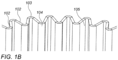
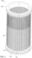
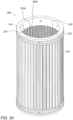
- the pleated screen has a cylindrical-envelop shape sharing a longitudinal axis with a rotatable main tube of the suction scanner, wherein a plurality screen pleats extend between an imaginary internal cylindrical plane tangential to vertical trough lines of the pleats and between an external cylindrical plane tangential to vertical crest lines of the pleats.
- a plurality of partitioning segments are located in respective groups within vertical space-extensions created between each pair of neighboring pleats and between an imaginary cylindrical envelop delineating an area scannable by intake openings of nozzles of the suction scanner or an outer surface of a cylindrical perforated sheet which inner surface thereof is scannable by intake openings of nozzles of the suction scanner.
- a third broad aspect of the presently disclosed subject matter is a self-cleaning filtration system according to claim 18 comprising a suction adapter according to said first broad aspect.
- suction adapter 300 may comprise a plurality of non-horizontal partitioning segments dividing the vertical space extensions 105 into a plurality of special shape cavities, e.g. honeycomb-like cavities, or into a plurality of diagonally oriented cavities.
- Fig. 4 illustrates a vertical section of a filtration assembly 480 comprising a screen element 401 and a suction adapter, for use in a self-cleaning filtration system according to the presently disclosed subject matter.
- the screen element 401 is a pleated screen element, of an embodiment similar to that of the screen element 101 of Fig. 1 .
- a cylindrical perforated sheet 430 is positioned inside the screen 401, tangentially to the troughs 104 of the pleats 102.
- Each pair of neighboring pleats 102 creates a vertical space-extension 105.
- Each vertical space-extension 105 is separated from the inner cylindrical space of the screen by a respective region of the cylindrical perforated sheet 430.
- a group of lateral partitioning segments 433, is located respectively inside each vertical space-extension 105, and is delimited between a pair of neighboring pleats 102 and between the cylindrical perforated sheet 430.
- a plurality of suction openings 434 are formed in the cylindrical perforated sheet 430.
- the openings 434 are arranged in a single helical line, starting clockwise with an opening near the bottom (not shown in the figure) of the cylindrical perforated sheet 430, and ending with an opening near the top of the cylindrical perforated sheet.
- the helical arrangement is such that the openings 433 are spaced in the vertical direction by a thin helical piece 432 (an exemplifying segment in a mid-portion thereof is annotated by a horizontal dotted line 432 for clarity) of the cylindrical envelope 430, starting above said first opening, and ending underneath the last opening.
- suction openings 434 are substantially identical in their shape and dimensions for most of the perforated sheet, the height of some openings near the starting and the ending of the helical line may vary such that the perforations of the perforated sheet end-up parallelly, i.e. equidistant from the top and bottom ends of the cage.
- the openings 434 are dimensioned and spaced such that the number of suction openings 434 per a turn of the helical arrangement is fixed, and such that the first suction opening 434 in each next turn, is aligned with the first suction openings 434 in the previous tum/s.
- the openings 434 thus form vertical columns of suction openings 434, wherein each column of suction openings 434 is separated from a next column by a thin vertical piece 431 extending from nearly the top end to nearly the bottom end of the cylindrical envelope 430 (an exemplifying vertical piece is annotated by a vertical dotted line 431 for clarity).
- the openings 434, the thin helical piece 432, and the plurality of thin vertical pieces 431 are dimensioned such that when the cylindrical perforated sheet 430 is in position inside the screen 101, the vertical pieces 431 are in alignment with and touch or nearly touch respective trough lines 104 of the screen 101.
- the horizontal partitioning segments 433 in a suction adapter are slightly inclined with respect to the vertical pieces 431, wherein their inclination is in match with the inclination of the helical piece 432.
- the suction openings 434, the vertical pieces 431 and the helical piece 432 are either integral with back ends of the partitioning segments of partitioning elements located within the vertical space extensions, or are dimensioned such that when the cylindrical perforated sheet is in a predetermined position with respect to the pleated screen 101, each of the suction openings 434 is aligned with an opening of a respective cavity formed by the lateral partitioning segments 433 (and by the vertical partitioning segments in embodiments in which vertical partitioning segments are provided in the vertical space extensions) of a respective partitioning element.
- Punches 427 may be provided near the top and bottom ends of the filtration assembly 480 for securing it to base and top covers (not shown) which close the internal space of the screen element 401 from its bottom and top ends, respectively.
- springs may be positioned between the perforated cylindrical sheet 430 and the pleated screen 401, providing flexibility to the sheet 430 when pushed against by the nozzle.
- the springs may be mounted in bores, on the troughs 104 of the pleats 102, or the like.
- Fig. 5 illustrates a lateral section through a filtration assembly 580 for use in a self-cleaning filtration system according to the presently disclosed subject matter.
- the filtration assembly 580 is of an embodiment of a pleated screen assembly similar to the embodiment illustrated by Fig. 3C.
- a pleated screen 501 is mounted on a cage.
- the space-extensions 505 are in fluid communication with an inner cylindrical space encompassed by the screen 501. In various embodiments, this fluid communication is through suction openings 534 formed in a cylindrical perforated sheet 530.
- the cylindrical perforated sheet 530 is arranged tangentially to trough lines 504, which are formed in between the pairs of neighboring pleats 502 (in the context of the present disclosure, neighboring pleats are pleats 502 that share a common crest line 503).
- Helical piece 532 of the cylindrical perforated sheet 530 delimits the suction openings 534 at their top and bottom ends (an exemplifying segment of the helical piece is annotated by a curved dotted line 532 for clarity).
- the helical piece 532 is aligned with and touches or nearly touches the back ends of the lateral partitioning segments 533.
- the back ends of the lateral partitioning segments constitute the helical piece 532.
- cavities may be created between the suction openings 534 and the body of the screen 501, one cavity per each opening 534.
- Each cavity provides for as short as possible fluid path between a specific opening 534 and a corresponding spot on the screen.
- a corresponding screen-spot related to a specific opening 534 of the perforated sheet 530 is a screen region extending in front of the specific opening 534 between the front ends of neighboring partitioning segments which their back ends meet (and in various embodiments constitute) respective segments of the helical piece 532 and of the vertical pieces 531, which delimit the opening 534.
- a 'front' side of an element under discussion is the side of the element that faces (and is the closest to) the screen.
- a 'back' side of an element under discussion is the side of the element opposite its front (and is the remotest from the screen).
- a nozzle 550 is shown in a lateral cross section view, aligned in front of a specific cavity formed by a pair of lateral partitioning segments 533 and by respective vertical and lateral pieces 531 and 532 of a suction adapter, which their back ends delimit a respective opening 534 formed in the cylindrical sheet 530.
- An intake opening 551 of the nozzle is aligned with the cavity, such that the cavity serves as a temporal extension for the nozzle, for tunneling the suction force from the nozzle to a specific spot on the screen element.
Landscapes
- Chemical & Material Sciences (AREA)
- Chemical Kinetics & Catalysis (AREA)
- Filtration Of Liquid (AREA)
Claims (19)
- Saugadapter für Filtersysteme mit einem Saugscanner zum Selbstreinigen eines Bereichs eines Siebes durch Absaugen und mit Raumerweiterungen, die sich von einer Position des Saugscanners nach außen erstrecken und durch Siebbereiche abgegrenzt sind, die zwischen Siebtälern und Siebhöhen konturiert sind, wobei an den Siebhöhen eine Innenfläche des Siebes weiter vom nächsten Anfahren der Einlassöffnung der Düse des Saugscanners entfernt ist als in den Siebtälern, sodass ein Siebbereich zwischen einem Siebtal und einer jeweiligen Siebhöhe durch Einlassöffnungen von Düsen des Saugscanners nicht anfahrbar ist, wobei der Saugadapter Folgendes umfasst:
eine Unterteilung, die so angepasst ist, dass sie innerhalb einer Raumerweiterung (105) einer vorbestimmten Größe und Form passt, die zwischen jeweiligen Siebtälern (103) und einer jeweiligen Siebhöhe (104) konturiert ist, wobei die Unterteilung eine Einheit aus miteinander verbundenen Unterteilungssegmenten darstellt und eine Vielzahl von vertikal beabstandeten horizontalen Unterteilungssegmenten (233) umfasst, die durch jeweilige vertikale Segmente (231) miteinander verbunden sind, wobei die Unterteilung somit Hohlräume (234) umfasst, die zwischen den Segmenten (233) gebildet sind. - Saugadapter nach Anspruch 1, ferner ein perforiertes Blech umfassend, das Perforationen aufweist, die mit den Hohlräumen ausgerichtet sind.
- Saugadapter nach Anspruch 2, wobei die Perforationen einer spiralförmigen Linie folgend angeordnet sind, die einer wendelförmigen Scanbahn des Saugscanners entspricht.
- Saugadapter nach Anspruch 1, wobei mindestens eine Einheit aus miteinander verbundenen Unterteilungssegmenten mindestens eine Gruppe aus vertikal beabstandeten horizontalen Unterteilungssegmenten umfasst, die durch ein vertikales Segment miteinander verbunden sind, wobei das vertikale Segment ein vertikales Unterteilungssegment darstellt.
- Saugadapter nach Anspruch 1, wobei die Einheit aus miteinander verbundenen Unterteilungssegmenten mindestens eine Gruppe von vertikal beabstandeten horizontalen Unterteilungssegmenten umfasst, die durch ein perforiertes Blech miteinander verbunden sind, das das verbindende vertikale Segment umfasst.
- Saugadapter nach Anspruch 1, wobei die Unterteilung mindestens ein Unterteilungselement umfasst, wobei das mindestens eine Unterteilungselement eine Vielzahl von Einheiten aus miteinander verbundenen Unterteilungssegmenten umfasst.
- Filterelement zur Verwendung in selbstreinigenden Filtersystemen mit einem Saugscanner zur Selbstreinigung des Filterelements, wobei das Filterelement ein Sieb zum Entfernen von Feststoffpartikeln aus einer hindurchfließenden Flüssigkeit umfasst und dadurch gekennzeichnet ist, dass es mindestens einen Saugadapter nach Anspruch 1 umfasst.
- Filterelement nach Anspruch 7, wobei der Saugadapter mindestens einen Hohlraum umfasst, der an dem Sieb stationär ist und sich über einen Spalt zwischen einem vorbestimmten Siebpunkt, der sich innerhalb eines zu reinigenden Bereichs auf dem Sieb befindet, und zwischen einer Ebene erstreckt, die während des Saugscannens durch eine Einlassöffnung einer Düse, die einem Saugscanner zugeordnet ist, anzufahren ist, wobei der Hohlraum an einem ersten Ende davon zu dem Siebpunkt hin geöffnet ist und von den übrigen zu reinigenden Siebbereichen abgeteilt ist und an einem zweiten Ende davon zu der Ebene hin geöffnet ist, wodurch eine Saugkraft von der Einlassöffnung zu dem Siebpunkt getunnelt werden kann, wenn das zweite Ende des Hohlraums durch die Einlassöffnung angefahren wird.
- Filterelement nach Anspruch 8, wobei der Saugadapter eine Vielzahl von Unterteilungssegmenten umfasst.
- Filterelement nach Anspruch 9, wobei Unterteilungssegmente von einer Oberfläche eines perforierten Blechs, die einer Oberfläche davon gegenüberliegt, die durch eine Einlassöffnung des Saugscanners zu scannen ist, zum Sieb hin vorstehen.
- Filterelement nach Anspruch 8, wobei zwischen der Ebene und den Hohlräumen ein perforiertes Blech liegt.
- Filterelement nach Anspruch 11, wobei das perforierte Blech Öffnungen umfasst, die einer spiralförmigen Linie folgend angeordnet sind.
- Filterelement nach Anspruch 12, wobei das perforierte Blech eine vorbestimmte Anzahl von Öffnungen umfasst, die jeweils mit einem zweiten Ende eines jeweiligen Hohlraums ausgerichtet sind, wobei Öffnungen in dem perforierten Blech jeweils eine integrale Erweiterung eines jeweiligen Hohlraums darstellen.
- Filterelement nach Anspruch 7, wobei das Sieb ein Faltensieb ist, wobei das Faltensieb eine zylinderförmige Hüllform aufweist, die eine Längsachse mit einem drehbaren Hauptrohr des Saugscanners gemeinsam hat, wobei sich eine Vielzahl von Siebfalten zwischen einer imaginären inneren zylindrischen Ebene tangential zu vertikalen Tallinien der Falten und zwischen einer äußeren zylindrischen Ebene tangential zu vertikalen Höhenlinien der Falten erstreckt.
- Filterelement nach Anspruch 14, ein perforiertes Blech umfassend, wobei das perforierte Blech ein zylindrisches perforiertes Blech ist, das innerhalb des Faltensiebes tangential zu den Tallinien des Siebes liegt.
- Filterelement nach Anspruch 14, wobei eine Vielzahl von Unterteilungssegmenten in jeweiligen Gruppen innerhalb vertikaler Raumerweiterungen liegen, die zwischen jedem Paar benachbarter Falten und zwischen einer imaginären zylindrischen Hülle, die einen durch Einlassöffnungen von Düsen des Saugscanners scanbaren Bereich abgrenzt, oder einer äußeren Oberfläche eines zylindrischen perforierten Blechs, dessen innere Oberfläche durch Einlassöffnungen von Düsen des Saugscanners scanbar ist, geschaffen werden.
- Unterteilungselement zur Verwendung in Filtersystemen mit einem Filterelement und einem Saugscanner zur Selbstreinigung des Filterelements, wobei das Unterteilungselement Unterteilungssegmente umfasst, die in Größe und Form angepasst sind, um einen Spalt zwischen einem Siebbereich mit einer Höhe und einer durch eine Einlassöffnung des Saugscanners zu scannenden Ebene oder einer Ebene eines perforierten Blechs, die einer Ebene davon gegenüberliegt, die durch ein Einlassöffnung des Saugscanners zu scannen ist, zu überbrücken, wobei die durch die Einlassöffnung des Saugscanners zu scannende Ebene näher an Tälern des Siebes als an der Höhe liegt, wobei das Unterteilungselement eine Einheit darstellt, die eine Vielzahl von vertikal beabstandeten horizontalen Unterteilungssegmenten (233) umfasst, die durch jeweilige vertikale Segmente (231) miteinander verbunden sind.
- Selbstreinigendes Filtersystem, umfassend:ein Faltensieb; undein Unterteilungselement nach Anspruch 17, wobei das Unterteilungselement einen Saugadapter darstellt, der sich zwischen einer Ebene, die durch mindestens eine Einlassöffnung einer Düse eines Saugscanners scanbar ist, und zwischen zu reinigenden Siebpunkten erstreckt, die sich auf Siebfalten befinden, die von der Ebene entfernt sind.
- Filtersystem, umfassend:eine Kammer, die mindestens einen Fluideinlass in Fluidkommunikation mit einem ersten Raum in der Kammer aufweist, wobei der erste Raum für Ausgangsfluid bestimmt ist;mindestens einen Fluidauslass in Fluidkommunikation mit einem zweiten Raum in der Kammer, wobei der zweite Raum für gefiltertes Fluid bestimmt ist;ein Sieb, das mindestens ein Siebelement umfasst, wobei das Sieb den ersten Raum für Ausgangsfluid und den zweiten Raum für gefiltertes Fluid abteilt und eine Fluidkommunikation zwischen dem ersten und dem zweiten Raum ermöglicht;mindestens eine Saugdüse, die innerhalb des Raums für ungereinigtes Fluid liegt und eine Einlassöffnung zum fokussierten Reinigen eines vorbestimmten Siebbereichs des Siebes aufweist;einen Mechanismus zum Bereitstellen einer jeweiligen Bewegung zwischen der mindestens einen Saugdüse und dem Sieb, wobei ein Abstand zwischen der Einlassöffnung der Saugdüse und dem Sieb pro jedem zu reinigendem Siebpunkt auf dem vorbestimmten Siebbereich jeweils einen Minimalwert aufweist, wenn die Düse während der Bewegung jeden dieser Siebpunkte am nächsten abfährt, wobei mindestens pro Teil des vorbestimmten Siebbereichs der Minimalwert aufgrund eines Spaltes zwischen der Einlassöffnung und dem Sieb im Wesentlichen größer als Null ist, wobei mindestens pro Teil des vorbestimmten Siebbereichs ein Abstand zwischen der Einlassöffnung der Saugdüse und dem Sieb einen Maximalwert aufweist, der größer als der Minimalwert ist, wenn die Düse einen zu reinigenden Siebpunkt am nächsten anfährt, wobei ein Saugadapter an dem Spalt zum Tunneln zwischen der Einlassöffnung und einem zu reinigenden Siebpunkt auf der vorbestimmten Siebfläche bereitgestellt ist, wenn die Einlassöffnung mit einer zweiten Endöffnung eines in dem Saugadapter ausgebildeten Hohlraums ausgerichtet ist, wobei eine erste Endöffnung des Hohlraums auf einen zu reinigenden Siebpunkt ausgerichtet ist, wobei der Saugadapter mindestens ein Unterteilungselement umfasst, das eine Vielzahl von vertikal beabstandeten horizontalen Unterteilungssegmenten umfasst, die durch jeweilige vertikale Segmente miteinander verbunden sind.
Applications Claiming Priority (2)
| Application Number | Priority Date | Filing Date | Title |
|---|---|---|---|
| US201862615164P | 2018-01-09 | 2018-01-09 | |
| PCT/IL2019/050040 WO2019138406A1 (en) | 2018-01-09 | 2019-01-08 | Suction adapter for filtration screens |
Publications (3)
| Publication Number | Publication Date |
|---|---|
| EP3723885A1 EP3723885A1 (de) | 2020-10-21 |
| EP3723885A4 EP3723885A4 (de) | 2021-08-04 |
| EP3723885B1 true EP3723885B1 (de) | 2024-12-04 |
Family
ID=67219050
Family Applications (1)
| Application Number | Title | Priority Date | Filing Date |
|---|---|---|---|
| EP19739176.6A Active EP3723885B1 (de) | 2018-01-09 | 2019-01-08 | Saugadapter für filtersiebe |
Country Status (6)
| Country | Link |
|---|---|
| US (1) | US11235265B2 (de) |
| EP (1) | EP3723885B1 (de) |
| AU (1) | AU2019207591B2 (de) |
| BR (1) | BR112020013566A2 (de) |
| IL (1) | IL272131B2 (de) |
| WO (1) | WO2019138406A1 (de) |
Families Citing this family (2)
| Publication number | Priority date | Publication date | Assignee | Title |
|---|---|---|---|---|
| US11724219B2 (en) | 2022-01-13 | 2023-08-15 | Deere & Company | Bypass valve with variable filter |
| US20250304466A1 (en) * | 2024-03-28 | 2025-10-02 | Amiad Water Systems Ltd. | Filtration system self cleaning mechanism |
Family Cites Families (7)
| Publication number | Priority date | Publication date | Assignee | Title |
|---|---|---|---|---|
| US2835390A (en) * | 1954-09-27 | 1958-05-20 | William R King | Fluid strainers |
| US3256995A (en) | 1963-07-05 | 1966-06-21 | Zurn Ind Inc | Automatic strainer |
| US3511374A (en) * | 1968-11-01 | 1970-05-12 | California & Hawaiian Sugar Co | Screening device |
| SG190715A1 (en) | 2010-12-02 | 2013-07-31 | Amiad Water Systems Ltd | Self cleaning filter system |
| CN102580388B (zh) * | 2012-03-09 | 2015-02-11 | 黄庆 | 一种自洁抽吸式过滤器 |
| DE202014104200U1 (de) * | 2014-06-11 | 2015-09-14 | Boll & Kirch Filterbau Gmbh | Rückspülfilter und Filtereinsatz hierfür |
| DE202016105013U1 (de) * | 2016-09-09 | 2016-09-23 | Nordson Corporation | Filterkerze zum Abscheiden von Verunreinigungen aus einer Kunststoffschmelze |
-
2019
- 2019-01-08 WO PCT/IL2019/050040 patent/WO2019138406A1/en not_active Ceased
- 2019-01-08 US US16/644,881 patent/US11235265B2/en not_active Expired - Fee Related
- 2019-01-08 AU AU2019207591A patent/AU2019207591B2/en active Active
- 2019-01-08 BR BR112020013566-6A patent/BR112020013566A2/pt active Search and Examination
- 2019-01-08 IL IL272131A patent/IL272131B2/en unknown
- 2019-01-08 EP EP19739176.6A patent/EP3723885B1/de active Active
Also Published As
| Publication number | Publication date |
|---|---|
| WO2019138406A1 (en) | 2019-07-18 |
| IL272131B2 (en) | 2024-09-01 |
| IL272131A (en) | 2020-03-31 |
| US11235265B2 (en) | 2022-02-01 |
| BR112020013566A2 (pt) | 2020-12-01 |
| EP3723885A4 (de) | 2021-08-04 |
| AU2019207591A1 (en) | 2020-02-20 |
| US20200330910A1 (en) | 2020-10-22 |
| AU2019207591B2 (en) | 2022-12-08 |
| IL272131B1 (en) | 2024-05-01 |
| EP3723885A1 (de) | 2020-10-21 |
Similar Documents
| Publication | Publication Date | Title |
|---|---|---|
| EP0205407A2 (de) | Scheibenfilter | |
| EP2670506B1 (de) | Rückspülfilter mit spülungsvorrichtung | |
| US6468426B1 (en) | Cyclone separator | |
| US4643828A (en) | Fluid filter system and a suction nozzle therefor | |
| JP6534383B2 (ja) | 逆洗フィルタ及びそのためのフィルタインサート | |
| EP3723885B1 (de) | Saugadapter für filtersiebe | |
| EP0284729B1 (de) | Filterelement | |
| US9795908B2 (en) | Filter systems with dirty air chamber spacer elements and methods of using the same | |
| EP3925682A1 (de) | Eiförmige rohrförmige filterpatronen und filtersysteme damit | |
| SE414372B (sv) | Filter av automatiskt och kontinuerligt medelst returflode sjelvrensande typ | |
| PL245339B1 (pl) | Rura szczelinowa spiralna do filtrów samooczyszczających się, ciśnieniowych oraz filtr szczelinowy samooczyszczający się ciśnieniowy z taką rurą szczelinową | |
| EP0267866B1 (de) | Filter mit multiplen Ringscheiben | |
| US5213684A (en) | Filter apparatus | |
| CN101778660B (zh) | 过滤系统用反冲装置 | |
| US5176829A (en) | Cooperating filter disk units with fingered surfaces | |
| US7396460B2 (en) | Filter element | |
| EP4265314B1 (de) | Wasserfilter/sieb | |
| EP4190425B1 (de) | Reinigungsdüse für ein geschlitztes filtersieb mit selektivität unter 90 mikrometer | |
| RU2048859C1 (ru) | Фильтр для очистки жидкости | |
| JP2026514138A (ja) | プレクリーナ塵除去のための一体型マニホールド | |
| SU1346255A1 (ru) | Центробежный очиститель жидкости | |
| SK397192A3 (en) | Filter | |
| KR20170019271A (ko) | 중공사막 모듈 | |
| KR19980061248U (ko) | 여과지의 집수블럭용 스트레이너 | |
| UA35195A (uk) | Фільтр для тонкої очистки рідин |
Legal Events
| Date | Code | Title | Description |
|---|---|---|---|
| STAA | Information on the status of an ep patent application or granted ep patent |
Free format text: STATUS: THE INTERNATIONAL PUBLICATION HAS BEEN MADE |
|
| PUAI | Public reference made under article 153(3) epc to a published international application that has entered the european phase |
Free format text: ORIGINAL CODE: 0009012 |
|
| STAA | Information on the status of an ep patent application or granted ep patent |
Free format text: STATUS: REQUEST FOR EXAMINATION WAS MADE |
|
| 17P | Request for examination filed |
Effective date: 20200717 |
|
| AK | Designated contracting states |
Kind code of ref document: A1 Designated state(s): AL AT BE BG CH CY CZ DE DK EE ES FI FR GB GR HR HU IE IS IT LI LT LU LV MC MK MT NL NO PL PT RO RS SE SI SK SM TR |
|
| AX | Request for extension of the european patent |
Extension state: BA ME |
|
| DAV | Request for validation of the european patent (deleted) | ||
| DAX | Request for extension of the european patent (deleted) | ||
| A4 | Supplementary search report drawn up and despatched |
Effective date: 20210702 |
|
| RIC1 | Information provided on ipc code assigned before grant |
Ipc: B01D 29/11 20060101AFI20210628BHEP Ipc: B01D 29/15 20060101ALI20210628BHEP Ipc: B01D 29/23 20060101ALI20210628BHEP Ipc: B01D 29/66 20060101ALI20210628BHEP |
|
| STAA | Information on the status of an ep patent application or granted ep patent |
Free format text: STATUS: EXAMINATION IS IN PROGRESS |
|
| 17Q | First examination report despatched |
Effective date: 20221201 |
|
| GRAP | Despatch of communication of intention to grant a patent |
Free format text: ORIGINAL CODE: EPIDOSNIGR1 |
|
| STAA | Information on the status of an ep patent application or granted ep patent |
Free format text: STATUS: GRANT OF PATENT IS INTENDED |
|
| INTG | Intention to grant announced |
Effective date: 20240905 |
|
| GRAS | Grant fee paid |
Free format text: ORIGINAL CODE: EPIDOSNIGR3 |
|
| GRAA | (expected) grant |
Free format text: ORIGINAL CODE: 0009210 |
|
| STAA | Information on the status of an ep patent application or granted ep patent |
Free format text: STATUS: THE PATENT HAS BEEN GRANTED |
|
| AK | Designated contracting states |
Kind code of ref document: B1 Designated state(s): AL AT BE BG CH CY CZ DE DK EE ES FI FR GB GR HR HU IE IS IT LI LT LU LV MC MK MT NL NO PL PT RO RS SE SI SK SM TR |
|
| REG | Reference to a national code |
Ref country code: GB Ref legal event code: FG4D |
|
| REG | Reference to a national code |
Ref country code: CH Ref legal event code: EP |
|
| REG | Reference to a national code |
Ref country code: DE Ref legal event code: R096 Ref document number: 602019062955 Country of ref document: DE |
|
| REG | Reference to a national code |
Ref country code: IE Ref legal event code: FG4D |
|
| REG | Reference to a national code |
Ref country code: LT Ref legal event code: MG9D |
|
| REG | Reference to a national code |
Ref country code: NL Ref legal event code: MP Effective date: 20241204 |
|
| PG25 | Lapsed in a contracting state [announced via postgrant information from national office to epo] |
Ref country code: HR Free format text: LAPSE BECAUSE OF FAILURE TO SUBMIT A TRANSLATION OF THE DESCRIPTION OR TO PAY THE FEE WITHIN THE PRESCRIBED TIME-LIMIT Effective date: 20241204 |
|
| PG25 | Lapsed in a contracting state [announced via postgrant information from national office to epo] |
Ref country code: FI Free format text: LAPSE BECAUSE OF FAILURE TO SUBMIT A TRANSLATION OF THE DESCRIPTION OR TO PAY THE FEE WITHIN THE PRESCRIBED TIME-LIMIT Effective date: 20241204 |
|
| PG25 | Lapsed in a contracting state [announced via postgrant information from national office to epo] |
Ref country code: BG Free format text: LAPSE BECAUSE OF FAILURE TO SUBMIT A TRANSLATION OF THE DESCRIPTION OR TO PAY THE FEE WITHIN THE PRESCRIBED TIME-LIMIT Effective date: 20241204 |
|
| PG25 | Lapsed in a contracting state [announced via postgrant information from national office to epo] |
Ref country code: ES Free format text: LAPSE BECAUSE OF FAILURE TO SUBMIT A TRANSLATION OF THE DESCRIPTION OR TO PAY THE FEE WITHIN THE PRESCRIBED TIME-LIMIT Effective date: 20241204 |
|
| PG25 | Lapsed in a contracting state [announced via postgrant information from national office to epo] |
Ref country code: NO Free format text: LAPSE BECAUSE OF FAILURE TO SUBMIT A TRANSLATION OF THE DESCRIPTION OR TO PAY THE FEE WITHIN THE PRESCRIBED TIME-LIMIT Effective date: 20250304 |
|
| PG25 | Lapsed in a contracting state [announced via postgrant information from national office to epo] |
Ref country code: LV Free format text: LAPSE BECAUSE OF FAILURE TO SUBMIT A TRANSLATION OF THE DESCRIPTION OR TO PAY THE FEE WITHIN THE PRESCRIBED TIME-LIMIT Effective date: 20241204 Ref country code: GR Free format text: LAPSE BECAUSE OF FAILURE TO SUBMIT A TRANSLATION OF THE DESCRIPTION OR TO PAY THE FEE WITHIN THE PRESCRIBED TIME-LIMIT Effective date: 20250305 |
|
| PG25 | Lapsed in a contracting state [announced via postgrant information from national office to epo] |
Ref country code: RS Free format text: LAPSE BECAUSE OF FAILURE TO SUBMIT A TRANSLATION OF THE DESCRIPTION OR TO PAY THE FEE WITHIN THE PRESCRIBED TIME-LIMIT Effective date: 20250304 |
|
| PG25 | Lapsed in a contracting state [announced via postgrant information from national office to epo] |
Ref country code: NL Free format text: LAPSE BECAUSE OF FAILURE TO SUBMIT A TRANSLATION OF THE DESCRIPTION OR TO PAY THE FEE WITHIN THE PRESCRIBED TIME-LIMIT Effective date: 20241204 |
|
| REG | Reference to a national code |
Ref country code: AT Ref legal event code: MK05 Ref document number: 1747560 Country of ref document: AT Kind code of ref document: T Effective date: 20241204 |
|
| PG25 | Lapsed in a contracting state [announced via postgrant information from national office to epo] |
Ref country code: SM Free format text: LAPSE BECAUSE OF FAILURE TO SUBMIT A TRANSLATION OF THE DESCRIPTION OR TO PAY THE FEE WITHIN THE PRESCRIBED TIME-LIMIT Effective date: 20241204 |
|
| PG25 | Lapsed in a contracting state [announced via postgrant information from national office to epo] |
Ref country code: PL Free format text: LAPSE BECAUSE OF FAILURE TO SUBMIT A TRANSLATION OF THE DESCRIPTION OR TO PAY THE FEE WITHIN THE PRESCRIBED TIME-LIMIT Effective date: 20241204 |
|
| PG25 | Lapsed in a contracting state [announced via postgrant information from national office to epo] |
Ref country code: IS Free format text: LAPSE BECAUSE OF FAILURE TO SUBMIT A TRANSLATION OF THE DESCRIPTION OR TO PAY THE FEE WITHIN THE PRESCRIBED TIME-LIMIT Effective date: 20250404 |
|
| PG25 | Lapsed in a contracting state [announced via postgrant information from national office to epo] |
Ref country code: PT Free format text: LAPSE BECAUSE OF FAILURE TO SUBMIT A TRANSLATION OF THE DESCRIPTION OR TO PAY THE FEE WITHIN THE PRESCRIBED TIME-LIMIT Effective date: 20250404 |
|
| PG25 | Lapsed in a contracting state [announced via postgrant information from national office to epo] |
Ref country code: EE Free format text: LAPSE BECAUSE OF FAILURE TO SUBMIT A TRANSLATION OF THE DESCRIPTION OR TO PAY THE FEE WITHIN THE PRESCRIBED TIME-LIMIT Effective date: 20241204 |
|
| PG25 | Lapsed in a contracting state [announced via postgrant information from national office to epo] |
Ref country code: RO Free format text: LAPSE BECAUSE OF FAILURE TO SUBMIT A TRANSLATION OF THE DESCRIPTION OR TO PAY THE FEE WITHIN THE PRESCRIBED TIME-LIMIT Effective date: 20241204 Ref country code: AT Free format text: LAPSE BECAUSE OF FAILURE TO SUBMIT A TRANSLATION OF THE DESCRIPTION OR TO PAY THE FEE WITHIN THE PRESCRIBED TIME-LIMIT Effective date: 20241204 |
|
| PG25 | Lapsed in a contracting state [announced via postgrant information from national office to epo] |
Ref country code: SK Free format text: LAPSE BECAUSE OF FAILURE TO SUBMIT A TRANSLATION OF THE DESCRIPTION OR TO PAY THE FEE WITHIN THE PRESCRIBED TIME-LIMIT Effective date: 20241204 |
|
| PG25 | Lapsed in a contracting state [announced via postgrant information from national office to epo] |
Ref country code: CZ Free format text: LAPSE BECAUSE OF FAILURE TO SUBMIT A TRANSLATION OF THE DESCRIPTION OR TO PAY THE FEE WITHIN THE PRESCRIBED TIME-LIMIT Effective date: 20241204 |
|
| PG25 | Lapsed in a contracting state [announced via postgrant information from national office to epo] |
Ref country code: IT Free format text: LAPSE BECAUSE OF FAILURE TO SUBMIT A TRANSLATION OF THE DESCRIPTION OR TO PAY THE FEE WITHIN THE PRESCRIBED TIME-LIMIT Effective date: 20241204 |
|
| REG | Reference to a national code |
Ref country code: DE Ref legal event code: R119 Ref document number: 602019062955 Country of ref document: DE |
|
| REG | Reference to a national code |
Ref country code: CH Ref legal event code: PL |
|
| PG25 | Lapsed in a contracting state [announced via postgrant information from national office to epo] |
Ref country code: SE Free format text: LAPSE BECAUSE OF FAILURE TO SUBMIT A TRANSLATION OF THE DESCRIPTION OR TO PAY THE FEE WITHIN THE PRESCRIBED TIME-LIMIT Effective date: 20241204 |
|
| PG25 | Lapsed in a contracting state [announced via postgrant information from national office to epo] |
Ref country code: MC Free format text: LAPSE BECAUSE OF FAILURE TO SUBMIT A TRANSLATION OF THE DESCRIPTION OR TO PAY THE FEE WITHIN THE PRESCRIBED TIME-LIMIT Effective date: 20241204 Ref country code: LU Free format text: LAPSE BECAUSE OF NON-PAYMENT OF DUE FEES Effective date: 20250108 |
|
| PG25 | Lapsed in a contracting state [announced via postgrant information from national office to epo] |
Ref country code: DK Free format text: LAPSE BECAUSE OF FAILURE TO SUBMIT A TRANSLATION OF THE DESCRIPTION OR TO PAY THE FEE WITHIN THE PRESCRIBED TIME-LIMIT Effective date: 20241204 Ref country code: DE Free format text: LAPSE BECAUSE OF NON-PAYMENT OF DUE FEES Effective date: 20250801 |
|
| PLBE | No opposition filed within time limit |
Free format text: ORIGINAL CODE: 0009261 |
|
| STAA | Information on the status of an ep patent application or granted ep patent |
Free format text: STATUS: NO OPPOSITION FILED WITHIN TIME LIMIT |
|
| PG25 | Lapsed in a contracting state [announced via postgrant information from national office to epo] |
Ref country code: BE Free format text: LAPSE BECAUSE OF NON-PAYMENT OF DUE FEES Effective date: 20250131 |
|
| PG25 | Lapsed in a contracting state [announced via postgrant information from national office to epo] |
Ref country code: CH Free format text: LAPSE BECAUSE OF NON-PAYMENT OF DUE FEES Effective date: 20250131 |
|
| REG | Reference to a national code |
Ref country code: BE Ref legal event code: MM Effective date: 20250131 |
|
| 26N | No opposition filed |
Effective date: 20250905 |
|
| GBPC | Gb: european patent ceased through non-payment of renewal fee |
Effective date: 20250304 |
|
| PG25 | Lapsed in a contracting state [announced via postgrant information from national office to epo] |
Ref country code: GB Free format text: LAPSE BECAUSE OF NON-PAYMENT OF DUE FEES Effective date: 20250304 |
|
| PG25 | Lapsed in a contracting state [announced via postgrant information from national office to epo] |
Ref country code: FR Free format text: LAPSE BECAUSE OF NON-PAYMENT OF DUE FEES Effective date: 20250204 |
|
| PG25 | Lapsed in a contracting state [announced via postgrant information from national office to epo] |
Ref country code: IE Free format text: LAPSE BECAUSE OF NON-PAYMENT OF DUE FEES Effective date: 20250108 |