EP0164990A2 - Automatische Spann- und Indexiervorrichtung - Google Patents
Automatische Spann- und Indexiervorrichtung Download PDFInfo
- Publication number
- EP0164990A2 EP0164990A2 EP85303918A EP85303918A EP0164990A2 EP 0164990 A2 EP0164990 A2 EP 0164990A2 EP 85303918 A EP85303918 A EP 85303918A EP 85303918 A EP85303918 A EP 85303918A EP 0164990 A2 EP0164990 A2 EP 0164990A2
- Authority
- EP
- European Patent Office
- Prior art keywords
- guide tube
- pin
- split
- robotic tool
- tool
- Prior art date
- Legal status (The legal status is an assumption and is not a legal conclusion. Google has not performed a legal analysis and makes no representation as to the accuracy of the status listed.)
- Withdrawn
Links
Images



Classifications
-
- B—PERFORMING OPERATIONS; TRANSPORTING
- B25—HAND TOOLS; PORTABLE POWER-DRIVEN TOOLS; MANIPULATORS
- B25J—MANIPULATORS; CHAMBERS PROVIDED WITH MANIPULATION DEVICES
- B25J3/00—Manipulators of leader-follower type, i.e. both controlling unit and controlled unit perform corresponding spatial movements
-
- B—PERFORMING OPERATIONS; TRANSPORTING
- B23—MACHINE TOOLS; METAL-WORKING NOT OTHERWISE PROVIDED FOR
- B23P—METAL-WORKING NOT OTHERWISE PROVIDED FOR; COMBINED OPERATIONS; UNIVERSAL MACHINE TOOLS
- B23P19/00—Machines for simply fitting together or separating metal parts or objects, or metal and non-metal parts, whether or not involving some deformation; Tools or devices therefor so far as not provided for in other classes
- B23P19/02—Machines for simply fitting together or separating metal parts or objects, or metal and non-metal parts, whether or not involving some deformation; Tools or devices therefor so far as not provided for in other classes for connecting objects by press fit or for detaching same
- B23P19/025—For detaching only
-
- Y—GENERAL TAGGING OF NEW TECHNOLOGICAL DEVELOPMENTS; GENERAL TAGGING OF CROSS-SECTIONAL TECHNOLOGIES SPANNING OVER SEVERAL SECTIONS OF THE IPC; TECHNICAL SUBJECTS COVERED BY FORMER USPC CROSS-REFERENCE ART COLLECTIONS [XRACs] AND DIGESTS
- Y10—TECHNICAL SUBJECTS COVERED BY FORMER USPC
- Y10T—TECHNICAL SUBJECTS COVERED BY FORMER US CLASSIFICATION
- Y10T29/00—Metal working
- Y10T29/49—Method of mechanical manufacture
- Y10T29/49718—Repairing
- Y10T29/49721—Repairing with disassembling
- Y10T29/4973—Replacing of defective part
-
- Y—GENERAL TAGGING OF NEW TECHNOLOGICAL DEVELOPMENTS; GENERAL TAGGING OF CROSS-SECTIONAL TECHNOLOGIES SPANNING OVER SEVERAL SECTIONS OF THE IPC; TECHNICAL SUBJECTS COVERED BY FORMER USPC CROSS-REFERENCE ART COLLECTIONS [XRACs] AND DIGESTS
- Y10—TECHNICAL SUBJECTS COVERED BY FORMER USPC
- Y10T—TECHNICAL SUBJECTS COVERED BY FORMER US CLASSIFICATION
- Y10T29/00—Metal working
- Y10T29/49—Method of mechanical manufacture
- Y10T29/49815—Disassembling
- Y10T29/49821—Disassembling by altering or destroying work part or connector
-
- Y—GENERAL TAGGING OF NEW TECHNOLOGICAL DEVELOPMENTS; GENERAL TAGGING OF CROSS-SECTIONAL TECHNOLOGIES SPANNING OVER SEVERAL SECTIONS OF THE IPC; TECHNICAL SUBJECTS COVERED BY FORMER USPC CROSS-REFERENCE ART COLLECTIONS [XRACs] AND DIGESTS
- Y10—TECHNICAL SUBJECTS COVERED BY FORMER USPC
- Y10T—TECHNICAL SUBJECTS COVERED BY FORMER US CLASSIFICATION
- Y10T29/00—Metal working
- Y10T29/53—Means to assemble or disassemble
- Y10T29/531—Nuclear device
-
- Y—GENERAL TAGGING OF NEW TECHNOLOGICAL DEVELOPMENTS; GENERAL TAGGING OF CROSS-SECTIONAL TECHNOLOGIES SPANNING OVER SEVERAL SECTIONS OF THE IPC; TECHNICAL SUBJECTS COVERED BY FORMER USPC CROSS-REFERENCE ART COLLECTIONS [XRACs] AND DIGESTS
- Y10—TECHNICAL SUBJECTS COVERED BY FORMER USPC
- Y10T—TECHNICAL SUBJECTS COVERED BY FORMER US CLASSIFICATION
- Y10T29/00—Metal working
- Y10T29/53—Means to assemble or disassemble
- Y10T29/534—Multiple station assembly or disassembly apparatus
Definitions
- This invention relates generally to nuclear reactors and more particularly concerns the replacement of old split-pin assemblies by new split-pin assemblies in the lower guide tubes of nuclear reactors having lower guide tubes (LGT).
- LGT lower guide tubes
- the LGT has an upper flange and a lower flange and is of substantial length, typically 124 inches to 150 inches, between the flanges.
- the old split-pin assembly is secured, and the new split-pin assembly is to be secured, in counterbores in the lower flange.
- the LGT and the old split-pin assemblies are highly radioactive.
- the replacement is effected in a work station under a pool of borated water in a plurality of successive operations, each operation being carried out preferably by a robotic tool remotely actuable from a robotic command center above the pool which is free of the hazards of radioactivity.
- the robotic tools are mounted on cluster plates on a strong back and predominantly are transportable on tracks into operating position.
- the cluster plates and the tools which they carry may be removed from the strong back so that maintenance and repair of separate tools may be carried out without removing the whole work station.
- the tools are oriented on different sides of the LGT.
- the lower flange of the LGT carries at least two split-pin assemblies spaced 180° peripherally around the lower flange. It is then necessary that the LGT be rotated to enable processing by different tools and also to enable replacement of both assemblies.
- the LGT is composed of stainless steel and is not only large but is also heavy.
- the fabricating of an LGT involves intricate machining operations which consume long intervals of time.
- a typical LGT as completed may cost $80,000.
- the positioning of an LGT for processing and the rotation of the LGT during processing, without damage to the LGT, presents serious problems.
- This robotic tool shall also have the facility of rotating the LGT as may be necessary to orient the LGT for treatment by different tools and to enable the replacement of both old split-pin assemblies with a single set of robotic tools.
- the invention in its broad form comprises a robotic tool for use in the replacement of old split-pin assemblies of a guide tube of a nuclear reactor by new split-pin assemblies, said old split-pin assemblies and said guide tube being radioactive and said robotic tool to operate under a pool of water, the said robotic tool including means, to be connected to said guide tube, for suspending said guide tube in position to be processed to effect said replacement, and means, connected to said suspending means, for rotating said guide tube.
- a robotic clamp-and-index tool having upper and lower level members or decks.
- the upper deck includes facilities accessible to the crane for temporarily suspending the LGT.
- the LGT is suspended on pins which pass through diagonal bolt holes in the upper flange.
- the crane is disconnected from the bail on the LGT; the bail remains connected to the LGT.
- the upper-level member includes lift means for raising the LGT, so that it clears the pins, and facilities for moving the LGT inwardly to a position where it may be processed for replacement.
- the lift means is provided with a yoke which engages the bail to manipulate the LGT.
- the yoke remains connected to the bail during the processing of the LGT and serves for raising the LGT, after the complete replacement, and returning it to the outer pins where it may be removed by the crane for reinstallation in the upper internals.
- the LGT is suspended on pins in the inner processing position.
- the upper-level member also includes means for rotating the LGT. When the LGT is to be rotated, it is first raised by the lifting means to clear the pins. The distance between the upper and lower level members is such that the lower flange is in position for processing in the lower-level member.
- the lower-level member includes means for clamping the lower flange.
- a pin-puller and expellor is mounted on the lower-level member pivotal from an "in” position and an "out” position. In the "in” position the pin-puller and expellor is centered directly under the lower counterbore.
- the pin-puller and expellor has a collet which engages the shank of the split-pin during the machining and pulls the pin fragment out after the severing.
- the pin-puller and expellor also has a plunger which passes into the collet after the pin fragment is pulled out and expels the fragment into a trash chute. When there is no split-pin in the counterbore, the plunger is injected into the counterbore and serves to center the LGT precisely for processing and to hold the LGT centered while a new nut is being torqued onto a new split-pin.
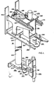
- the clamp-and-index tool 211 includes an elongated pipe 251 supporting an upper deck or upper-level member 253 and a lower deck or lower-level member 255 (Figs. 4, 5).
- the upper deck 253 has a lower level 257 and an upper level 259.
- the lower level 257 includes a slotted angle plate 260 dimensioned to accommodate the insertion and movement, vertically and horizontally, of an LGT 113, to be processed, with the bail 241 bolted to its flange 123.
- the fingers 261 of the plate 260 which bound the slot are tapered at their outer ends to facilitate entry of the LGT 113. Inwardly from the taper, each finger 261 has a recess 263 to accommodate a locator (not shown) on the LGT.
- the LGT 113 is first positioned on the outer locating pins 265 with the pins engaging coaxial diagonal holes (not shown) in the flange 123 and 269 in the plate 254 of the bail 241. Then the LGT is moved inwardly and positioned on the inner fingers 267 for processing.
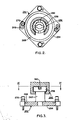
- the bail 241 (Figs. 2, 3) includes a plate 254, of generally rectangular shape with the corners truncated from which an annular lifting knob 256 extends coaxially with the plate.
- the knob 256 is welded to plate 254.
- the head 258 of the knob has key slots 262.
- a 60° conical surface 264 extends inwardly (downwardly) from the inner surface of the top of the head terminating in a slot 266 adapted to receive the male member (not shown) of a bayonette joint which serves to secure the LGT 113 during its transfer by a crane (not shown) from the upper internals (not shown) of the reactor to the clamp-and-index tool 211.
- the plate 254 has an annular finished surface 268.
- the bail 241 is secured to the upper flange 113 of the L GT by bolts 270.
- the upper level 259 is mounted on generally inverted boot-shaped brackets 271 each having a flange 272 secured to the slotted plate just inwardly of the end of the slot.
- the upper level includes tracks 273.
- a slider 27 5 is moveable on pillow blocks 277 along the tracks 273 by a linkage 279.
- the slider carries a box-like structure 281 within which are mounted the mechanism 283 shown in Figs. (6-9) but not in Fig. 1 for raising and rotating the LG T 113.
- the linkage 279 is driven by a rotary hydraulic cylinder (ROTAC) 285 mounted on a plate 287 joined to the boot-shaped brackets 271.
- ROTAC rotary hydraulic cylinder
- the linkage 279 includes a bifurcated crank (Flider crank) or clevis 289, connected to the rotating pin 290 of the cylinder 287. At its bifurcated end, the crank 289 is pivotally connected, through a clevis pin 292, to a link 291 or lever which at its other end is pivotally connected, through a clevis pin 294, to a U-bracket 293 secured to the vertical wall 294 (Fig. 6) of the box-like structure centrally of the plate 295 of the slider 275 from which the box-like structure 281 is suspended.
- the pin of the rotary cylinder 285 rotates between an angular position in which the link 291 is extended, and in which a stop 296 is engaged, and a position in which the link 291 is retracted.
- the box-like structure 281 In the extended position of link 291, the box-like structure 281 is positioned towards the outer end of the slotted plate 261.
- an LGT on pins 265 may be connected to a yoke 295 (Fig. 6) at the lower end of the mechanism 283.
- the yoke 295 may be coupled to the knob 256 of the bail 241 (Fig. 3).
- Fig. 1 shows the linkage in an intermediate position.
- Limit switches are provided for signalling when the slider 275 is in its extreme positions. These switches are provided on a pair of Z-brackets (not shown) mounted on the plate 287 on each side laterally of the rotary cylinder 285. The Z-brackets are centered on the central plane perpendicular to the tracks 273 through the pin 286. Each Z-bracket has a recess on its upper horizontal arm in each of which a magnetizeable member is disposed. A magnetic member is carried by the bifurcated head of the crank 289. The members form proximity switches with the magnet.
- Vertical plates 309 are connected to the inner ends of the boot bracket 281. These plates serve to mount the clamp-and-index tool on the strong-back which supports the robotic tools used in the replacement of the split-pin assemblies.
- the mechanism 283 for raising or lowering and rotating the LGT 113 includes a lift hydraulic cylinder 311 mounted on the plate 295 of the slider 275 which is also the top of the box-like structure 281 (Figs. 1, 4, 5).
- the piston 313 of cylinder 311 is connected to a connecting hub 315 from which a rotary hydraulic cylinder 317 is suspended.
- the cylinder 317 is slideable upwardly or downwardly by the lift cylinder 311.
- the cylinder 317 carries a slide 319 which rides in slots in strips 320 at both ends of the slide 319 (Figs. 7).
- the slide 319 is composed of non-magnetic material such as brass.
- the shaft 3 21 of the rotary cylinder 317 is splined.
- the shaft 321 passes through a top mounting flange 323 which forms the top of a housing 325 with bottom flange 326.
- the shaft 321 is connected to a splined hub 327 of generally longitudinal section which is bolted to a flange or plate 329.
- the plate 329 has a recess in which it carries an extension shaft 331.
- a cap screw 333 is secured to the extension shaft 331. This screw 333 connects the yoke 295 on which the LGT 113 is mounted to the extension shaft 331 through the cap 334.
- the rotatable race 335 of thrust ball bearing 3 36 is secured to the plate 329.
- the fixed race 339 is in the baseplate 341 of housing 325.
- the bearing 336 and not the cap screw 333, carries the weight of the yoke 295 and the members connected to it.
- a metallic (stainless steel) block 343 is bolted to the stem 345 of hub 329.
- a like metallic block 347 is bolted to plate 329, angularly oppositely (180° from) the block 343.
- Conductors 349 and 351 are suspended by bolts at the levels of block 343 and 347, respectively, and both are displaced angularly by 180° from block 343.
- the blocks 343 and 347 are rotatable with the shaft 321.
- the pairs of block and conductor 343-349 and 347-351 operate as proximity limit switches, in the 180° position of the LGT and in the 0° position of the LGT (see Calfo).
- each block 343 or 347 approaches its conductor 349 or 351, it induces eddy currents in its conductor signalling the change in angular position.
- a stop block 353 and cooperative stops, 355 and 357 are provided for limiting the angle of rotary movement of the LGT to 180° (Figs. 6, 8).
- Rollers 359 (Figs. 5, 6) are journalled on pins at the lower end of the box-like structure 281. These rollers ride on the finished annulus 268 (Fig.
- the cap 334 carries a key 360 which engages the keyways 262 in the knob 256 of the bail 241 (Fig. 3).
- Calfo magnetically-actuable reed switches are suspended from the side wall 294 of the box-like structure 281 at the upper and lower limiting positions of the support which carries the rotary cylinder 317.
- the distance between these upper and lower positions is the distance over which the LGT may be raised or lowered. Typically this distance is 4.88 inches.
- the linkage 279 is retracted and the lift cylinder 311 suspends the yoke 295 in the raised position above pins 267 as shown on the left in Fig. 5 (except that in Fig. 5 the LGT 113 is connected to the yoke).
- the lift cylinder 311 lowers the yoke 295 so that it is at the proper level to engage the knob 256 in bail 241. That the yoke is in proper position is determined by actuation of a limit switch (see Calfo).
- the linkage 279 is then actuated to move the slide 275 and the depending yoke 295 to the extended position (to the right as seen in Fig. 5) where the yoke 295 engages the knob 256 and the key 360 engages keyway 262.
- Yoke 295 moves between pins 267 and 265 because it is of smaller width than the distance between the pins.
- linkage 279 is retracted and, when the slide 275 is in the fully retracted position, the yoke and LGT is lowered so that the pins 267 pass through the holes in flange 123 and the holes 269 in the bail 241 and the rollers 359 engaging finished annulus 267.
- the yoke 295 and LGT are raised and the rotary cylinder 317 (Fig. 6) is actuated. During rotation the rollers 359. ride on the finished annulus so that friction against rotation is minimized.
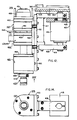
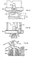
- the lower deck or lower-level member 255 (Figs. 10, 11) includes a clamp assembly 373 for securing the LGT 113 and a pin-puller and expellor 375.
- the clamp assembly 373 includes a bottom plate 376 and a top plate 377.
- the top plate 377 is dowelled by dowel pins 374 (Fig. 11) to the plate 393 which forms part of the assembly that supports pipe 251.
- the bottom plate 376 is bolted to the top plate.
- the outer end of plate 393 defines a VEE to receive the flange 125 of an LGT.
- Columns 380, backed up by plates 382 extend vertically on each side of the VEE.
- a jaw 381 on an arm 383 which passes between top and bottom plates 376 and 377 and terminates in a slotted end 384 (Fig. 11).
- the arm 383 is moveable between plates 376 and 377 and is slideable along rails 386 and 388 bolted and dowelled to the bottom plate 376.
- a cam 385 passes through the slot.
- the slot is shaped to permit the passage of the cam.
- the cam 385 is connected at its upper end to the piston rod 387 of a hydraulic cylinder 389 within pipe 251.
- the jaw 381 of the clamp moves towards the VEE, clamping an LGT flange 125 between the VEE and the jaw, and when the piston rod is moved upwardly from the position shown in Fig. 11, the jaw moves away from the VEE releasing the LGT.
- the position of the cam followers 391 in the clamping setting is shown in full lines in Fig. 11 and in the unclamped position in broken lines.
- An annulus 392 truncated at one end, is secured to the pipe 251 at its lower end (Figs. 10, 11).
- the annulus 392 is bolted to plate 393 which is in turn dowelled to top plate 377.
- the plate 393 has a hole, centered on its longitudinal axis, affording clearance for the elbow of the cam 385.
- the cylinder 389 is mounted on a pedestal 394 on legs 395 on a plate 397 within pipe 251. This plate 397 is bolted to plate 393.
- the plate 397 has a rectangular hole within which the long straight section 399 of the cam 385 is a sliding fit. The cam 385 is guided and supported by plate 397.
- the sensors for sensing the status of the LGT clamp 373 are omitted in the interest of clarity from Figs. 11 and 12.
- Magnetically actuable reed switches are mounted on a bracket bolted to plate 397.
- a magnet is carried at the upper end of the straight section 399 of cam 385. In the uppermost position of the cam 385, in which position the LGT is clamped, the magnet actuates a switch. In the lowermost position of the cam, in which the clamping jaw 381 is retracted, the magnet 403 actuates another switch (see-Calfo).
- the pin-puller and expellor 375 is supported, with its long dimension vertically from an angle bracket 407 (Fig. 12) suspended from a plate 406 bolted to plate 393.
- a rotary hydraulic cylinder 415 is suspended from bracket 407.
- the cylinder 415 swings a generally U-shaped or yoke-shaped bracket 416.
- the bracket 416 has a vertical member 417 to which the upper horizontal member 418 is welded.
- the lower horizontal member 419 is bolted to the vertical member.
- the shaft 420 of the cylinder is clamped to the horizontal members 418 and 419 (Figs. 12-14).
- the vertical member 417 carries a plate 421. Guide bars 422 are bolted to the plate 421.
- the pin-puller and expellor 375 is supported from this plate 421. A part of the pin-puller and expellor is moveable along the plate 421. For this purpose vertically aligned slide 424 slideable in guide bars 422 is connected to the pin-puller and expellor.
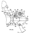
- the bracket 416 and the pin-puller and expellor 375 are supported and are rotatable in thrust bearings 426 mounted in bracket 407. The moveable race of the bearing 426 is connected to horizontal member 418 and the fixed race to bracket 407. As the shaft 420 rotates, it carries the bracket 416 and the pin-puller and expellor 375 with it between an "in" position, 428 (Fig.
- the pin-puller and expellor in which the pin-puller and expellor is centered under the pin to be extracted and may be operated to extract the pin, and an "out" position 430 in which the pin-puller and expellor can discharge an extracted pin into the trash chute 413 (Fig. 19).
- the horizontal sides 418 and 419 of the bracket 407 are sometimes designated as the "radial locator arm" (e.g., see Fig. 94A, Calfo).
- the pin-puller and expellor 375 includes a plurality of hydraulic cylinders 423, 425 and 427 (Fig. 13).
- the cylinder 423 is keyed to plate 421 by key 432 so that it is not moveable vertically.
- the pistons 429, 431 and 433, respectively, of the cylinders are connected to a shaft or actuator 435.
- Another hydraulic cylinder 437 is connected to the lower end of the actuator 435.
- the piston rod 439 of cylinder 437 is connected to the expellor 441, which is slideable within the actuator, and secured by a spring pin 442.
- a collar 443 is threaded onto, and secured to, the actuator 435 just inwardly of the cylinder 437.
- the collar 443 is abutted axially by a spacer 445 between the collar and the piston 429 of cylinder 423. There are also spacers 447 and 449 between the piston 429 and the piston 431 and between the piston 431 and piston 433.
- the actuator 435 Near its upper end, the actuator 435 carries a collet whose jaws 451 are urged outwardly by a spring ring 453 disposed in a slot near the tip of the actuator.
- a flanged annular cam 455 is mounted by its flange 456 on the end cap 457 of cylinder 427. The outer surfaces of the jaws 451 of the collet engage the cam internally. These surfaces are vertically tapered so that when the cam 455 is moved downwardly the collet is closed.
- Pins 458 are supported on the top of cylinder 425. The pins 457 pass through and are slideable in the end cap 459 of cylinder 425, cylinder 427 and its end caps 461 and 463 and the flange
- a bracket 465 (Fig. 12) is mounted on cylinder 427.
- a limit switch L3SW6 is mounted on cylinder 425 just below bracket 465. When cylinder 427 is moved downwardly with respect to 425 to its lowermost position, switch L3SW6 is actuated. In the relative up position of cylinder 427, the cylinders 427 and 425 are separated so that switch L3SW6 is unactuated.
- pin-puller and expellor 375 is swung on bracket 407 and support 417 to the "in" position 428 (Fig. 10) under the pin 127a (Fig. 17) to be replaced. Fluid is supplied under piston 429 of cylinder 423 to raise this piston to its uppermost position. Cylinder 423 remains fixed because it is keyed to plate 421 but actuator 435 and the parts connected to it, including cylinders 437, 425, 427, jaws 451, cam 455, and pins 451 are raised to a position in which the jaws 451 encircle shank 139 of pin 127a just below the flange 143 (Fig. 17). At this point bracket 465 is in the full-line position (Fig. 12) where switch L3SW6 is unactuated.
- a switch is mounted on a clamp secured to the top of cylinder 437 (shown in Calfo but not in Fig. 12).
- this switch is retracted from the end cap 469 of cylinder 423.
- this switch is near the end cap (.10 inch typically) and the switch is actuated indicating that the jaws 451 are near the pin 127 to be replaced.
- the operating personnel can determine whether or not there is a pin 127a in an LGT 113 either by direct vision or by closed TV. There are also occasions when it is known that the pin is not present. If no pin is seen or it is known that no pin is present, the expellor 441 is raised after piston 429 raises the pin-puller and expellor to the position just under the part of the LGT where the pin had been. The expellor is tapered at the tip and enters the hole (480, Fig. 5, Calfo) in the flange 125 in which the pin 127a was lodged to center the LGT. During a replacement operation an LGT is rotated several times through 180° so that it is positioned properly for the action of each tool in its turn. On each occasion the LGT is centered by the expellor.
- the pin 127a to be replaced is severed by an electric arc produced by the MDM (Calfo).
- the severence is effected by the electric arc between the nut 145 (Fig. 17) and a graphite electrode and continues until the shank 139 of the pin 127a is penetrated.
- the internal thread of the nut 145 begins a short distance (typically .040 inch) above its bottom.
- the nut is penetrated in this region by the electric arc so that the pin fragment 471 free of the nut is released to be disposed in the trash chute 413.
- the arc potential is between the electrode 229 which is electrically "hot” and the pin 127a which is grounded through the pin-puller and expellor 375. (See Fig. 12 where the cam 455 is shown grounded.)
Landscapes
- Engineering & Computer Science (AREA)
- Mechanical Engineering (AREA)
- Robotics (AREA)
- Manipulator (AREA)
- Automatic Assembly (AREA)
- Load-Engaging Elements For Cranes (AREA)
- Bending Of Plates, Rods, And Pipes (AREA)
- Cutting Tools, Boring Holders, And Turrets (AREA)
Applications Claiming Priority (2)
| Application Number | Priority Date | Filing Date | Title |
|---|---|---|---|
| US617859 | 1984-06-06 | ||
| US06/617,859 US4624042A (en) | 1984-06-06 | 1984-06-06 | Robotic clamp and index tool and method for their use in repairing certain elements with in a nuclear reactor |
Publications (2)
| Publication Number | Publication Date |
|---|---|
| EP0164990A2 true EP0164990A2 (de) | 1985-12-18 |
| EP0164990A3 EP0164990A3 (de) | 1988-05-18 |
Family
ID=24475342
Family Applications (1)
| Application Number | Title | Priority Date | Filing Date |
|---|---|---|---|
| EP85303918A Withdrawn EP0164990A3 (de) | 1984-06-06 | 1985-06-04 | Automatische Spann- und Indexiervorrichtung |
Country Status (5)
| Country | Link |
|---|---|
| US (1) | US4624042A (de) |
| EP (1) | EP0164990A3 (de) |
| JP (1) | JPS613089A (de) |
| KR (1) | KR860000129A (de) |
| ES (1) | ES8706283A1 (de) |
Cited By (3)
| Publication number | Priority date | Publication date | Assignee | Title |
|---|---|---|---|---|
| FR2840722A1 (fr) * | 2002-06-11 | 2003-12-12 | Framatome Anp | Procede et dispositif de reconstitution d'un element de positionnement d'un assemblage de combustible sur une plaque de support de coeur d'un reacteur nucleaire |
| FR2841367A1 (fr) * | 2002-06-11 | 2003-12-26 | Framatome Anp | Dispositif de positionnement et d'alignement axial d'un assemblage de combustible et procede et dispositif de reconstitution d'un element de positionnement |
| CN114393395A (zh) * | 2022-03-11 | 2022-04-26 | 宁波公牛电器有限公司 | 组装设备及装配方法 |
Families Citing this family (10)
| Publication number | Priority date | Publication date | Assignee | Title |
|---|---|---|---|---|
| US4756067A (en) * | 1986-07-31 | 1988-07-12 | Westinghouse Electric Corp. | Manual replacement of old split-pin assemblies by new split-pin assemblies |
| US4748733A (en) * | 1986-08-29 | 1988-06-07 | Westinghouse Electric Corp. | Removal of old split-pin assemblies from guide tubes and replacement by new split-pin assemblies |
| US4791801A (en) * | 1987-08-03 | 1988-12-20 | Westinghouse Electric Corp. | Reversible fuel assembly grid tab repair tool |
| US4824632A (en) * | 1987-12-31 | 1989-04-25 | Westinghouse Electric Corp. | Fuel assembly alignment pin straightening device |
| US5042861A (en) * | 1989-06-13 | 1991-08-27 | Tennessee Valley Authority | Nozzle dam remote installation system and technique |
| US5249209A (en) * | 1989-07-07 | 1993-09-28 | Westinghouse Electric Corp. | Control rod canopy seal positioning and welding system |
| US5265667A (en) * | 1989-09-14 | 1993-11-30 | Westinghouse Electric Corp. | Robotic arm for servicing nuclear steam generators |
| US8720498B2 (en) * | 2007-07-16 | 2014-05-13 | Energysolutions, Llc | Remote fill head with automatic drip tray |
| JP5730156B2 (ja) * | 2011-08-12 | 2015-06-03 | 三菱重工業株式会社 | 制御棒クラスタ案内管の支持ピン交換装置 |
| CN113927279B (zh) * | 2021-09-29 | 2023-03-10 | 浙江科腾精工机械股份有限公司 | 一种螺栓与垫片自动套接装配设备 |
Family Cites Families (6)
| Publication number | Priority date | Publication date | Assignee | Title |
|---|---|---|---|---|
| DE2756370A1 (de) * | 1977-12-17 | 1979-06-21 | Noell Gmbh | Kombinierter greifer in einem kernreaktor |
| ES465585A1 (es) * | 1977-12-31 | 1978-09-16 | Science Union & Cie | Procedimiento de preparacion de nuevas piperazinas disusti- tuidas. |
| WO1980000672A1 (en) * | 1978-10-03 | 1980-04-17 | Pilgrim Eng Dev | Stud manipulating device |
| JPS5848896A (ja) * | 1981-09-18 | 1983-03-22 | 有限会社郷鋳造鉄工所 | 核燃料集合体に対するチヤンネルボツクスの套嵌姿勢自動修正装置 |
| US4482520A (en) * | 1982-01-08 | 1984-11-13 | Maine Yankee Atomic Power Company | Fuel pin transfer tool |
| FR2531563A1 (fr) * | 1982-08-06 | 1984-02-10 | Framatome Sa | Procede de remplacement des broches de guidage d'un tube-guide faisant partie des equipements internes superieurs d'un reacteur nucleaire a eau sous pression et dispositif correspondant |
-
1984
- 1984-06-06 US US06/617,859 patent/US4624042A/en not_active Expired - Lifetime
-
1985
- 1985-05-31 JP JP60119654A patent/JPS613089A/ja active Pending
- 1985-06-01 KR KR1019850003840A patent/KR860000129A/ko not_active Withdrawn
- 1985-06-04 EP EP85303918A patent/EP0164990A3/de not_active Withdrawn
- 1985-06-04 ES ES543883A patent/ES8706283A1/es not_active Expired
Cited By (6)
| Publication number | Priority date | Publication date | Assignee | Title |
|---|---|---|---|---|
| FR2840722A1 (fr) * | 2002-06-11 | 2003-12-12 | Framatome Anp | Procede et dispositif de reconstitution d'un element de positionnement d'un assemblage de combustible sur une plaque de support de coeur d'un reacteur nucleaire |
| FR2841367A1 (fr) * | 2002-06-11 | 2003-12-26 | Framatome Anp | Dispositif de positionnement et d'alignement axial d'un assemblage de combustible et procede et dispositif de reconstitution d'un element de positionnement |
| US6888912B2 (en) | 2002-06-11 | 2005-05-03 | Framatome Anp | Device for positioning and axially aligning a fuel assembly and process and apparatus for restoring a positioning element |
| US6980620B2 (en) | 2002-06-11 | 2005-12-27 | Framatome Anp | Device for positioning and axially aligning a fuel assembly and process and apparatus for restoring a positioning element |
| CN114393395A (zh) * | 2022-03-11 | 2022-04-26 | 宁波公牛电器有限公司 | 组装设备及装配方法 |
| CN114393395B (zh) * | 2022-03-11 | 2023-07-25 | 宁波公牛电器有限公司 | 组装设备及装配方法 |
Also Published As
| Publication number | Publication date |
|---|---|
| KR860000129A (ko) | 1986-01-25 |
| US4624042A (en) | 1986-11-25 |
| EP0164990A3 (de) | 1988-05-18 |
| JPS613089A (ja) | 1986-01-09 |
| ES8706283A1 (es) | 1987-06-01 |
| ES543883A0 (es) | 1987-06-01 |
Similar Documents
| Publication | Publication Date | Title |
|---|---|---|
| US4624042A (en) | Robotic clamp and index tool and method for their use in repairing certain elements with in a nuclear reactor | |
| US5711382A (en) | Automated oil rig servicing system | |
| US3266582A (en) | Drilling system | |
| US5988299A (en) | Automated oil rig servicing system | |
| US5259723A (en) | Feeding device for down hole tubulars | |
| JPH037276B2 (de) | ||
| CN101239437A (zh) | 细长销水平自动装配装置 | |
| CN110000854A (zh) | 一种管材智能钻孔控制系统及控制方式 | |
| EP0140586A2 (de) | Anbringen von Muffen an Rohren in aggrssiven Umgebungen | |
| CN210977348U (zh) | 一种石油修井用自动化上卸扣装置 | |
| CN102102496B (zh) | 油田作业中落鱼磨铣实验夹持扶正装置 | |
| CN108723395A (zh) | 一种圆柱棒料自动倒角装置 | |
| EP0299539B1 (de) | Vorrichtung zum Einbringen von Hülsen in die Beschädigten Rohre eines nuklearen Dampfgenerators | |
| CN105590717B (zh) | 继电器自动充磁机 | |
| DE2753161A1 (de) | Verfahren und vorrichtung zum wechseln von mess- und/oder probennahmesonden fuer stahlschmelzen | |
| US2570308A (en) | Automatic chuck for pulldown devices | |
| US4756067A (en) | Manual replacement of old split-pin assemblies by new split-pin assemblies | |
| CN105269230B (zh) | 用于叉车内门架上横梁的铆焊工装 | |
| CN1106649C (zh) | 核电站反应堆测温热电偶插装机械手 | |
| CN218193338U (zh) | 一种灵活自调式液压缸焊接滚轮架 | |
| EP0164991A2 (de) | Metaldesintegrierungsanordnung | |
| DE3115514A1 (de) | Vorrichtung zum annippeln von aktiven elektrodenabschnitten an eine kombinationselektrode | |
| CN206185514U (zh) | 一种环抱式定位夹紧机构 | |
| EP0594381B1 (de) | Wartungsausrüstung für einen Kontrollstab | |
| CN206356821U (zh) | 一种具有机械手臂的自动焊接平台 |
Legal Events
| Date | Code | Title | Description |
|---|---|---|---|
| PUAI | Public reference made under article 153(3) epc to a published international application that has entered the european phase |
Free format text: ORIGINAL CODE: 0009012 |
|
| AK | Designated contracting states |
Designated state(s): BE FR GB IT SE |
|
| PUAL | Search report despatched |
Free format text: ORIGINAL CODE: 0009013 |
|
| AK | Designated contracting states |
Kind code of ref document: A3 Designated state(s): BE FR GB IT SE |
|
| STAA | Information on the status of an ep patent application or granted ep patent |
Free format text: STATUS: THE APPLICATION IS DEEMED TO BE WITHDRAWN |
|
| 18D | Application deemed to be withdrawn |
Effective date: 19890102 |
|
| RIN1 | Information on inventor provided before grant (corrected) |
Inventor name: GREEN, RICHARD ALEXANDER |