EP0165038A2 - Eine Steueranlage zur selektiven Elektrizitätsversorgung - Google Patents
Eine Steueranlage zur selektiven Elektrizitätsversorgung Download PDFInfo
- Publication number
- EP0165038A2 EP0165038A2 EP85304103A EP85304103A EP0165038A2 EP 0165038 A2 EP0165038 A2 EP 0165038A2 EP 85304103 A EP85304103 A EP 85304103A EP 85304103 A EP85304103 A EP 85304103A EP 0165038 A2 EP0165038 A2 EP 0165038A2
- Authority
- EP
- European Patent Office
- Prior art keywords
- cylinder
- contacts
- enclosure
- electricity
- chamber
- Prior art date
- Legal status (The legal status is an assumption and is not a legal conclusion. Google has not performed a legal analysis and makes no representation as to the accuracy of the status listed.)
- Granted
Links
Images


Classifications
-
- B—PERFORMING OPERATIONS; TRANSPORTING
- B60—VEHICLES IN GENERAL
- B60H—ARRANGEMENTS OF HEATING, COOLING, VENTILATING OR OTHER AIR-TREATING DEVICES SPECIALLY ADAPTED FOR PASSENGER OR GOODS SPACES OF VEHICLES
- B60H1/00—Heating, cooling or ventilating devices
- B60H1/32—Cooling devices
- B60H1/3204—Cooling devices using compression
- B60H1/3205—Control means therefor
- B60H1/3208—Vehicle drive related control of the compressor drive means, e.g. for fuel saving purposes
Definitions
- the present invention relates to a control apparatus for supplying electricity to an air conditioning control device for a vehicle which includes a compressor driven by an engine. More particularly, the present invention relates to improvements on an apparatus for supplying electricity to a relay of the compressor of the air conditioning control device at an initiation of acceleration of the vehicle. As a result, electricity is not supplied to the compressor, and almost all the output from the engine is used to drive the vehicle at full speed.
- Automobile air conditioning systems are commonly driven through a mechanical connection to the vehicle engine.
- operation of the air conditioning system when maximum engine output is needed may add an excessive load to the engine.
- a control apparatus is necessary to disconnect the connection between the engine and air conditioning system when the engine accelerates.
- a control apparatus is disclosed in Japanese Utility Model Application Laid-open No. Showa 52-132548.
- This Laid-open Application No. Showa 52-132548 discloses a vacuum manipulator as an apparatus for cutting off electricity, which manipulator communicates with an intake manifold of the engine. When the vehicle is accelerating at full speed, a vacuum of the intake manifold becomes weak. As a result, the vacuum manipulator cuts off electricity to a compressor of the air conditioning control device, and almost all the output from the engine is used to drive the vehicle at full speed.
- the vacuum manipulator cannot be useful as the apparatus for cutting off electricity to the compressor of the air conditioning control device installed on a diesel engine, because the diesel engine has a constant vacuum in an intake manifold thereof.
- the Laid-open Application No. Showa 52-132548 discloses delay mechanisms for maintaining the condition that electricity is not supplied to the compressor of the air conditioning control device during a predetermined period after the vacuum manipulator cuts off the electricity.
- One of the delay mechanisms includes a vacuum reservoir and an orifice, and an another delay mechanism includes a delay relay.
- the use of a vacuum manipulator and delay mechanisms result in a relatively large, bulky device for interrupting the supply of electricity.
- a compact apparatus which includes both the apparatus for cutting of electricity and delay mechanisms is not disclosed.
- U.S. Patent No. 3,186,184 discloses an air conditioning control apparatus which is directly responsive to the displacement of an accelerator pedal.
- the air conditioning control apparatus frequently cuts off electricity, according to the displacement of the accelerator pedal. This necessitates a higher durability of this apparatus, and a higher manufacturing cost.
- the air conditioning control apparatus maintains a condition that the electricity is not supplied to a compressor. Accordingly, a passenger cannot obtain cool air during the accelerating, condition of the vehicle.
- the present invention was developed in view of the foregoing background and to overcome the foregoing drawbacks. It is accordingly an object of this invention to provide an apparatus for supplying electricity to a relay of a compressor of an air conditioning control device which can be utilized for both a gasoline engine and a diesel engine.
- a rod is provided in the apparatus for supplying electricity, which rod is projected from an intermediate cylinder of the apparatus.
- the rod is operated when an accelerator pedal of a vehicle is operated by a driver, or when a throttle valve of an engine is opened.
- the intermediate cylinder includes a check valve which is mounted on a bottom portion thereof, and a pair of contacts which are positioned on an inner top surface thereof.
- the intermediate cylinder is slidably mounted on an inner cylindrical surface of an outer cylinder, and each of the contacts is respectively electrically connected to a pair of terminals which are mounted on an outer surface of the outer cylinder.
- the outer cylinder includes an orifice mounted on a bottom portion thereof.
- an inner cylinder is slidably mounted on an inner cylindrical surface of the intermediate cylinder, and the inner cylinder includes an air passage and an another contact.
- the air passage connects a lower chamber defined between an inner bottom surface of the intermediate cylinder and an outer bottom surface of the inner cylinder to an upper chamber defined between the inner top surface of the intermediate cylinder and an outer top surface of the inner cylinder.
- Another orifice is formed on the air passage of the inner cylinder, and the another contact is mounted on the outer top surface of the inner cylinder.
- a bias spring is mounted between an outer bottom surface of the intermediate cylinder and an inner bottom surface of the outer cylinder, and the intermediate cylinder is biased in the direction which separates it from the inner bottom surface of the outer cylinder.
- Another bias spring is mounted between the inner top surface of the intermediate cylinder and the outer top surface of the inner cylinder, and the inner cylinder is biased in the direction which separates it from the inner top surface of the inner intermediate cylinder.
- the apparatus for supplying electricity includes the inner cylinder and the intermediate cylinder within the outer cylinder.
- the apparatus is compact.
- the apparatus is operated by the rod of the intermediate cylinder which rod is responsive to vehicle acceleration. Therefore, this apparatus can be utilized for both the gasoline and diesel engines.
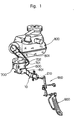
- a compressor 700 of an air conditioning control device is mounted on a vehicle floor, and a relay 600 is mounted on the compressor 700.
- the relay 600 normally closes a circuit 610, and supplies electricity from a battery 500 to the compressor 700, as shown in Figure 2.
- the compressor 700 includes a driven pulley 701 and a clutch (not shown in drawings), and the driven pulley 701 of the compressor 700 is connected to an engine 800 by a belt 801.
- the clutch of the compressor 700 is coupled to a driven shaft 702 on which the driven pulley 701 is mounted.
- the compressor 700 is driven by the engine 800 and actuates an air conditioning control device so that cool air is supplied to a compartment of the vehicle.
- the relay 600 is connected to a control apparatus 10 for supplying the electricity to the relay 600 of the compressor 700 by a pair of connecting wires 601.
- the apparatus 10 includes a rod 210 connected to an accelerator pedal 900 by a link mechanism 950. Accordingly, when the accelerator pedal 900 is displaced by an operator in order to accelerate the vehicle, the rod 210 of the apparatus 10 is displaced within the apparatus 10.
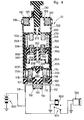
- the apparatus 10 includes three enclosures, preferably an outer cylinder 100, an intermediate cylinder 200 and an inner cylinder 300.
- the inner cylinder 300 is slidably mounted on an inner cylindrical surface 202 of the intermediate cylinder 200.
- An outer diameter of the inner cylinder 300 is slightly shorter than an inner diameter of the intermediate cylinder 200, and grease adheres on the inner cylindrical surface 202 of the intermediate cylinder 200 and an outer cylindrical surface 302 of the inner cylinder 300. Accordingly, the inner cylinder 300 slides smoothly within the intermediate cylinder 200, but a seal is provided therebetween so that there is no air passage between the outer cylindrical surface 302 of the inner cylinder 300 and the inner cylindrical surface 202 of the intermediate cylinder 200.
- the intermediate cylinder 200 is slidably mounted on an inner cylindrical surface 102 of the outer cylinder 100.
- An outer diameter of the intermediate cylinder 200 is slightly shorter than an inner diameter of the outer cylinder 100, and grease adheres on the inner cylindrical surface 102 of the outer cylinder 100 and an outer cylindrical surface 203 of the intermediate cylinder 200. Accordingly, the intermediate cylinder 200 slides smoothly within the outer cylinder 100, but a seal is provided therebetween so that there is no air passage between the outer cylindrical surface 203 of the intermediate cylinder 200.
- the outer cylinder 100 includes a pair of terminals 112,. 116 and a bottom air passage 150 on a bottom portion thereof.
- the terminals 112, 116 project from an outer bottom surface 104 of the outer cylinder 100.
- the terminal 112 is connected to a movable contact 114 by a flexible connecting wire 113, and the movable contact 114 is positioned within the outer cylinder 100 but separated from an inner bottom surface 106 of the outer cylinder 100 by a bottom coil spring 160.
- the terminal 116 is connected to an another movable contact 118 by an another flexible connecting wire 117, and the movable contact 118 is positioned within the outer cylinder 100 but separated from the inner bottom surface 106 by an another bottom coil spring 160.
- the bottom air passage 150 is opened preferably at a central portion of a bottom plate 105, and an air filter 140 is positioned on a lower portion of the air passage 150.
- a bottom orifice 152 is defined on an upper portion of the air passage 150.
- a lower bias spring 170 is mounted on the inner bottom surface 106 of the outer cylinder 100, and the intermediate cylinder 200 is biased upwardly by the lower bias spring 170. Accordingly, a bottom chamber 180 is defined between the inner bottom surface 106 and the inner cylindrical surface 102 of the outer cylinder 100 and an outer bottom surface 204 of the intermediate cylinder 200.
- the outer cylinder 100 includes a top hole 124, an upper wall 108, a plurality of upper air passages 126 and a top chamber 120.
- the top hole 124 is opened preferably at a central portion of an inner top surface 122, and the rod 210 of the apparatus 10 is inserted into the top hole 124.
- An 0-ring 128 is positioned between the rod 210 and the top hole 124, so that the top chamber 120 cannot communicate with the outside of the outer cylinder 100 through the top hole 124.
- a plurality of upper air passages 126 are defined between the inner top surface 122 and the upper wall 108, and a plurality of air filters 140 are positioned on the corresponding plurality of the upper air passages 126. Accordingly, the top chamber 120 is defined among the inner top surface 122 of the outer cylinder 100, a plurality of the air filters 140 and an outer top surface 207 of the intermediate cylinder 200.
- the rod 210 projects from a central portion of the outer top surface 207 of the intermediate cylinder 200, and a top air passage 212 is defined within the rod 210.
- An upper chamber 280 of the intermediate cylinder 200 communicates with the top chamber 120 of the outer cylinder 100 through the top air passage 212.
- the intermediate cylinder 200 includes a check valve 220 and a pair of outer bottom contacts 252, 255 on a bottom portion thereof.
- the check valve 220 includes a lip 222 and a base 224 thereon.
- a plurality of air passages 226 are opened in an inner bottom plate 208.
- the base 224 of the check valve 220 is fixed at a central portion of the inner bottom plate 208, and the lip 222 covers a plurality of the air passages 226 and a part of the inner bottom surface 205 of the intermediate cylinder 200. Accordingly, the lip 222 of the check valve 220 normally prevents the bottom chamber 180 of the outer cylinder 100 from communicating with a lower chamber 290 of the intermediate cylinder 200.
- the pair of the outer bottom contacts 252, 255- project downwardly from the outer bottom surface 204 of the intermediate cylinder 200.
- a pair of inner top contacts 251, 254 project downwardly from the inner top surface 206 of the intermediate cylinder 200, and are respectively connected to the pair of the outer bottom contacts 252, 255 through a pair of connecting wires 253, 256.
- an upper bias spring 270 is positioned between the inner top surface 206 of the intermediate cylinder 200 and an outer top surface 308 of the inner cylinder 300, and the inner cylinder 300 is biased downwardly.
- the inner cylinder 300 tends to separate from the inner top surface 206 of the intermediate cylinder 200 by the upper bias spring 270, and the upper chamber 280 is defined among the inner top surface 206, the inner cylindrical surface 202 of the intermediate cylinder 200 and the outer top surface 308 of the inner cylinder 300.
- the inner cylinder 300 includes a recess 306 on the outer bottom surface 304 thereof, and the lower chamber 290 is defined between the recess 306 of the inner cylinder 300 and the inner bottom surface 205 of the intermediate cylinder 200.
- the inner cylinder 300 includes an intermediate air passage 310 and a connector 350 thereon.
- An orifice 312 is defined within the intermediate air passage 310 of the inner cylinder 300.
- a pair of movable contacts 352, 356 are respectively positioned on the outer top surface 308 of the inner cylinder 300, and are respectively supported over the connector 350 by a pair of upper coil springs 360.
- a pair of flexible connecting wires 354, 358 connect respectively the movable contacts 352, 356 to the connector 350.
- control apparatus 10 for supplying the electricity to the relay 600 of the compressor 700 of the air conditioning control device is disclosed hereinafter.
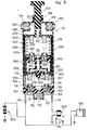
- Figure 2 shows components of the apparatus 10 in a condition when the vehicle is normally driving.
- the intermediate cylinder 200 is biased upwardly by the lower bias spring 170, and the outer top surface 207 of the intermediate cylinder 200 abuts on the upper wall 108 of the outer cylinder 100.
- the inner cylinder 300 is biased downwardly by the upper bias spring 270, and the outer bottom surface 304 of the inner cylinder 300 abuts on the inner bottom surface 205 of the intermediate cylinder 200.
- the rod 210 of the intermediate cylinder 200 is displaced within the outer cylinder 100 as shown in Figure 3.
- the intermediate cylinder 200 is moved downwardly against the bias force of the lower bias spring 170, and the pair of the outer. bottom contacts 252, 255 of the intermediate cylinder 200 are respectively in contact with the pair of movable contacts 114; 118 of the outer cylinder 100.
- the bottom chamber 180 of the outer cylinder 100 becomes smaller, air flows from the bottom chamber 180 of the outer cylinder 100 to the lower chamber 290 of the intermediate cylinder 200 through a plurality of air passages 226.
- the air flowing to the lower chamber 290, of the intermediate cylinder 200 pushes upwardly on the inner cylinder 300 against the bias force of the upper bias spring 270, and the lower chamber 290 of the intermediate cylinder 200 expands.
- the inner cylinder 300 has the intermediate orifice 312 within the intermediate air passage 310 to regulate the amount of the air passing therethrough.
- the air flow is preferably regulated by providing constrictions in the bottom surface 152 and intermediate air passage 310.
- the pair of the movable contacts 352, 356 are respectively in contact with the pair of the inner top contacts 251, 254. Therefore, electricity is supplied from the battery 500 to the relay 600 through the apparatus 10, and the relay 600 opens the circuit 610. As a result, electricity cannot be supplied from the battery 500 to the compressor 700 through the relay 600, and almost all of the output from the engine 800 can be used in order to drive the vehicle.
- the inner cylinder 300 is gradually pushed down by the bias force of the upper bias spring 270 after the condition shown in Figure 3. Electricity is still supplied to the relay and thus not supplied to the compressor for a predetermined time period after initiation of acceleration which time period extends until the pair of movable contacts 352, 356 gradually separates from the pair of the inner top contacts 251, 254 after a predetermined time period.
- the predetermined time period depends on a size of the intermediate orifice 312 of the inner cylinder 300. That is, air from the lower chamber 290 flows to the upper chamber 280 through the intermediate orifice 312, thereby permitting the inner cylinder 300 to move down to disconnect the movable contacts 352, 356 from the top contacts 251, 254.
- the rate of downward movement of the inner cylinder 300 depends on the size of the constriction in the intermediate orifice 312.
- FIG. 6 A second embodiment of an apparatus for supplying electricity to a relay of a compressor of an air conditioning control device is shown in Figure 6.
- the second embodiment is substantially similar to the first embodiment disclosed in Figure 2.
- the major differenee between the apparatus 11 shown in Figure 6 and the apparatus 10 shown in Figure 2 is that a pair of outer bottom contacts 252, 255 of an intermediate cylinder 200 are respectively connected to a pair of terminals 112, 116 of an outer cylinder 100 through a pair of flexible connecting wires 113, 117.
- the present invention overcomes the shortcomings of the known art by providing an compact apparatus which supplies electricity to a relay of a compressor of an air conditioning control device.
Landscapes
- Physics & Mathematics (AREA)
- Thermal Sciences (AREA)
- Engineering & Computer Science (AREA)
- Mechanical Engineering (AREA)
- Air-Conditioning For Vehicles (AREA)
Applications Claiming Priority (2)
| Application Number | Priority Date | Filing Date | Title |
|---|---|---|---|
| JP59120575A JPS611530A (ja) | 1984-06-12 | 1984-06-12 | 自動車用空調装置のク−ラカツト制御器 |
| JP120575/84 | 1984-06-12 |
Publications (3)
| Publication Number | Publication Date |
|---|---|
| EP0165038A2 true EP0165038A2 (de) | 1985-12-18 |
| EP0165038A3 EP0165038A3 (en) | 1986-12-30 |
| EP0165038B1 EP0165038B1 (de) | 1989-03-22 |
Family
ID=14789681
Family Applications (1)
| Application Number | Title | Priority Date | Filing Date |
|---|---|---|---|
| EP85304103A Expired EP0165038B1 (de) | 1984-06-12 | 1985-06-10 | Eine Steueranlage zur selektiven Elektrizitätsversorgung |
Country Status (4)
| Country | Link |
|---|---|
| US (1) | US4596121A (de) |
| EP (1) | EP0165038B1 (de) |
| JP (1) | JPS611530A (de) |
| DE (1) | DE3568962D1 (de) |
Families Citing this family (9)
| Publication number | Priority date | Publication date | Assignee | Title |
|---|---|---|---|---|
| US5694781A (en) * | 1996-08-01 | 1997-12-09 | Smart Power Systems, Inc. | Control algorithm for vehicle air conditioning system with a variable orifice |
| ES2146550B1 (es) * | 1998-11-11 | 2001-03-01 | Gestion Desarrollos Electronic | Interruptor de red para televisor con desconexion degaussing. |
| WO2001080261A1 (es) * | 2000-04-19 | 2001-10-25 | Gestion Desarrollos Electronicos, S.A. | Mejoras introducidas en el objeto de la patente n° 9802346 por interruptor de red para televisor con desconexion degaussing |
| JP4733532B2 (ja) * | 2006-02-01 | 2011-07-27 | 積水化学工業株式会社 | 管継手 |
| US7216495B1 (en) | 2006-03-02 | 2007-05-15 | Harrison Thomas D | Air conditioning system |
| US7308799B1 (en) | 2006-03-02 | 2007-12-18 | Harrison Thomas D | Air conditioning system operating on vehicle waste energy |
| US7260947B1 (en) | 2006-03-02 | 2007-08-28 | Harrison Thomas D | Air conditioning system operating on vehicle waste energy |
| GB2449099A (en) * | 2007-05-09 | 2008-11-12 | Paul Clifford | Vehicle Power Management System |
| US8278867B2 (en) * | 2011-03-03 | 2012-10-02 | General Electric Company | Circuit and method for applying a three phase power source to a three phase load |
Family Cites Families (11)
| Publication number | Priority date | Publication date | Assignee | Title |
|---|---|---|---|---|
| US2746261A (en) * | 1953-10-26 | 1956-05-22 | Gen Motors Corp | Refrigerating apparatus |
| US3186184A (en) * | 1963-12-23 | 1965-06-01 | Portable Equipment Inc | Air conditioning control apparatus |
| US3462964A (en) * | 1967-09-12 | 1969-08-26 | Ralph K Haroldson | Air conditioner control means responsive to vehicle engine power demands |
| GB1344068A (en) * | 1970-09-11 | 1974-01-16 | Smiths Ind | Switches |
| DE2614290A1 (de) * | 1976-04-02 | 1977-10-13 | Volkswagenwerk Ag | Kuehlvorrichtung fuer kraftfahrzeuge |
| US4155225A (en) * | 1977-09-23 | 1979-05-22 | Upchurch Thomas B Jr | Air conditioner control means |
| JPS5686820A (en) * | 1979-12-18 | 1981-07-15 | Nissan Motor Co Ltd | Automatic control device for clutch of car cooler |
| US4269033A (en) * | 1980-01-30 | 1981-05-26 | Birch Robert J | Switching device |
| JPS57130816A (en) * | 1981-02-02 | 1982-08-13 | Hayashi Seikou Kk | Automatic switch for car coolers |
| US4424682A (en) * | 1982-02-16 | 1984-01-10 | General Motors Corporation | Vehicle air conditioning compressor control system |
| US4445341A (en) * | 1982-06-23 | 1984-05-01 | Mikio Hayashi | Automatic switching system for car cooler |
-
1984
- 1984-06-12 JP JP59120575A patent/JPS611530A/ja active Pending
-
1985
- 1985-06-07 US US06/742,542 patent/US4596121A/en not_active Expired - Fee Related
- 1985-06-10 DE DE8585304103T patent/DE3568962D1/de not_active Expired
- 1985-06-10 EP EP85304103A patent/EP0165038B1/de not_active Expired
Also Published As
| Publication number | Publication date |
|---|---|
| US4596121A (en) | 1986-06-24 |
| DE3568962D1 (en) | 1989-04-27 |
| EP0165038B1 (de) | 1989-03-22 |
| EP0165038A3 (en) | 1986-12-30 |
| JPS611530A (ja) | 1986-01-07 |
Similar Documents
| Publication | Publication Date | Title |
|---|---|---|
| US4596121A (en) | Control apparatus for selectively supplying electricity | |
| JPS5933690Y2 (ja) | 自動車用の冷房装置 | |
| US4380418A (en) | Vacuum pressure selection and generation device | |
| US4355523A (en) | Automatic car-cooler clutch control apparatus | |
| US4391242A (en) | Control device for auxiliary members of a vehicle | |
| EP1008483A3 (de) | Regelsystem für ein Hybridfahrzeug | |
| EP0084825A2 (de) | Regelverfahren für Brennkraftmaschine | |
| US4234066A (en) | Dual stage fluid clutch motor with electric controls including time delay | |
| JPH0474553B2 (de) | ||
| US5259349A (en) | Device for the adjustment of a throttle valve | |
| US4269033A (en) | Switching device | |
| US3921751A (en) | Method and apparatus for automatically maintaining the speed of an automobile at a constant preselected value | |
| US2938403A (en) | Control for transmission | |
| US4071006A (en) | Exhaust gas recirculating system | |
| US2648016A (en) | Automatic starter-energizing circuit for automotive vehicles | |
| US2833880A (en) | Stop light control arrangement | |
| US4445341A (en) | Automatic switching system for car cooler | |
| EP0193502B1 (de) | Servo-Reibungskupplungsvorrichtung zum Automatisieren der Kupplungswirkung bei Motorfahrzeugen jeder Art | |
| US4338908A (en) | Oil saver for vehicles | |
| EP0728967A2 (de) | Unterdruckhalteventil | |
| US4111167A (en) | Carburetor by-pass | |
| US4586472A (en) | Arrangement in motor vehicles for indicating engine loads | |
| GB2089895A (en) | Valve control of carburettor idling mixture systems | |
| CA1191127A (en) | Actuator system with electric to pressure transducer | |
| JPS58206842A (ja) | エンジン制御装置 |
Legal Events
| Date | Code | Title | Description |
|---|---|---|---|
| PUAI | Public reference made under article 153(3) epc to a published international application that has entered the european phase |
Free format text: ORIGINAL CODE: 0009012 |
|
| AK | Designated contracting states |
Designated state(s): DE FR GB |
|
| 17P | Request for examination filed |
Effective date: 19860613 |
|
| PUAL | Search report despatched |
Free format text: ORIGINAL CODE: 0009013 |
|
| AK | Designated contracting states |
Kind code of ref document: A3 Designated state(s): DE FR GB |
|
| 17Q | First examination report despatched |
Effective date: 19880108 |
|
| GRAA | (expected) grant |
Free format text: ORIGINAL CODE: 0009210 |
|
| AK | Designated contracting states |
Kind code of ref document: B1 Designated state(s): DE FR GB |
|
| REF | Corresponds to: |
Ref document number: 3568962 Country of ref document: DE Date of ref document: 19890427 |
|
| ET | Fr: translation filed | ||
| PLBE | No opposition filed within time limit |
Free format text: ORIGINAL CODE: 0009261 |
|
| STAA | Information on the status of an ep patent application or granted ep patent |
Free format text: STATUS: NO OPPOSITION FILED WITHIN TIME LIMIT |
|
| 26N | No opposition filed | ||
| PGFP | Annual fee paid to national office [announced via postgrant information from national office to epo] |
Ref country code: GB Payment date: 19910531 Year of fee payment: 7 |
|
| PGFP | Annual fee paid to national office [announced via postgrant information from national office to epo] |
Ref country code: FR Payment date: 19910619 Year of fee payment: 7 |
|
| PGFP | Annual fee paid to national office [announced via postgrant information from national office to epo] |
Ref country code: DE Payment date: 19910628 Year of fee payment: 7 |
|
| PG25 | Lapsed in a contracting state [announced via postgrant information from national office to epo] |
Ref country code: GB Effective date: 19920610 |
|
| GBPC | Gb: european patent ceased through non-payment of renewal fee |
Effective date: 19920610 |
|
| PG25 | Lapsed in a contracting state [announced via postgrant information from national office to epo] |
Ref country code: FR Effective date: 19930226 |
|
| PG25 | Lapsed in a contracting state [announced via postgrant information from national office to epo] |
Ref country code: DE Effective date: 19930302 |
|
| REG | Reference to a national code |
Ref country code: FR Ref legal event code: ST |