EP0165175A2 - Abzug und Lüftungsanlage, regelbar in Abhängigkeit von der Temperatur und dem Feuchtigkeitsgrad des Luftstroms - Google Patents
Abzug und Lüftungsanlage, regelbar in Abhängigkeit von der Temperatur und dem Feuchtigkeitsgrad des Luftstroms Download PDFInfo
- Publication number
- EP0165175A2 EP0165175A2 EP85401129A EP85401129A EP0165175A2 EP 0165175 A2 EP0165175 A2 EP 0165175A2 EP 85401129 A EP85401129 A EP 85401129A EP 85401129 A EP85401129 A EP 85401129A EP 0165175 A2 EP0165175 A2 EP 0165175A2
- Authority
- EP
- European Patent Office
- Prior art keywords
- mouth
- bimetallic strip
- air
- extraction
- intake
- Prior art date
- Legal status (The legal status is an assumption and is not a legal conclusion. Google has not performed a legal analysis and makes no representation as to the accuracy of the status listed.)
- Withdrawn
Links
- 238000009434 installation Methods 0.000 title claims abstract description 19
- 230000004044 response Effects 0.000 title description 2
- 238000009423 ventilation Methods 0.000 claims abstract description 36
- 238000000605 extraction Methods 0.000 claims description 45
- 238000010438 heat treatment Methods 0.000 claims description 13
- 230000003111 delayed effect Effects 0.000 claims description 4
- 210000000056 organ Anatomy 0.000 claims description 2
- 239000007789 gas Substances 0.000 description 26
- 230000004048 modification Effects 0.000 description 8
- 238000012986 modification Methods 0.000 description 8
- 230000008901 benefit Effects 0.000 description 5
- 238000002485 combustion reaction Methods 0.000 description 3
- 238000010586 diagram Methods 0.000 description 3
- CURLTUGMZLYLDI-UHFFFAOYSA-N Carbon dioxide Chemical compound O=C=O CURLTUGMZLYLDI-UHFFFAOYSA-N 0.000 description 2
- 239000000567 combustion gas Substances 0.000 description 2
- 238000001816 cooling Methods 0.000 description 2
- 230000007423 decrease Effects 0.000 description 2
- 230000000694 effects Effects 0.000 description 2
- 239000000779 smoke Substances 0.000 description 2
- 230000009471 action Effects 0.000 description 1
- 239000002313 adhesive film Substances 0.000 description 1
- 238000004378 air conditioning Methods 0.000 description 1
- 229910002092 carbon dioxide Inorganic materials 0.000 description 1
- 239000001569 carbon dioxide Substances 0.000 description 1
- 230000015556 catabolic process Effects 0.000 description 1
- 235000019504 cigarettes Nutrition 0.000 description 1
- 238000012423 maintenance Methods 0.000 description 1
- 238000004519 manufacturing process Methods 0.000 description 1
- 238000000034 method Methods 0.000 description 1
- 230000003071 parasitic effect Effects 0.000 description 1
- 239000002245 particle Substances 0.000 description 1
- 230000000149 penetrating effect Effects 0.000 description 1
- 230000007480 spreading Effects 0.000 description 1
- 230000000087 stabilizing effect Effects 0.000 description 1
Images


Classifications
-
- G—PHYSICS
- G05—CONTROLLING; REGULATING
- G05D—SYSTEMS FOR CONTROLLING OR REGULATING NON-ELECTRIC VARIABLES
- G05D23/00—Control of temperature
- G05D23/19—Control of temperature characterised by the use of electric means
- G05D23/275—Control of temperature characterised by the use of electric means with sensing element expanding, contracting, or fusing in response to changes of temperature
-
- F—MECHANICAL ENGINEERING; LIGHTING; HEATING; WEAPONS; BLASTING
- F24—HEATING; RANGES; VENTILATING
- F24F—AIR-CONDITIONING; AIR-HUMIDIFICATION; VENTILATION; USE OF AIR CURRENTS FOR SCREENING
- F24F11/00—Control or safety arrangements
- F24F11/0001—Control or safety arrangements for ventilation
-
- F—MECHANICAL ENGINEERING; LIGHTING; HEATING; WEAPONS; BLASTING
- F24—HEATING; RANGES; VENTILATING
- F24F—AIR-CONDITIONING; AIR-HUMIDIFICATION; VENTILATION; USE OF AIR CURRENTS FOR SCREENING
- F24F11/00—Control or safety arrangements
- F24F11/70—Control systems characterised by their outputs; Constructional details thereof
- F24F11/72—Control systems characterised by their outputs; Constructional details thereof for controlling the supply of treated air, e.g. its pressure
- F24F11/74—Control systems characterised by their outputs; Constructional details thereof for controlling the supply of treated air, e.g. its pressure for controlling air flow rate or air velocity
-
- F—MECHANICAL ENGINEERING; LIGHTING; HEATING; WEAPONS; BLASTING
- F24—HEATING; RANGES; VENTILATING
- F24F—AIR-CONDITIONING; AIR-HUMIDIFICATION; VENTILATION; USE OF AIR CURRENTS FOR SCREENING
- F24F13/00—Details common to, or for air-conditioning, air-humidification, ventilation or use of air currents for screening
- F24F13/08—Air-flow control members, e.g. louvres, grilles, flaps or guide plates
- F24F13/10—Air-flow control members, e.g. louvres, grilles, flaps or guide plates movable, e.g. dampers
-
- G—PHYSICS
- G05—CONTROLLING; REGULATING
- G05D—SYSTEMS FOR CONTROLLING OR REGULATING NON-ELECTRIC VARIABLES
- G05D23/00—Control of temperature
- G05D23/19—Control of temperature characterised by the use of electric means
- G05D23/1902—Control of temperature characterised by the use of electric means characterised by the use of a variable reference value
Definitions
- the present invention relates to a device for controlling the flow of air extracted from a room or admitted into it as a function of the temperature and the hygrometric degree of this air.
- the parameter taken into account is la. temperature of the extracted gas.
- the only application of these devices is carried out for gas extraction conduits ensuring simultaneously the ventilation of the room and the evacuation of the burnt gases from a gas generator.
- the operation of the generator generates the production of hot gases in the direction of the ventilation opening which reacts by moving the shutter in its position of maximum opening to let a large flow of gas pass through it.
- the temperature of the gases passing through the mouth decreases and the shutter resumes a position of weakest opening of the mouth limiting the flow rate to the only needs of the ventilation of the room.
- the aim of the present invention is to overcome the drawbacks of these existing devices by proposing a ventilation opening both for the extraction and the admission of air sensitive to the absolute humidity level of the air or of the gases extracted or admitted, while being capable of being mounted in a particular embodiment on a conduit for extracting combustion gases from a boiler.
- the subject of the invention is an air or gas extraction or admission mouth for the ventilation of a room, comprising an adjustable shutter constituted by a bimetallic strip sensitive to temperature and coupled to said mouth to constitute a movable member for adjusting the gas passage section inside the mouth and whose position in said section is such that it has a face subjected to the flow F of air tending to become more and more convex during a rise in temperature, characterized in that said bimetallic strip is equipped with a means for supplying calories additional controlled by an air humidity detector.
- a humidity detector as a main example, but the scope of the invention must be extended to any detector of polluting gas and in particular carbon dioxide, the presence of which is significant. occupancy of the premises and implies the need for ventilation.
- the means for providing additional calories consists of an electrical resistance fixed to said bimetallic strip connected to a current source by means of a supply circuit in which the rate detector humidity is a device for controlling its closing and opening.
- said resistor is integrated in a thin sheet glued to said bimetallic strip.
- Said detector can also be designed as a sensitive plate which can be dismantled with respect to a support for fixing and electrical connection to said bimetal supply circuit.
- the electrical circuit for supplying the resistor will include a manual switch arranged on the circuit to connect to said circuit a member for controlling the opening of this circuit, independent of the humidity detector.
- Another particularly interesting object of the invention lies in a ventilation installation comprising at least one extraction mouth and at least one intake mouth according to the invention, characterized in that it comprises a sensor of the current passing through the heating resistor of each bimetallic strip, connected to a control member for the opening and closing of the supply circuit of the heating resistor of the other bimetallic strip, acting on said circuit independently of the state of the humidity associated with it.
- This enslavement has the disadvantage that the fresh air necessary to overcome the humidity created in the kitchen, or in another technical room such as the bathroom, passes through the entire housing and helps to cool it.
- the inventor has been able to observe that the servo-control is not essential between the opening of an air intake mouth and the extraction vents. Indeed, the increase in flow rates which results from the opening of a single air inlet is reduced, and the balance of flow rates is obtained by a slight decrease in inlet flow rate in the unoccupied rooms.
- the present invention further aims to solve the new additional technical problem consisting of a simplification, and therefore better rationalization, of the design and operation of the vents and ventilation installations, in particular by eliminating the aforementioned servo provided between the opening of the intake and fresh air vents and those for extracting stale air without reducing the efficiency of its ventilation.
- the present invention also relates to a ventilation installation comprising at least one intake and / or extraction mouth as defined above, characterized in that said intake mouth when it is located in a room technical, such as kitchen, bathroom, does not include a humidity detector while the adjustable shutter, preferably a bimetallic strip, is controlled in parallel with that of the extraction mouth.
- the intake openings of the noble pieces are autonomous and of the humidity sensitive type and are not controlled by the opening of an extraction mouth.
- the opening of the air inlet of the intake mouth is delayed (or has a lower flow rate), compared to that of the extraction mouth so as to maintain a vacuum in said room, and therefore in said housing, so as to avoid a short-circuiting of the minimum ventilation of the noble or main rooms.
- the extraction mouth is made more simply. It includes a humidity detector and preferably also a manual control.
- the inlet mouth is not started until a certain extraction threshold for the extraction mouth.
- the flow rate of the inlet mouth can be zero when the flow rate of the extraction mouth is less than or equal to 40 m 3 / h and the flow rate of the mouth can be 95 cm 3 / h when the flow rate from the extraction outlet is 135 m per hour.
- FIG. 1 we see a ventilation channel 1, through the walls 2 of which an air intake 3 is provided to communicate this channel 1 with the air contained in a room 4, by -example a kitchen.
- This air intake 3 is equipped with a ventilation mouth 5, which will be described in more detail below, to which a duct 6 can be connected.
- This duct symbolizes the means for collecting the combustion gases from a heating boiler which is not shown and / or the polluted gases released by the kitchen appliances, passing through a hood which is also not shown. This duct is not necessary if there is no hood or gas generator.
- the mouth 5 is essentially constituted by a tube section 7 of rectangular, square or other suitable shape provided with a fixing flange 8, inside which is arranged a bimetallic strip 9 curved so as to present its convex face to the flow F of gas.
- This bimetallic strip constitutes a variable shutter of the passage section of the tube 7 between a maximum obturation position such as that shown and defined by an adjustable stop not shown (for example a screw penetrating at its upper part into the section of the tube) and a position of maximum opening in which the bimetallic strip 8 bears on the stop 10.
- an adjustable stop not shown for example a screw penetrating at its upper part into the section of the tube
- the concave face of the bimetallic strip 9 is further equipped with a resistor 11 shown here in the form of an adhesive film or bimetallic strip.
- a resistor 11 shown here in the form of an adhesive film or bimetallic strip.
- This heating element by Joule effect is connected to a source of electrical current supply (here the secondary of a transformer 12) by means of an electronic circuit 13 which essentially fulfills a role of current modulator controlled by a detector of humidity 14.
- This circuit will preferably consist of a triac, the trigger of which is controlled by the humidity detector.
- the detector 14 can simply be constituted by a body whose electrical resistance varies as a function of the humidity level. Powered by the secondary of the transformer 12, it can, beyond a certain conductivity threshold, deliver the voltage necessary for unlocking the aforementioned triac integrated in the circuit 13.
- the detector 14 is removable with respect to a fixed support which may include the circuit 13.
- This arrangement is advantageous because it allows, by simply removing the sensitive plate which forms the detector, a replacement easy of the latter, which can in use. be covered with an impermeable fatty layer.
- the plate and its support can be placed in a place in the room remote from the source of emission of the stale gases, in particular to reduce the fouling thereof, and possibly allow this detector to be placed in a place of the room far from the source of emission of the stale gases to, in particular, reduce the clogging and, possibly allow to place this detector in a place at a lower temperature than at the level of the mouth, therefore or the relative humidity is higher. It may however be advantageous to place this detector in the duct for extracting the products of combustion of a condensing boiler in order to modulate the flow rate extracted after the shutdown or operation of the boiler, a very attractive solution for dwellings or apartments. one or two main rooms.
- the resistor 11 supply circuit includes a manual switch 15 which can, for example, connect the trigger of the triac to an adequate voltage source forming a secondary control member thus allowing the supply of the resistor 11 to be controlled independently of the humidity level existing and detected and possibly controlled by a central heating programming unit.
- the bimetallic strip 9 is sensitive to the temperature of the gas flow F.
- this gas consists of the combustion products of a boiler, their high temperature will place the bimetallic strip in its opening configuration allowing the evacuation of gas flow rates necessary for the proper functioning of the boiler. After the boiler operating sequence, the opening will be reduced by the cooling bimetallic strip 9, thus limiting the ventilation rate to normal needs.
- the gases collected are at a temperature lower than those of combustion and the position of the bimetallic strip varies only slightly from that of minimum flow which is often insufficient to ventilate the room properly. It is at this moment that the humidity plate 14 intervenes because in these periods the humidity rate increases.
- the resistor 11 is then supplied and heats the bimetallic strip 9 which opens the mouth further.
- Another advantage of the invention resides in the possibility of using the same control voltage of the triac of circuit 13 to modulate, in a single-family house, the speed of the exhaust fan by means of another triac and of thus adjust this speed to the strict needs corresponding to the degree of opening of the mouth.
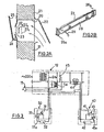
- FIG. 2A shows an air intake opening 20 made, for example, in the window frame 21 of a window and provided with an air intake mouth essentially comprising an external deflector 22, a calibrated orifice and profile 23 formed in an inner plate 24 and an inner deflector 25.
- bimetallic strip is thin enough to be elastically deformable towards the orifice 23 under the effect of a pressure difference existing between the outside and the inside of the window, due for example to the presence of wind.
- This bimetallic strip plays, in a known manner, the role of movable shutter flap giving the mouth a self-adjusting character, that is to say of stabilizing the air inlet flow whatever the pressure difference between the interior and the outside.
- the bimetallic strip 27 is equipped with a film 28 electrically resistant on one of its faces, connected (wires 29) to a supply circuit comprising, as in FIG. 1, a triac and a humidity detector.
- the position 27a of the bimetallic strip shown in solid lines in FIG. 2A symbolizes the rest position corresponding to ambient conditions in which there is no wind, a relatively low internal humidity rate leading to an admission flow d 'average air.
- the position 27b of the bimetallic strip shown in phantom is the result of the existence of wind on the facade of the building or of cold air. This intake flow is then reduced to a minimum, the ambient humidity level remaining low.
- the position 27c of the bimetallic strip is that which it takes in the presence of an excessively high internal humidity rate which has generated a heating spreading the bimetallic strip from the orifice 23 and allowing the admission of an air flow more important. It will be recalled that FIG.
- FIG. 2A is a diagrammatic cross-section of the inlet mouth according to the invention and that the positions indicated are those taken by the central part of the bimetal strip which is held in a sliding manner by its two ends in the slides 26a and 26b. It will be noted that, also with regard to the air intake vents, it may be advantageous to provide a forced opening control to favor the renewal of air through a living room which would be polluted by the smoke. of cigarettes.
- the device according to the invention it is possible by the device according to the invention to control the extraction and the admission of air to the temperature, to the humidity rate and also to take into account the external atmospheric conditions. the room to be ventilated.
- a control of the air flow entering an apartment implies a correlative control of the extracted air flow, and vice versa, so that ventilation is optimized.
- the inlet mouth is denoted 30 and includes the humidity detector 31, the additional resistance 32 of the bimetallic strip (heating film) in series across the secondary of the transformer 12 with one. triac 33 on the trigger 33a which acts the humidity detector 31.
- the extraction mouth is denoted 40 and includes the humidity detector 41, the additional resistance 42 of the bimetallic strip (heating film) in series across the transformer secondary 12 with a triac 43 on the trigger 43a which acts the humidity detector 41.
- Also in series on the triac detector circuit of each mouth is the primary of a step-up transformer 34, 44 whose voltage delivered by the secondary is applied for the transformer 34, to the trigger 43a and for the transformer 44, to the trigger 33a.
- the connection between the secondary of the transformer 34 and the trigger 43a can be interrupted by a manual switch (inverter) which can connect the trigger in its other position to an adequate voltage source. (from a divider 45).
- a manual switch inverter
- the control of each mouth 30, 40 is controlled by the operation of the other.
- the control of the extraction mouth 40 is forced and the control of the intake mouth 30 is controlled by the operation of the extraction mouth 40.
- a switch which would force the opening of the air intake mouth 30, but it is not departing from the scope of the present invention to provide it for, for example, favor the ventilation of a living room where you smoke. In this case, the opening of the extraction mouth 40 will be slaved to that of the mouth kept forced open.
- the heating of the bimetallic strip of a mouth 30 or 40 controlled by the plate 31 or 41 sensitive to the corresponding humidity is the result of the circulation of a charging current through the triac 33 or 43 turned on, this current generating by the transformer 34 or 44 a trigger control voltage 43a or 33a of the other triac 43, 33 making it passing in a ratio corresponding to the intensity of the load current.
- the bimetallic strip of the other mouth is therefore heated to an extent related to the bimetallic strip of the first mouth and the openings of the mouths are then in a relationship allowing good ventilation.
- FIG. 3 relates to the assertion of an extraction mouth to a single intake mouth.
- Each of the intake ports of a dwelling can be connected to the mouth of the kitchen of the same way on condition that a transformer 44 is used having as many secondaries as there are air inlets.
- transformers 34, 44 are only one possible example of sensors for the passage of current in the charging circuit of triacs capable of controlling the trigger.
- Other components can be used such as for example thermistors from other triacs or others making it possible to deliver a current or a voltage controlled as a function of a detected current.
- This inlet mouth 18 is preferably constructed on the same principle as that described in the main patent and shown in FIGS. 2A and 2B and reference will be made to these figures to understand the structure of this mouth.
- this inlet mouth 18 is of the thermoregulating type and also comprises the bimetallic strip 27 shown in attached FIG. 2A constituting the adjustable shutter, which is equipped with a film 28 electrically resistant on one of its faces, and which is connected by wires 29 to the supply circuit 13, being controlled in parallel with that of the mouth 5.
- the installation. ventilation is provided so that the noble rooms or main rooms are equipped with humidity-sensitive intake vents which can be of any humidity-sensitive model and in particular that previously described.
- These intake openings for soft rooms are autonomous and are no longer required to be controlled by the opening of an extraction opening, contrary to what is described in FIGS. 1 to 3.
- the opening of the inlet mouth 18 of the technical part is delayed relative to that of the extraction mouth 5 so as to maintain a vacuum in said part.
- the humidity plate 14 sends a signal to the circuit 13 which then heats the bimetallic strips of the extraction mouth 5 and of the intake mouth 18 in parallel.
- the supply of the bimetallic strip to the inlet mouth 18 can be delayed so as to maintain a vacuum in the housing.
- the invention also makes it possible, as previously described, to simplify the structure of the ventilation installation, by eliminating the need for servo-control between the intake mouth and the extraction mouth. This also eliminates the risk of breakdown due to a failure of the servo system.
- the invention offers the additional technical advantage of making it possible to connect a gas generator which requires a large flow of air.
- the invention finds an interesting explanation in the ventilation and air conditioning industry.
Landscapes
- Engineering & Computer Science (AREA)
- Physics & Mathematics (AREA)
- Chemical & Material Sciences (AREA)
- Combustion & Propulsion (AREA)
- Mechanical Engineering (AREA)
- General Engineering & Computer Science (AREA)
- Fluid Mechanics (AREA)
- General Physics & Mathematics (AREA)
- Automation & Control Theory (AREA)
- Ventilation (AREA)
Applications Claiming Priority (4)
| Application Number | Priority Date | Filing Date | Title |
|---|---|---|---|
| FR8409113A FR2565673B1 (fr) | 1984-06-12 | 1984-06-12 | Bouche et installation de ventilation reglable en fonction de la temperature et du taux d'humidite du flux d'air. |
| FR8409113 | 1984-06-12 | ||
| FR8501315 | 1985-01-30 | ||
| FR8501315A FR2576674B2 (fr) | 1985-01-30 | 1985-01-30 | Installation de ventilation a bouche d'admission situee dans une piece technique sans detecteur d'humidite et a bilame commande en parallele avec celui de la bouche d'extration de type hygroregable |
Publications (2)
| Publication Number | Publication Date |
|---|---|
| EP0165175A2 true EP0165175A2 (de) | 1985-12-18 |
| EP0165175A3 EP0165175A3 (de) | 1986-10-22 |
Family
ID=26224005
Family Applications (1)
| Application Number | Title | Priority Date | Filing Date |
|---|---|---|---|
| EP85401129A Withdrawn EP0165175A3 (de) | 1984-06-12 | 1985-06-07 | Abzug und Lüftungsanlage, regelbar in Abhängigkeit von der Temperatur und dem Feuchtigkeitsgrad des Luftstroms |
Country Status (1)
| Country | Link |
|---|---|
| EP (1) | EP0165175A3 (de) |
Cited By (4)
| Publication number | Priority date | Publication date | Assignee | Title |
|---|---|---|---|---|
| DE3936094A1 (de) * | 1989-10-30 | 1991-05-02 | Hoval Interliz Ag | Verfahren zum regeln von verstellbaren luftverteilern als luftauslass von lueftungs- und klimaanlagen |
| FR2729461A1 (fr) * | 1995-01-17 | 1996-07-19 | Cerga | Dispositif de reglage de la section de passage d'une bouche de ventilation d'air d'un local |
| FR2778230A1 (fr) * | 1998-05-04 | 1999-11-05 | Nicoll Raccords Plastiques | Dispositif de positionnement pour boitier acoustique d'entree d'air dans un batiment |
| FR3095031A1 (fr) * | 2019-04-09 | 2020-10-16 | Anjos Ventilation | Bouche d’extraction d’air |
Family Cites Families (12)
| Publication number | Priority date | Publication date | Assignee | Title |
|---|---|---|---|---|
| US2240390A (en) * | 1938-11-22 | 1941-04-29 | Bendix Aviat Corp | Automatic control device |
| FR1201624A (fr) * | 1958-07-07 | 1960-01-04 | Perfectionnement apporté aux bilames et autres organes métalliques déformables sous l'effet de la chaleur | |
| FR1334650A (fr) * | 1961-09-08 | 1963-08-09 | Texas Instruments Inc | élément thermostatique |
| US3312398A (en) * | 1965-06-28 | 1967-04-04 | Emerson Electric Co | Humidity controller with thermal relay |
| US3442483A (en) * | 1966-12-22 | 1969-05-06 | Dole Valve Co | Fluid flow control valve |
| US3513881A (en) * | 1967-07-24 | 1970-05-26 | Garrett Corp | Flow regulator having thrust recovery |
| DE1808380A1 (de) * | 1968-11-12 | 1970-05-27 | Eickelschulte Hans Ulrich | Vorrichtung zur selbsttaetigen Be- und Entlueftung eines geschlossenen Raumes |
| US3840176A (en) * | 1971-11-04 | 1974-10-08 | Emerson Electric Co | Humidifier control system |
| DE2453757C3 (de) * | 1974-11-13 | 1980-07-24 | Pierburg Gmbh & Co Kg, 4040 Neuss | Thermoventil für Brennkraftmaschinen |
| GB2019609A (en) * | 1978-01-27 | 1979-10-31 | Lovell H | Apparatus for controlling air flow in ventilation systems |
| FR2496238A1 (fr) * | 1980-12-11 | 1982-06-18 | Ventilation Indle Miniere | Bouche pour le montage d'un registre dans une installation de ventilation |
| FR2508606A1 (fr) * | 1981-06-30 | 1982-12-31 | Serva Soc | Procede de regulation de la ventilation d'un local et moyens pour sa mise en oeuvre |
-
1985
- 1985-06-07 EP EP85401129A patent/EP0165175A3/de not_active Withdrawn
Cited By (7)
| Publication number | Priority date | Publication date | Assignee | Title |
|---|---|---|---|---|
| DE3936094A1 (de) * | 1989-10-30 | 1991-05-02 | Hoval Interliz Ag | Verfahren zum regeln von verstellbaren luftverteilern als luftauslass von lueftungs- und klimaanlagen |
| DE3936094C2 (de) * | 1989-10-30 | 1998-11-26 | Hoval Interliz Ag | Verfahren zum Regeln von verstellbaren Luftverteilern als Luftauslaß von Lüftungs- und Klimaanlagen |
| FR2729461A1 (fr) * | 1995-01-17 | 1996-07-19 | Cerga | Dispositif de reglage de la section de passage d'une bouche de ventilation d'air d'un local |
| ES2130900A1 (es) * | 1995-01-17 | 1999-07-01 | Cerga | Dispositivo de regulacion de la seccion de paso de una boca de ventilacion de aire de un local. |
| DE19601453B4 (de) * | 1995-01-17 | 2006-02-02 | Conseils Etudes Et Recherches En Gestion De L'air C.E.R.G.A. | Vorrichtung zur Einstellung des Durchlaßquerschnitts einer Lüftungsöffnung eines Raumes |
| FR2778230A1 (fr) * | 1998-05-04 | 1999-11-05 | Nicoll Raccords Plastiques | Dispositif de positionnement pour boitier acoustique d'entree d'air dans un batiment |
| FR3095031A1 (fr) * | 2019-04-09 | 2020-10-16 | Anjos Ventilation | Bouche d’extraction d’air |
Also Published As
| Publication number | Publication date |
|---|---|
| EP0165175A3 (de) | 1986-10-22 |
Similar Documents
| Publication | Publication Date | Title |
|---|---|---|
| EP0204611B1 (de) | Entlüftungsvorrichtung für Räume und Zugerzeuger für Schornsteine | |
| EP0068917B1 (de) | Verfahren zur Regelung der Belüftung eines Raumes und Mittel zur Ausübung des Verfahrens | |
| WO1999057491A1 (fr) | Procede et dispositif de climatisation | |
| EP0165175A2 (de) | Abzug und Lüftungsanlage, regelbar in Abhängigkeit von der Temperatur und dem Feuchtigkeitsgrad des Luftstroms | |
| EP3130865A1 (de) | Öffnung mit eigener stromversorgung und regulierung des durchsatzes, und regulierverfahren einer entsprechenden kwl-anlage | |
| FR2480908A1 (fr) | Foyer muni d'un limiteur de tirage et d'un systeme de ventilation | |
| FR2640401A1 (fr) | Dispositif de commande electronique de l'alimentation d'une resistance chauffante | |
| FR2783041A1 (fr) | Dispositif de regulation en temperature d'un local notamment d'un chai | |
| FR2565673A1 (fr) | Bouche et installation de ventilation reglable en fonction de la temperature et du taux d'humidite du flux d'air. | |
| FR2911671A1 (fr) | Dispositif d'assistance mecanique pour l'evacuation de flux gazeux plus particulierement destine a un ensemble habitable | |
| EP0011527A1 (de) | Konvektor | |
| FR2556820A1 (fr) | Cheminee de chauffage avec production d'air chaud | |
| EP0312478B1 (de) | Verfahren und Vorrichtung zur Unterdruckbelüftung eines insbesondere zur Geflügelzucht bestimmten Gebäudes | |
| FR2576674A2 (fr) | Installation de ventilation a bouche d'admission situee dans une piece technique sans detecteur d'humidite et a bilame commande en parallele avec celui de la bouche d'extration de type hygroregable | |
| FR2529308A1 (fr) | Groupe de ventilation pour des locaux | |
| EP2998657B1 (de) | Belüftungssystem eines gebäudes und steuerbares mittel zum unterteiltem lufteinlass | |
| EP2442041B1 (de) | Mechanische Belüftungsinstallation durch feuchtigkeitsregulierte Belüftung, und zugehöriges Verfahren | |
| FR2835598A1 (fr) | Installation de ventilation mecanique controlee equipee d'un dispositif de pilotage | |
| EP4191151A1 (de) | Feuchtigkeitseinstellbare vorrichtung zur luftextraktion oder -einblasung für eine belüftungsanlage und belüftungsanlage mit einer solchen vorrichtung | |
| FR2918721A1 (fr) | Appareil de controle de debit de fluide gazeux. | |
| FR2587458A2 (fr) | Dispositif d'aeration des locaux et de tirage des cheminees | |
| FR2588945A1 (fr) | Bouche d'extraction ou d'admission d'air ou de gaz pour la ventilation d'un local a obturateur reglable commande par un bilame | |
| FR2468839A1 (fr) | Ensemble combine de cuisson d'aliments et chauffage de locaux | |
| CH341957A (fr) | Séchoir pour cheveux | |
| EP4191157A1 (de) | System zur steuerung einer feuchtigkeitseinstellbaren luftextraktionsvorrichtung für eine belüftungsanlage und belüftungsanlage mit solch einem steuerungssystem |
Legal Events
| Date | Code | Title | Description |
|---|---|---|---|
| PUAI | Public reference made under article 153(3) epc to a published international application that has entered the european phase |
Free format text: ORIGINAL CODE: 0009012 |
|
| AK | Designated contracting states |
Designated state(s): BE DE GB IT NL SE |
|
| PUAL | Search report despatched |
Free format text: ORIGINAL CODE: 0009013 |
|
| AK | Designated contracting states |
Kind code of ref document: A3 Designated state(s): BE DE GB IT NL SE |
|
| RAP1 | Party data changed (applicant data changed or rights of an application transferred) |
Owner name: FLAEKT AB |
|
| 17P | Request for examination filed |
Effective date: 19861111 |
|
| 17Q | First examination report despatched |
Effective date: 19870407 |
|
| RAP3 | Party data changed (applicant data changed or rights of an application transferred) |
Owner name: FLAEKT AB |
|
| STAA | Information on the status of an ep patent application or granted ep patent |
Free format text: STATUS: THE APPLICATION IS DEEMED TO BE WITHDRAWN |
|
| 18D | Application deemed to be withdrawn |
Effective date: 19890509 |
|
| RIN1 | Information on inventor provided before grant (corrected) |
Inventor name: ROUSSEL, MICHEL |