EP0165189A1 - Vorrichtung zum Halten von plattenförmigen Materialien auf den Tischen einer Sägemaschine - Google Patents
Vorrichtung zum Halten von plattenförmigen Materialien auf den Tischen einer Sägemaschine Download PDFInfo
- Publication number
- EP0165189A1 EP0165189A1 EP85440028A EP85440028A EP0165189A1 EP 0165189 A1 EP0165189 A1 EP 0165189A1 EP 85440028 A EP85440028 A EP 85440028A EP 85440028 A EP85440028 A EP 85440028A EP 0165189 A1 EP0165189 A1 EP 0165189A1
- Authority
- EP
- European Patent Office
- Prior art keywords
- vertical
- bearings
- integral
- pressure bar
- sole
- Prior art date
- Legal status (The legal status is an assumption and is not a legal conclusion. Google has not performed a legal analysis and makes no representation as to the accuracy of the status listed.)
- Granted
Links
- 230000007246 mechanism Effects 0.000 claims abstract description 52
- 238000006073 displacement reaction Methods 0.000 claims abstract description 6
- 125000006850 spacer group Chemical group 0.000 claims description 3
- 241000763859 Dyckia brevifolia Species 0.000 abstract 1
- 230000005540 biological transmission Effects 0.000 abstract 1
- 125000004122 cyclic group Chemical group 0.000 description 1
- 238000004519 manufacturing process Methods 0.000 description 1
- 230000001681 protective effect Effects 0.000 description 1
- 230000000284 resting effect Effects 0.000 description 1
Images


Classifications
-
- B—PERFORMING OPERATIONS; TRANSPORTING
- B23—MACHINE TOOLS; METAL-WORKING NOT OTHERWISE PROVIDED FOR
- B23D—PLANING; SLOTTING; SHEARING; BROACHING; SAWING; FILING; SCRAPING; LIKE OPERATIONS FOR WORKING METAL BY REMOVING MATERIAL, NOT OTHERWISE PROVIDED FOR
- B23D47/00—Sawing machines or sawing devices working with circular saw blades, characterised only by constructional features of particular parts
- B23D47/04—Sawing machines or sawing devices working with circular saw blades, characterised only by constructional features of particular parts of devices for feeding, positioning, clamping, or rotating work
Definitions
- the invention relates to a device for holding sheet materials on the tables of a sawing machine, in particular for cutting the last strip.
- Plate sawing machines include, among other things, a movable guide exerting a cyclic thrust on the stack of plate materials as and when cutting.
- This movable guide comprises collets consisting of a lower spout on which the stack rests and an upper spout exerting pressure on said stack.
- This movable guide is placed at the rear end of the stack seen in the direction of advance thereof and it proves necessary to hold the stack of material in plates during cutting.
- a support mechanism has been designed located above the saw blade and which comes, at each cutting cycle, to be placed on top of the pile.
- the cutting cycle is planned so as to use the last band provided that it is wider than a given width depending on the characteristics of each type of sawing machine.
- One of these known devices comprises a jack secured to the support mechanism and placed beyond the cutting line.
- the actuator is actuated first and, when the latter is in contact with the stack of plate materials, the supporting mechanism is actuated in a second step.
- this device has several drawbacks.
- the cylinders are fixed on the support mechanism and exert pressure on the pile during the descent phase of the support mechanism. Frequently, the latter consists of a very long beam. This guidance is not provided in the center of the stack. This results in a lateral displacement of the cylinders under the combined action of the clamping forces of these cylinders and the downward movement of the support mechanism. This lateral movement causes the stack of different plates to slide, which considerably reduces the precision of the cut.
- a device has been designed in which the jack or jacks are separated from the support mechanism.
- the cylinders are integral with a support beam parallel to the support beam of the support mechanism. The operation is as follows: during the advance of the stack of plate materials, the support mechanism and the jacks are in the high position. Then, the cylinders are lowered coming to rest on the top of the piles, then the support mechanism is lowered.
- the support disc is in contact with the strip only over a small part of its surface.
- the force provided by the jack is not uniformly distributed and the support disc is cantilevered. This results in a deflection of the pistons of the cylinders causing a sliding of the different plate materials stacked on each other. This results in poor sawing precision incompatible with the future destination of the cut plates.
- the present invention aims to remedy these drawbacks.
- the invention as characterized in the claims, solves the problem of creating a device for holding sheet materials on the tables of a sawing machine, in particular for cutting the last strip comprising a mechanism for relay provided with a transverse pressure bar extending over the entire width of the tables and subjected to a vertical movement caused by motor means cooperating with the ends of said pressure bar, the latter being parallel and placed in the immediate vicinity of a beam of a support mechanism.
- the device makes it possible to improve the cutting precision, in particular when sawing the last strip.
- the pressure bar remains valid for all the widths of bands obtained by sawing the stack of sheet materials and that it makes it possible to clamp this stack as close as possible to the beam of the support device.
- the clamping force is regularly distributed over the length of the stack.
- the holding device 1 enclosed in a protective cover 2, consists of a support mechanism 3 and a relay mechanism 4.
- the support mechanism 3 comprises two beams 5 and 6 between which is located a free space 7 for the passage of the saw blade.
- a pressure bar 8 of the relay mechanism 4 In the immediate vicinity of the beam 6 placed downstream of the saw blade is disposed a pressure bar 8 of the relay mechanism 4.
- the operation of the holding device 1 is as follows: during the advance of the stack of materials in plates, the support mechanism 3 and the relay mechanism 4 are in the high position as shown in dotted lines in FIG. 1. After positioning the stack of plate materials, the two mechanisms 3 and 4 are lowered. lower 9, 10 of the two beams 5 and 6 make contact with said stack. It is the same for the lower edge 11 of the pressure bar 8 of the relay mechanism 4.
- the strip of the stack located beyond the saw cut 12 is held simultaneously by the lower edge 10 of the beam 6 of the support mechanism 3 and by the lower edge 11 of the pressure bar 8 of the relay mechanism 4. Due to the double action, the strip located beyond the saw cut 12 is strongly maintained and there can be no sliding of a plate relative to its neighbor. Furthermore, the front face 13 of the pressure bar 8 can be located in the immediate vicinity of the rear face 14 of the beam 6. As a result, the strip can be of narrow width of the order of thirty to forty millimeters.
- the relay mechanism 4 comprises, as described above, a pressure bar 8 whose lower edge 11 is provided with an elastic lip 15 , including a rubber lip to avoid damaging the top of the stack of plate materials.
- This elastic lip 15 is held by a clamp 16 integral with said lower edge 11.
- Each end 17 of the pressure bar 8 cooperates with a set of motor means involving the pressure bar 8 in a vertical movement either upwards or low.
- only one set of drive means will be described, it being understood that the two sets are identical and are arranged at the two ends of the pressure bar 8 whose length corresponds to the length of the table before 18 of the sawing machine provided with the holding device 1 according to the invention.
- the set of drive means comprises a vertical support 19, the front face 20 of which is made integral with the rear face 21 of the pressure bar 8 by fastening elements 22, 23, 24, 25. However, it is necessary that this vertical support .19 is strictly parallel to the pressure bar 8. For this purpose, provision is made. Adjust screws 26, 27, 28 ... screwed into tapped holes 29, 30, 31 ... made in the vertical support 19 and bearing against the rear face 21 of the pressure bar 8.
- On the rear face 33 of the vertical support 19 are fixed two bearings 34, 35 comprising a bore 36, 37 in which is housed a bearing 38, 39 provided with a shoulder 40, 41 bearing against one of the faces 42, 43 of the bearings 34, 35.
- a guide pin 44 whose lower end 45 has a shoulder 46 resting on the upper face 47 of a sleeve 48 secured to a sole 49.
- the latter comprises on its lower face 50 a housing 51 in which is embedded a fixing plate 52 crossed by a screw fixing 53, the threaded end 54 of which is screwed into a tapped hole 55 made in the lower end 45, the latter passing through a bore 56 produced in the socket 48 and a hole 57 made in the seed 49 and leading to the housing 51
- the sole 49 is made integral with the front table 18 by fastening elements 58, 59, 60 and the horizontality can be adjusted by adjustment screws 61, 62, 63, 61a, 63a.
- the guide pin 44 includes a rack 64.
- the teeth 65, 66 of the rack 64 cooperate with the teeth 67, 68 ... of a toothed pinion 69.
- the latter made integral in rotation by a pin 70, is disposed at the end 71 of a transverse shaft 72 connecting together the drive means located on each side of the pressure bar 8.
- the transverse shaft 72 rotates in a bearing 73 engaged in a bore 74 made in a vertical console 75 made integral with the bearings 34, 35 by fastening elements 76, 77.
- At least one set of motor means comprises a jack 78 whose lower end 79 is made integral with the sole 49 by fastening elements 80, 81. This lower end 79 is connected to an upper end 82 by rods 83, 84 , 85, 86.
- the end 87 of the piston 88 of this jack 78 is secured to a cross member 89 itself secured to the vertical support 19.
- the piston 88 exerts either a push or a pull on the cross member 89 which transmits this to the vertical support 19 and, consequently, to the pressure bar 8.
- the rack 64 causes the rotation of the transverse shaft 72 by means of the toothed pinion 69.
- the rotation of the transverse shaft 72 drives a toothed pinion of the second set of motor means.
- the two ends 17 of the pressure bar 8 are given identical vertical displacement.
- it ensures the horizontality of the pressure bar 8 and a uniform pressure over the entire width of the stack of plate materials.
- the vertical axis 90 of the guide axis 44 is located as close as possible to the edge 91 of the sole 49 to bring the pressure bar 8 as close as possible to the beam 6 of the mechanism support 3.
- the transverse shaft 72 is held by bearings 92 made integral by fastening elements 93 of a tubular section 94 integral with the rear face 21 of the pressure bar 8.
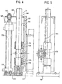
- FIGS. 4, 5 and 8 showing the support mechanism 3.
- the structure of this mechanism is practically the same as that of the relay mechanism 4.
- the two beams 5 and 6 are connected together by a spacer 96.
- Each end 117 of this assembly formed by the two beams 5, 6 and the spacer 96 is secured to an intermediate support 97, one of the ends 98 of which is secured to one of the faces 99 of a vertical support 119.
- This intermediate support 97 is arranged perpendicular to said vertical support 119 and parallel to the beams 5 and 6.
- the other face 133 of the vertical support 119 is provided with two bearings 134, 135 provided with a pad 138, 139 traversed vertically by a guide axis 144.
- the latter is integral with a sole 149 fixed to the front table 18.
- the vertical axis 190 of the guide axis 144 is located in the vertical plane 100 of the sole 149.
- Said guide axis 144 comprises a rack 164 on which a toothed pinion moves 169.
- This is integral in rotation with a transverse shaft 172 connecting together the drive means located on each side of the set of beams 5, 6.
- This transverse shaft 172 is held by bearings 192 provided with bearings integral with the rear face 14 of the beam 6.
- the upper end of the vertical support 119 comprises a cross member 189 on which is fixed the end 187 of a piston 188 of a jack 178.
- the lower end 179 of this jack 178 is integral with the sole 149.
- the piston 188 subjects, by means of the cross member 189, the vertical support 119 to a vertical movement.
- This also causes, on the one hand, the vertical movement of all the beams 5, 6 and, on the other hand, the rotation of the toothed pinion 169 and, consequently, the rotation of the toothed pinion 16.9 causes , by the rotation of the transverse shaft 172, the vertical displacement of the vertical support located on the other side of the set of beams 5, 6.
- the transverse shaft 172 causes, by the rotation of the transverse shaft 172, the vertical displacement of the vertical support located on the other side of the set of beams 5, 6.
Landscapes
- Engineering & Computer Science (AREA)
- Mechanical Engineering (AREA)
- Sawing (AREA)
- Mechanical Treatment Of Semiconductor (AREA)
- Sheets, Magazines, And Separation Thereof (AREA)
- Pile Receivers (AREA)
Priority Applications (1)
| Application Number | Priority Date | Filing Date | Title |
|---|---|---|---|
| AT85440028T ATE41750T1 (de) | 1984-05-09 | 1985-05-02 | Vorrichtung zum halten von plattenfoermigen materialien auf den tischen einer saegemaschine. |
Applications Claiming Priority (2)
| Application Number | Priority Date | Filing Date | Title |
|---|---|---|---|
| FR8407251 | 1984-05-09 | ||
| FR8407251A FR2564014B1 (fr) | 1984-05-09 | 1984-05-09 | Dispositif de maintien des materiaux en plaques sur les tables d'une machine a scier |
Publications (2)
| Publication Number | Publication Date |
|---|---|
| EP0165189A1 true EP0165189A1 (de) | 1985-12-18 |
| EP0165189B1 EP0165189B1 (de) | 1989-03-29 |
Family
ID=9303862
Family Applications (1)
| Application Number | Title | Priority Date | Filing Date |
|---|---|---|---|
| EP85440028A Expired EP0165189B1 (de) | 1984-05-09 | 1985-05-02 | Vorrichtung zum Halten von plattenförmigen Materialien auf den Tischen einer Sägemaschine |
Country Status (5)
| Country | Link |
|---|---|
| EP (1) | EP0165189B1 (de) |
| JP (1) | JPS60238224A (de) |
| AT (1) | ATE41750T1 (de) |
| DE (1) | DE3569086D1 (de) |
| FR (1) | FR2564014B1 (de) |
Cited By (2)
| Publication number | Priority date | Publication date | Assignee | Title |
|---|---|---|---|---|
| EP0249058A1 (de) * | 1986-06-11 | 1987-12-16 | GIBEN IMPIANTI S.p.A. | Druckbalken für Sägemaschinen |
| CN109926649A (zh) * | 2018-02-01 | 2019-06-25 | 宋怡 | 用于切割机的限位机构以及用于电力拉线棒的切割机 |
Families Citing this family (1)
| Publication number | Priority date | Publication date | Assignee | Title |
|---|---|---|---|---|
| CN106476082B (zh) * | 2016-11-15 | 2018-10-30 | 宣城市宣州区峰刚木工板厂 | 一种大型方木板材加工设备 |
Citations (5)
| Publication number | Priority date | Publication date | Assignee | Title |
|---|---|---|---|---|
| DE58887C (de) * | Frau M. MEYER in Dresden-Altstadt, Schlössergasse 2 | Beschneidmaschine für Stoffmuster und Papier | ||
| US1976972A (en) * | 1934-10-16 | Cutting machine | ||
| DE845935C (de) * | 1949-07-05 | 1952-08-07 | Karl Krause Fa | Dreimesser-Schneidmaschine zum Beschneiden von Buch-, Papier- od. dgl. Stapeln |
| FR1435714A (fr) * | 1964-06-08 | 1966-04-15 | Pacific Press & Shear Corp | Dispositif de maintien pour une machine à cisailler ou analogue |
| FR2248916A1 (en) * | 1973-10-30 | 1975-05-23 | Schelling & Co | Circular saw workpiece pressure beam - has inflatable hose between workpiece and beam step |
-
1984
- 1984-05-09 FR FR8407251A patent/FR2564014B1/fr not_active Expired
-
1985
- 1985-05-02 EP EP85440028A patent/EP0165189B1/de not_active Expired
- 1985-05-02 DE DE8585440028T patent/DE3569086D1/de not_active Expired
- 1985-05-02 AT AT85440028T patent/ATE41750T1/de not_active IP Right Cessation
- 1985-05-08 JP JP60096131A patent/JPS60238224A/ja active Pending
Patent Citations (5)
| Publication number | Priority date | Publication date | Assignee | Title |
|---|---|---|---|---|
| DE58887C (de) * | Frau M. MEYER in Dresden-Altstadt, Schlössergasse 2 | Beschneidmaschine für Stoffmuster und Papier | ||
| US1976972A (en) * | 1934-10-16 | Cutting machine | ||
| DE845935C (de) * | 1949-07-05 | 1952-08-07 | Karl Krause Fa | Dreimesser-Schneidmaschine zum Beschneiden von Buch-, Papier- od. dgl. Stapeln |
| FR1435714A (fr) * | 1964-06-08 | 1966-04-15 | Pacific Press & Shear Corp | Dispositif de maintien pour une machine à cisailler ou analogue |
| FR2248916A1 (en) * | 1973-10-30 | 1975-05-23 | Schelling & Co | Circular saw workpiece pressure beam - has inflatable hose between workpiece and beam step |
Cited By (3)
| Publication number | Priority date | Publication date | Assignee | Title |
|---|---|---|---|---|
| EP0249058A1 (de) * | 1986-06-11 | 1987-12-16 | GIBEN IMPIANTI S.p.A. | Druckbalken für Sägemaschinen |
| CN109926649A (zh) * | 2018-02-01 | 2019-06-25 | 宋怡 | 用于切割机的限位机构以及用于电力拉线棒的切割机 |
| CN109926649B (zh) * | 2018-02-01 | 2020-06-05 | 南京溧水高新创业投资管理有限公司 | 用于切割机的限位机构以及用于电力拉线棒的切割机 |
Also Published As
| Publication number | Publication date |
|---|---|
| JPS60238224A (ja) | 1985-11-27 |
| FR2564014A1 (fr) | 1985-11-15 |
| FR2564014B1 (fr) | 1986-09-26 |
| DE3569086D1 (en) | 1989-05-03 |
| ATE41750T1 (de) | 1989-04-15 |
| EP0165189B1 (de) | 1989-03-29 |
Similar Documents
| Publication | Publication Date | Title |
|---|---|---|
| FR2584003A1 (fr) | Appareil de coupe de produits longs | |
| EP1771662A1 (de) | Peristaltische pumpenkassette mit einer einheit zum einstellen einer rohrklemmung | |
| EP0153262B1 (de) | Führungsvorrichtung für einen Träger in einer Sägemaschine | |
| EP0165189B1 (de) | Vorrichtung zum Halten von plattenförmigen Materialien auf den Tischen einer Sägemaschine | |
| EP0258122B1 (de) | Fräsvorrichtung zum Ausheben von Graben im Boden | |
| FR2545463A1 (fr) | Appareil de collage de bandes | |
| FR2815622A1 (fr) | Dispositif de raccordement bout a bout pour une machine a derouler en continu | |
| EP0317391A1 (de) | Vorrichtung zur Aufrechterhaltung der Position von annähernd parallelepipedförmigen Teilen | |
| FR3093455A1 (fr) | Dispositif de sciage | |
| CH469522A (fr) | Cisaille-guillotine hydraulique | |
| FR2611573A1 (fr) | Dispositif pour fendre les buches dans le sens de leur longueur | |
| BE1029942B1 (fr) | Diviseuse de pâte compacte | |
| EP0161197A1 (de) | Vorrichtung zum Verschliessen der Spalte eines Sägemaschinentisches | |
| CA2077730A1 (fr) | Attendrisseur | |
| EP0219444B1 (de) | Holzspaltgerät mit drehendem Spaltkegel | |
| FR2559992A1 (fr) | Appareil de support de barre de coupe et dispositif a barre de coupe pour faucheuse rotative | |
| FR2527981A1 (fr) | Dispositif de pliage automatique pour plaque offset | |
| CA1326246C (fr) | Dispositif de serrage de cadres | |
| FR2520793A1 (fr) | Machine automatique destinee a la mise en place des joints d'etancheite dans les rainures notamment de profiles-bois | |
| BE542132A (fr) | Perfectionnements aux scies mecaniques | |
| BE1023578B1 (fr) | Diviseuse de pâte avec une grille déformable | |
| FR2579508A1 (fr) | Poussoir pour scie a ruban | |
| FR2530612A1 (fr) | Machine de decoupage d'un carreau de vitre plan, pouvant etre inseree dans une chaine de coupe de carreaux | |
| FR2559708A1 (fr) | Dispositif de serrage vertical et horizontal pour machine a scier | |
| FR2601891A1 (fr) | Machine a graver |
Legal Events
| Date | Code | Title | Description |
|---|---|---|---|
| PUAI | Public reference made under article 153(3) epc to a published international application that has entered the european phase |
Free format text: ORIGINAL CODE: 0009012 |
|
| AK | Designated contracting states |
Designated state(s): AT BE CH DE GB IT LI LU NL SE |
|
| 17P | Request for examination filed |
Effective date: 19860531 |
|
| 17Q | First examination report despatched |
Effective date: 19870529 |
|
| GRAA | (expected) grant |
Free format text: ORIGINAL CODE: 0009210 |
|
| AK | Designated contracting states |
Kind code of ref document: B1 Designated state(s): AT BE CH DE GB IT LI LU NL SE |
|
| PG25 | Lapsed in a contracting state [announced via postgrant information from national office to epo] |
Ref country code: IT Free format text: LAPSE BECAUSE OF FAILURE TO SUBMIT A TRANSLATION OF THE DESCRIPTION OR TO PAY THE FEE WITHIN THE PRESCRIBED TIME-LIMIT;WARNING: LAPSES OF ITALIAN PATENTS WITH EFFECTIVE DATE BEFORE 2007 MAY HAVE OCCURRED AT ANY TIME BEFORE 2007. THE CORRECT EFFECTIVE DATE MAY BE DIFFERENT FROM THE ONE RECORDED. Effective date: 19890329 Ref country code: SE Effective date: 19890329 Ref country code: AT Effective date: 19890329 Ref country code: NL Effective date: 19890329 |
|
| REF | Corresponds to: |
Ref document number: 41750 Country of ref document: AT Date of ref document: 19890415 Kind code of ref document: T |
|
| REF | Corresponds to: |
Ref document number: 3569086 Country of ref document: DE Date of ref document: 19890503 |
|
| GBT | Gb: translation of ep patent filed (gb section 77(6)(a)/1977) | ||
| NLV1 | Nl: lapsed or annulled due to failure to fulfill the requirements of art. 29p and 29m of the patents act | ||
| PLBE | No opposition filed within time limit |
Free format text: ORIGINAL CODE: 0009261 |
|
| STAA | Information on the status of an ep patent application or granted ep patent |
Free format text: STATUS: NO OPPOSITION FILED WITHIN TIME LIMIT |
|
| 26N | No opposition filed | ||
| PGFP | Annual fee paid to national office [announced via postgrant information from national office to epo] |
Ref country code: GB Payment date: 19920505 Year of fee payment: 8 |
|
| PGFP | Annual fee paid to national office [announced via postgrant information from national office to epo] |
Ref country code: CH Payment date: 19920518 Year of fee payment: 8 |
|
| PGFP | Annual fee paid to national office [announced via postgrant information from national office to epo] |
Ref country code: BE Payment date: 19920604 Year of fee payment: 8 |
|
| PGFP | Annual fee paid to national office [announced via postgrant information from national office to epo] |
Ref country code: LU Payment date: 19920811 Year of fee payment: 8 |
|
| EPTA | Lu: last paid annual fee | ||
| PG25 | Lapsed in a contracting state [announced via postgrant information from national office to epo] |
Ref country code: GB Effective date: 19930502 Ref country code: LU Free format text: LAPSE BECAUSE OF NON-PAYMENT OF DUE FEES Effective date: 19930502 |
|
| PG25 | Lapsed in a contracting state [announced via postgrant information from national office to epo] |
Ref country code: BE Effective date: 19930531 Ref country code: LI Effective date: 19930531 Ref country code: CH Effective date: 19930531 |
|
| BERE | Be: lapsed |
Owner name: S.A. SMID Effective date: 19930531 |
|
| GBPC | Gb: european patent ceased through non-payment of renewal fee |
Effective date: 19930502 |
|
| REG | Reference to a national code |
Ref country code: CH Ref legal event code: PL |
|
| PGFP | Annual fee paid to national office [announced via postgrant information from national office to epo] |
Ref country code: DE Payment date: 19980511 Year of fee payment: 14 |
|
| PG25 | Lapsed in a contracting state [announced via postgrant information from national office to epo] |
Ref country code: DE Free format text: LAPSE BECAUSE OF NON-PAYMENT OF DUE FEES Effective date: 20000301 |