EP0165224B1 - Equipement de chauffe directe - Google Patents
Equipement de chauffe directe Download PDFInfo
- Publication number
- EP0165224B1 EP0165224B1 EP85870059A EP85870059A EP0165224B1 EP 0165224 B1 EP0165224 B1 EP 0165224B1 EP 85870059 A EP85870059 A EP 85870059A EP 85870059 A EP85870059 A EP 85870059A EP 0165224 B1 EP0165224 B1 EP 0165224B1
- Authority
- EP
- European Patent Office
- Prior art keywords
- drum
- disc
- pins
- fuel
- pulverising
- Prior art date
- Legal status (The legal status is an assumption and is not a legal conclusion. Google has not performed a legal analysis and makes no representation as to the accuracy of the status listed.)
- Expired
Links
- 238000010304 firing Methods 0.000 title abstract 2
- 239000000446 fuel Substances 0.000 claims abstract description 48
- 238000002485 combustion reaction Methods 0.000 claims abstract description 26
- XLYOFNOQVPJJNP-UHFFFAOYSA-N water Substances O XLYOFNOQVPJJNP-UHFFFAOYSA-N 0.000 claims abstract description 17
- 239000004449 solid propellant Substances 0.000 claims abstract description 13
- 239000012530 fluid Substances 0.000 claims abstract description 6
- 238000011144 upstream manufacturing Methods 0.000 claims abstract description 5
- 238000010438 heat treatment Methods 0.000 claims description 23
- 238000009434 installation Methods 0.000 claims description 19
- 239000000463 material Substances 0.000 claims description 11
- 238000009527 percussion Methods 0.000 claims description 6
- 239000000725 suspension Substances 0.000 claims description 6
- 238000005299 abrasion Methods 0.000 claims description 4
- 238000007599 discharging Methods 0.000 claims description 3
- 230000005484 gravity Effects 0.000 claims description 2
- 238000003466 welding Methods 0.000 claims description 2
- 239000003795 chemical substances by application Substances 0.000 claims 7
- 235000013599 spices Nutrition 0.000 claims 1
- 238000000034 method Methods 0.000 abstract description 3
- 238000000227 grinding Methods 0.000 description 48
- 239000007800 oxidant agent Substances 0.000 description 17
- 230000001590 oxidative effect Effects 0.000 description 11
- 239000003517 fume Substances 0.000 description 5
- VTYYLEPIZMXCLO-UHFFFAOYSA-L Calcium carbonate Chemical compound [Ca+2].[O-]C([O-])=O VTYYLEPIZMXCLO-UHFFFAOYSA-L 0.000 description 4
- ODINCKMPIJJUCX-UHFFFAOYSA-N Calcium oxide Chemical compound [Ca]=O ODINCKMPIJJUCX-UHFFFAOYSA-N 0.000 description 4
- CDBYLPFSWZWCQE-UHFFFAOYSA-L Sodium Carbonate Chemical compound [Na+].[Na+].[O-]C([O-])=O CDBYLPFSWZWCQE-UHFFFAOYSA-L 0.000 description 4
- 239000012298 atmosphere Substances 0.000 description 4
- 230000000694 effects Effects 0.000 description 4
- 239000007789 gas Substances 0.000 description 4
- 238000004519 manufacturing process Methods 0.000 description 4
- 239000002245 particle Substances 0.000 description 4
- BWHMMNNQKKPAPP-UHFFFAOYSA-L potassium carbonate Chemical compound [K+].[K+].[O-]C([O-])=O BWHMMNNQKKPAPP-UHFFFAOYSA-L 0.000 description 4
- 239000000126 substance Substances 0.000 description 4
- 241001417494 Sciaenidae Species 0.000 description 3
- 229910000831 Steel Inorganic materials 0.000 description 3
- -1 for example Chemical compound 0.000 description 3
- 239000000203 mixture Substances 0.000 description 3
- 238000004064 recycling Methods 0.000 description 3
- 239000010959 steel Substances 0.000 description 3
- OKTJSMMVPCPJKN-UHFFFAOYSA-N Carbon Chemical compound [C] OKTJSMMVPCPJKN-UHFFFAOYSA-N 0.000 description 2
- 229910001018 Cast iron Inorganic materials 0.000 description 2
- NINIDFKCEFEMDL-UHFFFAOYSA-N Sulfur Chemical compound [S] NINIDFKCEFEMDL-UHFFFAOYSA-N 0.000 description 2
- 229910000019 calcium carbonate Inorganic materials 0.000 description 2
- 239000000292 calcium oxide Substances 0.000 description 2
- 235000012255 calcium oxide Nutrition 0.000 description 2
- 239000003245 coal Substances 0.000 description 2
- 238000000576 coating method Methods 0.000 description 2
- 238000004880 explosion Methods 0.000 description 2
- 239000010881 fly ash Substances 0.000 description 2
- 230000003472 neutralizing effect Effects 0.000 description 2
- 229910000027 potassium carbonate Inorganic materials 0.000 description 2
- 238000011084 recovery Methods 0.000 description 2
- 229910000029 sodium carbonate Inorganic materials 0.000 description 2
- 239000007787 solid Substances 0.000 description 2
- 239000011593 sulfur Substances 0.000 description 2
- 229910052717 sulfur Inorganic materials 0.000 description 2
- VYZAMTAEIAYCRO-UHFFFAOYSA-N Chromium Chemical compound [Cr] VYZAMTAEIAYCRO-UHFFFAOYSA-N 0.000 description 1
- 229910018487 Ni—Cr Inorganic materials 0.000 description 1
- 239000004698 Polyethylene Substances 0.000 description 1
- VYPSYNLAJGMNEJ-UHFFFAOYSA-N Silicium dioxide Chemical compound O=[Si]=O VYPSYNLAJGMNEJ-UHFFFAOYSA-N 0.000 description 1
- 238000005054 agglomeration Methods 0.000 description 1
- 230000002776 aggregation Effects 0.000 description 1
- 239000002956 ash Substances 0.000 description 1
- 230000005540 biological transmission Effects 0.000 description 1
- 238000005219 brazing Methods 0.000 description 1
- 229910052799 carbon Inorganic materials 0.000 description 1
- 238000005266 casting Methods 0.000 description 1
- 238000005119 centrifugation Methods 0.000 description 1
- 229910010293 ceramic material Inorganic materials 0.000 description 1
- 238000006243 chemical reaction Methods 0.000 description 1
- 229910052804 chromium Inorganic materials 0.000 description 1
- 239000011651 chromium Substances 0.000 description 1
- VNNRSPGTAMTISX-UHFFFAOYSA-N chromium nickel Chemical compound [Cr].[Ni] VNNRSPGTAMTISX-UHFFFAOYSA-N 0.000 description 1
- 239000011248 coating agent Substances 0.000 description 1
- 238000004939 coking Methods 0.000 description 1
- 239000000567 combustion gas Substances 0.000 description 1
- 230000006835 compression Effects 0.000 description 1
- 238000007906 compression Methods 0.000 description 1
- 238000010276 construction Methods 0.000 description 1
- 238000010411 cooking Methods 0.000 description 1
- 238000005265 energy consumption Methods 0.000 description 1
- 238000005242 forging Methods 0.000 description 1
- 239000005350 fused silica glass Substances 0.000 description 1
- 239000011521 glass Substances 0.000 description 1
- 230000001788 irregular Effects 0.000 description 1
- 239000007788 liquid Substances 0.000 description 1
- 238000003754 machining Methods 0.000 description 1
- 238000012423 maintenance Methods 0.000 description 1
- 239000012299 nitrogen atmosphere Substances 0.000 description 1
- 229920001748 polybutylene Polymers 0.000 description 1
- 229920000573 polyethylene Polymers 0.000 description 1
- 229920000098 polyolefin Polymers 0.000 description 1
- 229920002635 polyurethane Polymers 0.000 description 1
- 239000004814 polyurethane Substances 0.000 description 1
- 229910052573 porcelain Inorganic materials 0.000 description 1
- 238000000746 purification Methods 0.000 description 1
- 230000035939 shock Effects 0.000 description 1
- 238000005245 sintering Methods 0.000 description 1
- 239000007921 spray Substances 0.000 description 1
- 238000003860 storage Methods 0.000 description 1
- LSNNMFCWUKXFEE-UHFFFAOYSA-L sulfite Chemical class [O-]S([O-])=O LSNNMFCWUKXFEE-UHFFFAOYSA-L 0.000 description 1
- 150000003467 sulfuric acid derivatives Chemical class 0.000 description 1
Images
Classifications
-
- F—MECHANICAL ENGINEERING; LIGHTING; HEATING; WEAPONS; BLASTING
- F16—ENGINEERING ELEMENTS AND UNITS; GENERAL MEASURES FOR PRODUCING AND MAINTAINING EFFECTIVE FUNCTIONING OF MACHINES OR INSTALLATIONS; THERMAL INSULATION IN GENERAL
- F16C—SHAFTS; FLEXIBLE SHAFTS; ELEMENTS OR CRANKSHAFT MECHANISMS; ROTARY BODIES OTHER THAN GEARING ELEMENTS; BEARINGS
- F16C13/00—Rolls, drums, discs, or the like; Bearings or mountings therefor
- F16C13/02—Bearings
- F16C13/04—Bearings with only partial enclosure of the member to be borne; Bearings with local support at two or more points
-
- B—PERFORMING OPERATIONS; TRANSPORTING
- B02—CRUSHING, PULVERISING, OR DISINTEGRATING; PREPARATORY TREATMENT OF GRAIN FOR MILLING
- B02C—CRUSHING, PULVERISING, OR DISINTEGRATING IN GENERAL; MILLING GRAIN
- B02C13/00—Disintegrating by mills having rotary beater elements ; Hammer mills
- B02C13/22—Disintegrating by mills having rotary beater elements ; Hammer mills with intermeshing pins ; Pin Disk Mills
-
- B—PERFORMING OPERATIONS; TRANSPORTING
- B02—CRUSHING, PULVERISING, OR DISINTEGRATING; PREPARATORY TREATMENT OF GRAIN FOR MILLING
- B02C—CRUSHING, PULVERISING, OR DISINTEGRATING IN GENERAL; MILLING GRAIN
- B02C17/00—Disintegrating by tumbling mills, i.e. mills having a container charged with the material to be disintegrated with or without special disintegrating members such as pebbles or balls
- B02C17/04—Disintegrating by tumbling mills, i.e. mills having a container charged with the material to be disintegrated with or without special disintegrating members such as pebbles or balls with unperforated container
-
- B—PERFORMING OPERATIONS; TRANSPORTING
- B02—CRUSHING, PULVERISING, OR DISINTEGRATING; PREPARATORY TREATMENT OF GRAIN FOR MILLING
- B02C—CRUSHING, PULVERISING, OR DISINTEGRATING IN GENERAL; MILLING GRAIN
- B02C17/00—Disintegrating by tumbling mills, i.e. mills having a container charged with the material to be disintegrated with or without special disintegrating members such as pebbles or balls
- B02C17/18—Details
-
- B—PERFORMING OPERATIONS; TRANSPORTING
- B02—CRUSHING, PULVERISING, OR DISINTEGRATING; PREPARATORY TREATMENT OF GRAIN FOR MILLING
- B02C—CRUSHING, PULVERISING, OR DISINTEGRATING IN GENERAL; MILLING GRAIN
- B02C19/00—Other disintegrating devices or methods
- B02C19/0012—Devices for disintegrating materials by collision of these materials against a breaking surface or breaking body and/or by friction between the material particles (also for grain)
-
- F—MECHANICAL ENGINEERING; LIGHTING; HEATING; WEAPONS; BLASTING
- F23—COMBUSTION APPARATUS; COMBUSTION PROCESSES
- F23J—REMOVAL OR TREATMENT OF COMBUSTION PRODUCTS OR COMBUSTION RESIDUES; FLUES
- F23J15/00—Arrangements of devices for treating smoke or fumes
- F23J15/02—Arrangements of devices for treating smoke or fumes of purifiers, e.g. for removing noxious material
- F23J15/04—Arrangements of devices for treating smoke or fumes of purifiers, e.g. for removing noxious material using washing fluids
-
- F—MECHANICAL ENGINEERING; LIGHTING; HEATING; WEAPONS; BLASTING
- F23—COMBUSTION APPARATUS; COMBUSTION PROCESSES
- F23J—REMOVAL OR TREATMENT OF COMBUSTION PRODUCTS OR COMBUSTION RESIDUES; FLUES
- F23J15/00—Arrangements of devices for treating smoke or fumes
- F23J15/06—Arrangements of devices for treating smoke or fumes of coolers
-
- F—MECHANICAL ENGINEERING; LIGHTING; HEATING; WEAPONS; BLASTING
- F23—COMBUSTION APPARATUS; COMBUSTION PROCESSES
- F23K—FEEDING FUEL TO COMBUSTION APPARATUS
- F23K1/00—Preparation of lump or pulverulent fuel in readiness for delivery to combustion apparatus
-
- F—MECHANICAL ENGINEERING; LIGHTING; HEATING; WEAPONS; BLASTING
- F23—COMBUSTION APPARATUS; COMBUSTION PROCESSES
- F23K—FEEDING FUEL TO COMBUSTION APPARATUS
- F23K2201/00—Pretreatment of solid fuel
- F23K2201/10—Pulverizing
-
- Y—GENERAL TAGGING OF NEW TECHNOLOGICAL DEVELOPMENTS; GENERAL TAGGING OF CROSS-SECTIONAL TECHNOLOGIES SPANNING OVER SEVERAL SECTIONS OF THE IPC; TECHNICAL SUBJECTS COVERED BY FORMER USPC CROSS-REFERENCE ART COLLECTIONS [XRACs] AND DIGESTS
- Y02—TECHNOLOGIES OR APPLICATIONS FOR MITIGATION OR ADAPTATION AGAINST CLIMATE CHANGE
- Y02E—REDUCTION OF GREENHOUSE GAS [GHG] EMISSIONS, RELATED TO ENERGY GENERATION, TRANSMISSION OR DISTRIBUTION
- Y02E20/00—Combustion technologies with mitigation potential
- Y02E20/30—Technologies for a more efficient combustion or heat usage
Definitions
- the present invention relates to equipment for direct heating by fuel, in particular for installations, such as generators of hot water, steam and hot gases, cooking ovens, dryers, comprising in particular a burner, a combustion chamber. , a high temperature exchanger, a source of wet solid fuel, a crusher for grinding the fuel upstream of the combustion chamber and means for directly introducing into the latter, without reducing its water content, the ground fuel in the presence of '' a primary oxidizing fluid.
- patent application WO No. 83/04085 to Sayler and White relates to a ventilated impact crusher making it possible to carry out, in a single pass with internal recycling, ultra-fine grinding operations on particles of carbon or other solid fuels in suspension in a stream of air at room temperature, the flow rate of which by weight represents 10 to 30% of the total combustion air required.
- This patent application claims in particular the possibility of treating all wet solid fuels, but does not specify the essential point which is the maximum admissible water content.
- all known crushers, of the ventilated percussion type allow the grinding of wet solid fuels suspended in air at room temperature, provided that the water content does not exceed 1 to 4% depending on the types.
- US-A-2,399,051 to Maxon et al. concerns a ball mill at subcritical speeds of conventional design, but equipped with a special internal particle size classification device with recycling, preventing the exit of excessively large particles.
- the object of the invention is to provide equipment for direct heating by fuel, in particular for installations such as generators of hot water, steam and hot gases, baking ovens, dryers, comprising a burner, a chamber combustion, a high temperature exchanger, as well as a crusher to grind this fuel upstream of the combustion chamber and means for directly introducing into the latter, without reducing its water content, the ground fuel in the presence of a fluid primary oxidizer, this grinder being percussion and comprising, aligned along a vertical axis, an upper enclosure provided with a fuel supply conduit with which a metering device is associated, and with a conduit for supplying the primary gaseous oxidant, to the minus a grinding chamber provided with a casing, and a lower enclosure provided with a conduit for evacuating the ground fuel and the primary oxidant towards the combustion chamber, remedying the drawbacks ts of conventional installations, while also making it possible to purify combustion products or fumes discharged into the atmosphere.
- the equipment of the invention turns out to be extremely reliable,
- the supply duct of the primary gaseous oxidizer comprises a flow regulator arranged so that this flow is sufficient to maintain the turbulent suspension of the pulverized fuel and insufficient to cause the ignition of the latter and
- the grinding chamber comprises a hopper in the form of a truncated cone, the axis of which is situated on the above-mentioned vertical axis and the large base of which is connected to the above-mentioned upper enclosure while its small base is situated opposite grinding disc wedged on the shaft of an engine supported in the grinding chamber, so that said engine and disc are coaxial with the hopper and the fuel crushed by the disc is projected onto the internal walls of the envelope presented by the grinding enclosure and surrounding the hopper, the lower enclosure being connected to the envelope of the grinding enclosure.
- the drive motor of the grinding disc is fixed in a sealed box, coaxial with the hopper, supported inside the grinding casing by arms of which at least one is hollow to allow power to the motor, a seal being provided on this box at the point of passage of the shaft on which the grinding disc is wedged, this grinding disc comprising on its face facing the small base of the hopper, pins whose axes are parallel to that of the disc.
- the aforementioned grinding disc cooperates with a ring fixed to the periphery of the small base of the hopper coaxially with the grinding disc, the face of this fixed ring facing the grinding disc being provided with pins whose axes are parallel to the spindles of the grinding disc, the distance separating the facing faces of the disc and the ring being greater than the length of the longest pins and less than the sum of the length of the disc pins and the length of the ring pins, the disc and ring pins being regularly distributed in circles, the centers of which are located on the 'axis common to the disc and the ring, so that the fixed pins of the ring distributed on a circle are always located between the movable pins of the grinding disc distributed on two circles.
- the aforementioned grinder is constituted by a ball mill comprising a cylindrical drum whose length is greater than the diameter, a box forming a cylindrical cradle which surrounds the lateral face of the drum on a part of its periphery, circular flanges being provided on each base of the drum and their radius being greater than the radius of the cradle, the faces of the box facing the lateral face of the drum and opposite the flanges being perforated to allow passage to air under pressure forming a cushion for, on the one hand, supporting the drum and, on the other hand, maintaining the latter, thanks to the air cushion between the casing and the flanges, immobile in a direction parallel to its axis, means being provided to pressurize and maintain said box, drive means arranged to drive the drum in rotation about its axis, a fuel supply pipe, fixed relative to to the drum and coaxial with the latter, emerging inside the drum through an opening made in one of the bases of the latter, a metering device arranged
- At least the abovementioned opening through which the fuel supply duct opens into the drum is such that it remains, between the edges of the opening and the external face. of the duct, sufficient space for the passage of a gaseous primary oxidizer, the aforementioned means for circulating the pulverized fuel and the primary oxidant from the drum to the combustion chamber being constituted by a fan associated with the above-mentioned exhaust duct, this fan being such that it can suck the primary oxidant gas through the aforementioned space remaining around the fuel supply duct.
- the equipment of the invention also makes it possible to purify the combustion products or fumes discharged into the atmosphere, by the introduction either at the place of grinding of the fuel , either at the point of recovery of the heat from the combustion gases, of substances capable of fixing harmful substances, such as sulfur and fly ash, such as, for example, neutralizing products, such as calcium carbonate, potassium carbonate, sodium carbonate or quicklime.
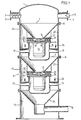
- FIG. 1 shows an embodiment of part of the direct heating equipment of the invention, that is to say of an impact mill used for combustibles in particularly fines 0 - 6 mm of coking, fatty or flaming coals, the ash and water contents of which are preferably limited to 10%.
- This impact crusher comprises, aligned along a vertical axis, an upper enclosure (1) provided with a supply duct (2) for wet solid fuel, with which is associated a doser (3) with worm screw, and a supply duct (4) for the primary gaseous oxidant, with which is associated a flow regulator (12) arranged so that this flow is sufficient to keep the pulverized fuel in turbulent suspension and insufficient to cause the ignition of the latter, two intermediate grinding chambers (5) each comprising a hopper (6) in the form of a truncated cone, the axis of which is situated on the above-mentioned vertical axis and the large base (7) of which is connected to the upper enclosure (1) , the small base (8) being located opposite a mobile grinding disc (9) propped up by a motor (-11) supported in the grinding chamber (5), the motor (11) and the disc ( 9) of each grinding chamber being coaxial with the corresponding hopper (6), the fuel crushed by each disc of br oyage (9) being projected onto the internal walls of an
- the impact crusher according to the invention also comprises a lower enclosure (14), connected to the casing (13) of the lower grinding enclosure (5), provided with a conduit (15) for discharging the crushed fuel and the primary oxidant towards the combustion.
- the drive motor (11) of each grinding disc (9) is fixed by means of a plate (24) in a sealed box (16), coaxial with the hopper (6), supported inside of the grinding jacket (13) by tubular arms (17) of which at least one is hollow to allow the supply of the motor, a seal (18) being provided on the box (16) at the location passage of the shaft (10) on which the grinding disc (9) is wedged.
- the grinding discs (9) comprise, according to the invention, on their face facing the small base (8) of the hopper (6), spindles (19) whose axes are parallel to that of the disc.
- Each grinding disc (9) cooperates with a corresponding ring (20) fixed to the periphery of the small base (8) of the hopper (6) coaxially with the grinding disc, the face of each fixed ring (20) facing the corresponding grinding disc (19) being provided with pins (21) whose axes are parallel to the pins (19) of the grinding disc (9).
- the lengths of the pins (19) are equal, as are the lengths of the pins (21), the distance separating the facing faces of the disc (9) and the corresponding ring (20) being greater to the length of the longest pins, the latter possibly being formed either by the pins (19) or by the pins (21), and less than the sum of the length of the pins (19) and the length of the pins (21 ), the pins (19) and (21) being regularly distributed in circles, the centers of which are located on the axis common to the disc (9) and the corresponding ring (20), so that the pins (21) of each ring (20) distributed over a circle are always located between the movable pins (19) of each corresponding grinding disc (9), distributed over two circles.
- These pins (19) and (21) may consist of elastic pins reinforced with steel, with spring, of very high hardness, which are immobilized in holes (22) bored or simply drilled or drilled in the disc or ring, without re-boring or other touch-up work. During their installation, the elastic pins are compressed and tighten strongly, by their elastic force, against the wall of the holes (22) This results in a high permanent resistance of the assembly, even during percussive and variable loads. In addition, these elastic pins are very economical and easily interchangeable.
- the grinding pins (19) and (21) can also be pierced with holes of the same diameter as the holes (22), the pins being in this case fixed to the disc or the ring by elastic pins.
- the pins (19) and (21) can also be fixed in the bored holes (22) by mechanical or hydraulic expansion, or under the effect of the explosion of a low internal load or by brazing or welding. It will also be noted that the pin grinding discs and the pin rings can each be made in one piece, for example by casting, forging, sintering, machining or any other suitable process. It is also possible according to the invention, to remove the fixed pins (21) on the rings (20), the movable pins (19) then being regularly distributed on the disk along radii of the latter and at short distances from each other, so as to form close impact surfaces.
- the wet solid fuel in turbulent suspension in the primary gaseous oxidizer enters through the hopper (6) in the form of a truncated cone and passes through the opening formed by its small base (8) in the space between the fixed ring (20) and the movable disc (9), where it is projected by centrifugal force.
- the fuel grains are sprayed by percussion and swirling between, on the one hand, the rotating (19) and fixed (21) spindles and, on the other hand, between the outer row of rotating spindles (19) and the shield inside (23) of the envelope (13).
- Oxidant entrainment the absence of fixed selectors, such as grids or louvers, the absence of movable selectors, such as rotating arms or paddlewheels, eliminate any increase in the local concentration of solids and, therefore, avoid clogging by agglomeration or bonding of wet particles.
- all other conditions remaining equal the reduction in the average diameter of the fuel grains increases with the number of successive grinding chambers (5) and with the speed of rotation of the grinding discs (9).
- the mixture of finely pulverized wet fuel and primary oxidizer after passing from the first grinding chamber to the second grinding chamber according to the arrows (25), is drawn into the hopper (26) in the form of a truncated cone of the 'lower enclosure (14), and is discharged through the conduit (15), fixed to the latter, to the burner.
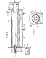
- FIGS 2 and 3 show another embodiment of the grinding apparatus of the invention, which can be used in place of the impact crusher in the direct heating equipment of the invention, namely a burner balls for solid fuels with a water content of the order of 4 to 50% of the mixture.
- the ball mill comprises a cylindrical drum (30) whose length is substantially greater than the diameter, as well as a support box (31) of the drum arranged so that the axis of the drum is arranged horizontally, this box (31) forming a cylindrical cradle (32) which surrounds the lateral face (33) of the drum over substantially half of its periphery, circular flanges (34, 34a) being provided on the bases (35, 35a) of the drum and their radius being greater than radius of the cradle (32), the faces of the box (31) facing the lateral face (33) of the drum (30) and look of the circular flanges (34, 34a) being provided with perforations (36) constituting nozzles, to allow passage to pressurized air forming a cushion (37),
- the air for example clean air under a pressure of the order of 1000 mm of water, is introduced into the box (31) through the tube (51) and escapes through the multiple perforations (36) at high pressure drops, so as to support and guide the cylindrical drum (30) and the circular flanges (34, 34a), with the same pressure at all points.
- This feature of the invention allows the walls of the cylindrical drum (30), and possibly each of its bases (35, 35a), to be made of a material having a low coefficient of friction in the dry state and in the wet state.
- the cylindrical drum (30) is driven in rotation about its axis by a drive motor (38) with an axis parallel to the axis of the drum, by a toothed wheel (39) wedged on the shaft (40) of the motor and by a chain (41) attacking the toothing (41a) produced at the periphery of the flange (34) associated with the base of the drum.
- the balls (43) of the crusher arranged inside the drum (30), are of substantially spherical shape, of small diameter, of the order of 5 to 10 mm, and are made of a material of high specific weight and high resistance to wear by abrasion and friction. These are, for example, balls or balls of steel or chromium in cast iron, nickel-chromium, ceramic material or any other material meeting the above conditions.
- the opening (44) through which the fuel supply duct (42) opens into the drum is such that there is sufficient space (48) between the edges of the opening and the external face of the duct.
- the pulverized fuel and the primary oxidizer of the cylindrical drum (30) are brought to the combustion chamber by a fan (49) associated with the exhaust duct (46), this fan (49) making it possible to suck the primary oxidant gas to through the annular space (48) provided at the inlet, and through the annular space (50) provided at the outlet.
- the ball mill could also be supplied with solid fuel with a high water content, for example 30 to 50% of the mixture, so as to constitute a fluid and pumpable paste.
- the circulation of the pulverized fuel from the drum (30) to the combustion chamber would be done by a pump associated with the evacuation duct (46). The continuous water phase would then replace the primary gaseous oxidant in the grinding operation.
- the drive motor (38) and the toothed wheels (39, 41) are such that they make it possible to ensure the drum (30) a supercritical speed, that is to say greater than the speed limit for which the centrifugal force exerted on a grinding body, such as ball or ball, in its highest position, is equal and opposite to the force of gravity, so that instead of falling, this body follows a circular centrifugation path.
- a supercritical speed that is to say greater than the speed limit for which the centrifugal force exerted on a grinding body, such as ball or ball, in its highest position, is equal and opposite to the force of gravity, so that instead of falling, this body follows a circular centrifugation path.
- the coefficient of friction between the coating and the load is equal to 1, and grinding is only possible at subcritical speeds, where the balls cascade down the on top of each other with shock effects.
- the interior surface of the cylindrical drum (30) is perfectly smooth, the coefficient of friction between the drum and the load being significantly less than 1, the load itself being moderate. Grinding then becomes possible at supercritical speeds, or the balls roll intensely on each other with effects of attrition and compression. This results in a much more intense grinding effect and a significantly higher specific production than in conventional systems.
- the heating equipment of the invention also makes it possible to purify the combustion products or fumes discharged into the atmosphere.
- This objective is achieved by the simple addition to solid fuels at the inlet of the mill or to the combustion products of solid, liquid or gaseous fuels or even of fumes at the entry of the condensing heat recovery unit, of substances capable of fixing the harmful substances, such as sulfur and fly ash, for example neutralizing products, such as calcium carbonate, potassium carbonate, sodium carbonate or quicklime. More than 90% of the sulfites and sulfates formed by the reaction will thus go into solution or suspension in condensed water and will be evacuated to the sewer.
Landscapes
- Engineering & Computer Science (AREA)
- General Engineering & Computer Science (AREA)
- Food Science & Technology (AREA)
- Mechanical Engineering (AREA)
- Chemical & Material Sciences (AREA)
- Combustion & Propulsion (AREA)
- Solid Fuels And Fuel-Associated Substances (AREA)
- Disintegrating Or Milling (AREA)
- Luminescent Compositions (AREA)
- Polyesters Or Polycarbonates (AREA)
- Tunnel Furnaces (AREA)
Description
- La présente invention est relative à un équipement de chauffe directe par combustible, en particulier pour des installations, telles que générateurs d'eau chaude, de vapeur et de gaz chauds, fours de cuisson, sécheurs, comprenant notamment un brûleur, une chambre de combustion, un échangeur à haute température, une source de combustible solide humide, un broyeur pour broyer le combustible en amont de la chambre de combustion et des moyens pour introduire directement dans cette dernière, sans réduire sa teneur en eau, le combustible broyé en présence d'un fluide comburant primaire.
- L'inconvénient principal des équipements classiques de chauffe au charbon pulvérisé du type direct ou indirect, consiste en ce qu'il est nécessaire de sécher le combustible pour ramener l'humidité de celui-ci aux environs de 1 % et assurer ainsi la fluidité du produit. De plus, il s'avère également nécessaire dans ces équipements conus de réaliser les opérations de transport et de stockage intermédiaires du pulvérisé séché sous atmosphère d'azote pour limiter les risques d'explosion. Enfin, les produits de combustion ou buées, dans les équipements classiques, sont rejetés à l'atmosphère sans aucune épuration, ce qui s'avère extrêmement préjudiciable pour l'environnement.
- A cet égard, la demande de brevet WO n° 83/04085 de Sayler et White concerne un broyeur ventilé à percussion permettant de réaliser en un seul passage avec recyclages internes, des opérations de broyage ultrafin sur des particules de charbons ou autres combustibles solides en suspension dans un courant d'air à température ambiante, dont le débit en poids représente 10 à 30 % de l'air comburant total nécessaire. Cette demande de brevet revendique notamment la possibilité de traiter tous les combustibles solides humides, mais ne précise pas le point essentiel qui est la teneur maximale admissible en eau. En réalité, tous les broyeurs connus, du type ventilé à percussion, permettent le broyage de combustibles solides humides en suspension dans l'air à température ambiante, pour autant que la teneur en eau ne dépasse pas 1 à 4 % suivant les types. Au delà de cette limite, de graves inconvénients de collages, dépôts, bouchages, obstructions, puissances absorbées irrégulières et usures excessives rendent l'exploitation impossible. De plus, tous ces broyeurs du type ventilé à percussion, et notamment le broyeur de Sayler et White, comportent des moteurs extérieurs avec transmissions et présentent en général de grandes surfaces de déperdition.
- D'autre part, le brevet US-A-2 399 051 de Maxon et coll. concerne un broyeur à boulets en vitesses subcritiques de conception classique, mais équipé d'un dispositif spécial de classement granulométrique interne avec recyclage, évitant la sortie de particules trop grosses.
- L'invention a pour but de prévoir un équipement de chauffe directe par combustible, en particulier pour les installations, tel les que générateurs d'eau chaude, de vapeur et de gaz chauds, fours de cuisson, sécheurs, comprenant un brûleur, une chambre de combustion, un échangeur haute température, ainsi qu'un broyeur pour broyer ce combustible en amont de la chambre de combustion et des moyens pour introduire directement dans cette dernière, sans réduire sa teneur en eau, le combustible broyé en présence d'un fluide comburant primaire, ce broyeur étant à percussion et comprenant, alignées suivant un axe vertical, une enceinte supérieure munie d'un conduit d'alimentation en combustible auquel est associé un doseur, et d'un conduit d'amenée du comburant gazeux primaire, au moins une enceinte de broyage pourvue d'une enveloppe, et une enceinte inférieure pourvue d'un conduit d'évacuation du combustible broyé et du comburant primaire vers la chambre de combustion, remédiànt aux inconvénients des installations classiques, tout en permettant également d'épurer les produits de combustion ou buées rejetés à l'atmosphère. L'équipement de l'invention se révèle de plus extrêmement fiable, très sûr, fort simple et peu coûteux à la construction, en fonctionement et à l'entretien.
- A cet effet, selon l'invention, le conduit d'amenée du comburant gazeux primaire comprend un régulateur de débit agencé pour que ce débit soit suffisant au maintien en suspension turbulente du combustible pulvérisé et insuffisant pour provoquer l'inflammation de ce dernier et l'enceinte de broyage comprend une trémie en forme de tronc de cône dont l'axe est situé sur l'axe vertical susdit et dont la grande base est raccordée à l'enceinte supérieure précitée tandis que sa petite base est située en regard d'un disque de broyage calé sur l'arbre d'un moteur supporté dans l'enceinte de broyage, de manière a ce que lesdits moteur et disque soient coaxiaux à la trémie et que le combustible broyé par le disque soit projeté sur les parois internes de l'enveloppe présentée par l'enceinte de broyage et entourant la trémie, l'enceinte inférieure étant raccordée sur l'enveloppe de l'enceinte de broyage.
- Suivant un mode de réalisation avantageux de l'invention, le moteur d'entraînement du disque de broyage est fixé dans un caisson étanche, coaxial à la trémie, supporté à l'intérieur de l'enveloppe de broyage par des bras dont au moins un est creux pour permettre l'alimentation du moteur, une garniture d'étanchéité étant prévue sur ce caisson à l'endroit de passage de l'arbre sur lequel est calé le disque de broyage, ce disque de broyage comprenant sur sa face tournée vers la petite base de la trémie, des broches dont les axes sont parallèles à celui du disque.
- Suivant un mode de réalisation particulièrement avantageux de l'invention, le disque de broyage susdit coopère avec un anneau fixé à la périphérie de la petite base de la trémie coaxialement au disque de broyage, la face de cet anneau fixe tournée vers le disque de broyage étant garnie de broches dont les axes sont parallèles aux broches du disque de broyage, la distance séparant les faces tournées l'une vers l'autre du disque et de l'anneau étant supérieure à la longueur des broches les plus longues et inférieure à la somme de la longueur des broches du disque et de la longueur des broches de l'anneau, les broches du disque et de l'anneau étant régulièrement réparties suivant des cercles, dont les centres sont situés sur l'axe commun au disque et à l'anneau, de manière à ce que les broches fixes de l'anneau réparties sur un cercle soient toujours situées entre les broches mobiles du disque de broyage réparties sur deux cercles.
- Suivant une autre forme de réalisation de l'invention, le broyeur précité est constitué par un broyeur à boulets comprenant un tambour cylindrique dont la longueur est supérieure au diamètre, un caisson formant un berceau cylindrique qui entoure la face latérale du tambour sur une partie de son pourtour, des flasques circulaires étant prévus sur chaque base du tambour et leur rayon étant supérieur au rayon du berceau, les faces du caisson en regard de la face latérale du tambour et en regard des flasques étant perforées pour livrer passage à de l'air sous pression formant un coussin pour, d'une part, supporter le tambour et, d'autre part, maintenir ce dernier, grâce au coussin d'air entre le caisson et les flasques, immobile suivant une direction parallèle à son axe, des moyens étant prévus pour mettre et maintenir ledit caisson sous pression, des moyens d'entraînement agencés pour entraîner le tambour en rotation autour de son axe, un conduit d'amenée du combustible, fixe par rapport au tambour et coaxial à ce dernier, débouchant à l'intérieur du tambour par une ouverture réalisée dans une des bases de ce dernier, un doseur agencé dans ledit conduit d'amenée, un conduit d'évacuation du combustible pulvérisé, fixe par rapport au tambour et coaxial à ce dernier, débouchant à l'intérieur dudit tambour à travers une ouverture réalisée dans l'autre base de celui-ci et des moyens pour faire circuler le combustible pulvérisé et le comburant primaire du tambour vers la chambre de combustion.
- Suivant une forme de réalisation particulièrement avantageuse de l'invention, au moins l'ouverture susdite à travers laquelle le conduit d'amenée du combustible débouche dans le tambour est telle qu'il subsiste, entre les bords de l'ouverture et la face externe du conduit, un espace suffisant pour le passage d'un comburant primaire gazeux, les moyens précités pour faire circuler le combustible pulvérisé et le comburant primaire du tambour vers la chambre de combustion étant constitués par un ventilateur associé au conduit d'évacuation susdit, ce ventilateur étant tel qu'il puisse aspirer le comburant primaire gazeux à travers l'espace précité subsistant autour du conduit d'amenée du combustible.
- Outre les avantages précités, comme on l'a déjà mentionné, l'équipement de l'invention permet également d'épurer les produits de combustion ou buées rejetés à l'atmosphère, par l'introduction soit à l'endroit de broyage du combustible, soit à l'endroit de récupération de la chaleur des gaz de combustion, de substances capables de fixer les matières nocives, telles que le soufre et les cendres volantes, comme, par exemple, des produits neutralisants, tels que le carbonate de calcium, le carbonate de potassium, le carbonate de sodium ou la chaux vive.
- D'autres détails et particularités de l'invention ressortiront de la description des dessins annexés au présent mémoire, qui représentent, à titre d'exemples non limitatifs, diverses formes particulières de l'objet de l'invention.
- La figure 1 est une figure schématique, en élévation et en coupe, montrant une forme de réalisation de broyeur à percussion de l'équipement de chauffe directe de l'invention.
- La figure 2 est une figure schématique, en élévation et en coupe, montrant une forme de réalisation de broyeur à boulets de l'équipement de chauffe directe de l'invention.
- La figure 3 est une vue en coupe suivant la ligne 111 - 111 de la figure 2.
- Dans les différentes figures, les mêmes notations de référence désignent des éléments identiques ou analogues.
- La figure 1, comme on vient de le préciser, montre une forme de réalisation d'une partie de l'équipement de chauffe directe de l'invention, c'est-à-dire d'un broyeur à percussion utilisé pour des combustibles en particulier des fines 0 - 6 mm de charbons cokéfiants, gras ou flambants, dont les teneurs en cendres et en eau sont de préférence limitées à 10 %. Ce broyeur à percussion comprend, alignées suivant un axe vertical, une enceinte supérieure (1) munie d'un conduit d'alimentation (2) en combustible solide humide, auquel est associé un doseur (3) à vis sans fin, et d'un conduit d'amenée (4) du comburant gazeux primaire, auquel est associé un régulateur de débit (12) agencé pour que ce débit soit suffisant pour maintenir en suspension turbulente le combustible pulvérisé et insuffisant pour provoquer l'inflammation de ce dernier, deux enceintes de broyage intermédiaires (5) comprenant chacune une trémie (6) en forme de tronc de cône dont l'axe est situé sur l'axe vertical précité et dont la grande base (7) est raccordée à l'enceinte supérieure (1), la petite base (8) étant située en regard d'un disque de broyage mobile (9) calé d'un moteur (-11) supporté dans l'enceinte de broyage (5), le moteur (11) et le disque (9) de chaque enceinte de broyage étant coaxiaux à la trémie correspondante (6), le combustible broyé par chaque disque de broyage (9) étant projeté sur les parois internes d'une enveloppe (13) représentée par chaque enceinte de broyage (5), entourant la trémie, les parois internes étant chacune garnie d'un blindage (23) réalisé en un matériau présentant une haute résistance à l'usure. Le broyeur à percussion selon l'invention comprend également une enceinte inférieure (14), raccordée sur l'enveloppe (13) de l'enceinte de broyage inférieure (5), pourvue d'un conduit (15) d'évacuation du combustible broyé et du comburant primaire vers la chambre de combustion. Le moteur d'entraînement (11) de chaque disque de broyage (9) est fixé par l'intermédiaire d'un plateau (24) dans un caisson (16) étanche, coaxial à la trémie (6), supporté à l'intérieur de l'enveloppe de broyage (13) par des bras tubulaires (17) dont au moins un est creux pour permettre l'alimentation du moteur, une garniture d'étanchéité (18) étant prévue sur le caisson (16) à l'endroit de passage de l'arbre (10) sur lequel est calé le disque de broyage (9).
- Les disques de broyage (9) comprennent, suivant l'invention, sur leur face tournée vers la petite base (8) de la trémie (6), des broches (19) dont les axes sont parallèles à celui du disque.
- Chaque disque de broyage (9) coopère avec un anneau (20) correspondant fixé à la périphérie de la petite base (8) de la trémie (6) coaxialement au disque de broyage, la face de chaque anneau fixe (20) tournée vers le disque de broyage correspondant (19) étant garnie de broches (21) dont les axes sont parallèles aux broches (19) du disque de broyage (9). Les longueurs des broches (19) sont égales, de même que les longueurs des broches (21), la distance séparant les faces tournées l'une vers l'autre du disque (9) et de l'anneau (20) correspondant étant supérieure à la longueur des broches les plus longues, ces dernières pouvant être constituées soit par les broches (19) soit par les broches (21), et inférieure à la somme de la longueur des broches (19) et de la longueur des broches (21), les broches (19) et (21) étant régulièrement réparties suivant des cercles, dont les centres sont situés sur l'axe commun au disque (9) et à l'anneau correspondant (20), de manière à ce que les broches (21) de chaque anneau (20) répartie sur un cercle soient toujours situées entre les broches mobiles (19) de chaque disque de broyage (9) correspondant, réparties sur deux cercles. Ces broches (19) et (21) peuvent être constituées de broches élastiques renforcées en acier, à ressort, de très grande dureté, qui sont immobilisées dans des trous (22) alésés ou simplement percés ou forés dans le disque ou l'anneau, sans réalésage ni autre travail de retouche. Lors de leur mise en place, les broches élastiques sont comprimées et serrent fortement, par leur force élastique, contre la paroi des trous (22) Il en résulte une haute résistance permanente de l'assemblage, même lors de charges percutantes et variables. De plus, ces broches élastiques sont très économiques et facilement interchangeables. Les broches de broyage (19) et (21) peuvent également être percées de trous de même diamètre que les trous (22), les broches étant dans ce cas fixées sur le disque ou l'anneau par des goupilles élastiques. Les broches (19) et (21) peuvent également être fixées dans les trous alésés (22) par expansion mécanique ou hydraulique, ou sous l'effet de l'explosion d'une faible charge intérieure ou encore par brasage ou soudure. On notera également que les disques de broyage à broches et les anneaux à broches peuvent être réalisés chacun en une seule pièce, par exemple par coulée, forgeage, frittage, usinage ou tout autre procédé approprié. On pourra également suivant l'invention, supprimer les broches fixes (21) sur les anneaux (20), les broches mobiles (19) étant alors régulièrement réparties sur le disque suivant des rayons de ce dernier et à faibles distances les unes des autres, de façon à former des surfaces d'imact rapprochées.
- Dans chacune des enceintes de broyage (5), le combustible solide humide en suspension turbulente dans le comburant primaire gazeux pénètre par la trémie (6) en forme de tronc de cône et passe par l'ouverture constituée par sa petite base (8) dans l'espace compris entre l'anneau fixe (20) et le disque mobile (9), où il est projeté par la force centrifuge. La pulvérisation des grains de combustible est assurée par percussion et tourbillonnement entre, d'une part, les broches tournantes (19) et fixes (21) et, d'autre part, entre la rangée extérieure de broches tournantes (19) et le blindage intérieur (23) de l'enveloppe (13). L'entraînement par le comburant, l'absence de sélecteurs fixes, tels que grilles ou ventelles l'absence de sélecteurs mobiles, tels que bras tournants ou roues à aubes, éliminent toute augmentation de la concentration locale en solides et, par conséquent, évitent le colmatage par agglomération ou collage des particules humides. D'autre part, toutes autres conditions restant égales, la réduction du diamètre moyen des grains de combustible augmente avec le nombre d'enceintes de broyage (5) successives et avec la vitesse de rotation des disques de broyage (9). Le mélange de combustible humide finement pulvérisé et de comburant primaire, après être passé de la première enceinte de broyage vers la seconde enceinte de broyage suivant les flèches (25), est entraîné dans la trémie (26) en forme de tronc de cône de l'enceinte inférieure (14), et est évacué par le conduit (15), fixé à cette dernière, vers le brûleur.
- Les figures 2 et 3 représentent une autre forme de réalisation d'appareil de broyage de l'invention, que l'on peut utiliser à la place du broyeur à percussion dans l'équipement de chauffe directe de l'invention, à savoir un brûleur à boulets pour combustibles solides dont la teneur en eau est de l'ordre de 4 à 50 % du mélange. Le broyeur a boulets comprend un tambour cylindrique (30) dont la longueur est sensiblement supérieure au diamètre, ainsi qu'un caisson de support (31) du tambour agencé pour que l'axe du tambour soit disposé horizontalement, ce caisson (31) formant un berceau cylindrique (32) qui entoure la face latérale (33) du tambour sur sensiblement la moitié de son pourtour, des flasques circulaires (34, 34a) étant prévus sur les bases (35, 35a) du tambour et leur rayon étant supérieur au rayon du berceau (32), les faces du caisson (31) en regard de la face latérale (33) du tambour (30) et en regard des flasques circulaires (34, 34a) étant pourvues de perforations (36) constituant des tuyères, pour livrer passage à de l'air sous pression formant un coussin (37), ce coussin d'air (37) servant, d'une part, à supporter le tambour (30) et, d'autre part, à maintenir ce dernier, entre le caisson (31) et les flasques circulaires (34, 34a) suivant une direction parallèle à son axe, des moyens (non représentés) étant prévus pour mettre et maintenir le caisson (31) sous pression. L'air, par exemple de l'air propre sous une pression de l'ordre de 1000 mm d'eau, est introduit dans le caisson (31) par la tubulure (51) et s'échappe par les multiples perforations (36) à fortes pertes de charge, de manière à supporter et à guider le tambour cylindrique (30) et les flasques circulaires (34, 34a), avec la même pression en tous points. Cette particularité de l'invention permet de réaliser les parois du tambour cylindrique (30), et éventuellement chacune de ses bases (35, 35a), en un matériau présentant un faible coefficient de friction à l'état sec et à l'état humide, ainsi qu'une grande résistance à l'usure par abrasion et frottement, matériau qui peut être constitué, par exemple, d'une polyoléfine de haut poids moléculaire, de préférence en polyéthylène ou polybutylène, de polyuréthanne, d'acier ou de fonte coulés par centrifugation et trempés, de porcelaine, de silice fondue, de verre ou de toute autre matière répondant aux propriétés susmentionnées. Le tambour cylindrique (30) est entraîné en rotation autour de son axe par un moteur d'entraînement (38) d'axe parallèle à l'axe du tambour, par une roue dentée (39) calée sur l'arbre (40) du moteur et par une chaîne (41) attaquant la denture (41a) réalisée à la périphérie du flasque (34) associé à la base du tambour. Les boulets (43) du broyeur disposés à l'intérieur du tambour (30), sont de forme sensiblement sphérique, de faible diamètre, de l'ordre de 5 à 10 mm, et sont réalisés en une matière de poids spécifique élevé et de haute résistance à l'usure par abrasion et frottement. Il s'agit, par exemple, de billes ou boulets en acier ou chrome en fonte, au nickel- chrome, en matière céramique ou en toute autre matière répondant aux conditions ci-dessus. Un conduit (42) d'amenée du combustible solide humide, fixe par rapport au tambour et coaxial à ce dernier, débouche à l'intérieur du tambour par une ouverture (44) réalisée dans la base (35) de ce dernier, l'alimentation en combustible se faisant au moyen d'un doseur (45), tel que vis sans fin, agencé dans le conduit d'amenée (42), l'évacuation du combustible pulvérisé se faisant au moyen d'un conduit (46) fixe par rapport au tambour (30) et coaxial à ce dernier, débouchant à l'intérieur du tambour (30) à travers une ouverture (47) et réalisée dans la base (35a) de celui-ci. L'ouverture (44) à travers laquelle le conduit d'amenée du combustible (42) débouche dans le tambour est telle qu'il subsiste, entre les bords de l'ouverture et la face externe du conduit, un espace (48) suffisant pour le passage d'un comburant primaire gazeux. Le combustible pulvérisé et le comburant primaire du tambour cylindrique (30) sont amenés à la chambre de combustion par un ventilateur (49) associé au conduit d'évacuation (46), ce ventilateur (49) permettant d'aspirer le comburant primaire gazeux à travers l'espace annulaire (48) prévu à l'entrée, et à travers l'espace annulaire (50), prévu à la sortie. Le broyeur à boulets pourrait également être alimenté en combustible solide à forte teneur en eau, par exemple 30 à 50 % du mélange, de manière à constituer une pâte fluide et pompable. Dans ce cas, la circulation du combustible pulvérisé du tambour (30) vers la chambre de combustion se ferait par une pompe associée au conduit d'évacuation (46). La phase continue eau remplacerait alors le comburant gazeux primaire dans l'opération de broyage.
- Suivant l'invention, le moteur d'entraînement (38) et les roues dentées (39, 41) sont tels qu'ils permettent d'assurer au tambour (30) une vitesse supercritique, c'est-à-dire supérieure à la vitesse limite pour laquelle la force centrifuge exercée sur un corps broyant, tel que boulet ou bille, dans sa position la plus haute, est égale et opposée à la force de gravité, de telle sorte qu'au lieu de retomber, ce corps suive une trajectoire circulaire de centrifugation. Dans tous les broyeurs à boulets classiques équipés de revêtements intérieurs crénélés ou ondulés, le coefficient de friction entre le revêtement et la charge est égal à 1, et le broyage n'est possible qu'en vitesses subcritiques, où les billes retombent en cascade les unes sur les autres avec effets de choc. Au contraire, dans le broyeur à boulets de la présente invention, la surface intérieure du tambour cylindrique (30) est parfaitement lisse, le coefficient de friction entre le tambour et la charge étant nettement inférieur à 1, la charge étant elle-même modérée. Le broyage devient alors possible en vitesses supercritiques, ou les billes roulent intensément les unes sur les autres avec des effets d'attrition et de compression. Il en résulte un effet de broyage beaucoup plus intense et une production spécifique nettement plus élevée que dans les systèmes classiques.
- Un autre avantage du broyeur à boulets de l'invention est de permettre la réalisation d'un broyeur représentant un rapport longueur- diamètre beaucoup plus élevé que les systèmes classiques, avec un grand rapport de réduction de dimension du grain moyen. Le broyeur à boulets de l'invention permet donc de réaliser un broyage fin ou ultra-fin en un seul passage, sans aucun tamis ni sélecteur extérieur ni recyclage de produit -trop gros, et avec une consommation minimale d'énergie. Toutes autres conditions égales, des essais réalisés sur le broyeur à boulets de l'invention ont montré que la production de matière pulvérisée était donnée par la relation suivante:

- P = production de charbon pulvérisé en kg/hre
- K = constante, fonction des matières en présence
- D = diamètre intérieur du tambour lisse en m
- L = longueur intérieure du tambour lisse en m
- N = vitesse de rotation du tambour lisse en tours/minute.
- Ainsi qu'on l'a déjà précisé précédemment, l'équipement de chauffe de l'invention permet également d'épurer les produits de combustion ou buées rejetés à l'atmosphère. Cet objectif est atteint par la simple addition aux combustibles solides à l'entrée du broyeur ou aux produits de combustion de combustibles solides, liquides ou gazeux ou encore de buées à l'entrée du récupérateur de chaleur à condensation, de substances capables de fixer les matières nocives, telles que le soufre et les cendres volantes, par exemple des produits neutralisants, tels que le carbonate de calcium, le carbonate de potassium, le carbonate de sodium ou de la chaux vive. Plus de 90 % des sulfites et sulfates formés par la réation passeront ainsi en solution ou suspension dans l'eau condensée et seront évacués à l'égout.
Claims (15)
Priority Applications (1)
| Application Number | Priority Date | Filing Date | Title |
|---|---|---|---|
| AT85870059T ATE45798T1 (de) | 1984-05-03 | 1985-04-29 | Vorrichtung zur direkten beheizung. |
Applications Claiming Priority (2)
| Application Number | Priority Date | Filing Date | Title |
|---|---|---|---|
| BE0/212862A BE899562A (fr) | 1984-05-03 | 1984-05-03 | Procede et equipement de chauffe directe. |
| BE212862 | 1984-05-03 |
Publications (2)
| Publication Number | Publication Date |
|---|---|
| EP0165224A1 EP0165224A1 (fr) | 1985-12-18 |
| EP0165224B1 true EP0165224B1 (fr) | 1989-08-23 |
Family
ID=3843755
Family Applications (1)
| Application Number | Title | Priority Date | Filing Date |
|---|---|---|---|
| EP85870059A Expired EP0165224B1 (fr) | 1984-05-03 | 1985-04-29 | Equipement de chauffe directe |
Country Status (4)
| Country | Link |
|---|---|
| US (1) | US4734960A (fr) |
| EP (1) | EP0165224B1 (fr) |
| AT (1) | ATE45798T1 (fr) |
| DE (1) | DE3572528D1 (fr) |
Families Citing this family (10)
| Publication number | Priority date | Publication date | Assignee | Title |
|---|---|---|---|---|
| FR2678047B1 (fr) * | 1991-06-18 | 1993-10-15 | Equip Technic | Dispositif de traitement des fumees chaudes et polluees, notamment acides, provenant de la combustion du fuel dans une chaudiere industrielle ou de chauffage urbain. |
| NL9302081A (nl) * | 1993-11-30 | 1995-06-16 | Gastec Nv | Werkwijze voor het verwijderen van elementaire zwavel uit een gasstroom. |
| US5727741A (en) * | 1996-07-19 | 1998-03-17 | Custom Machinery Llc | Pulverizing assembly |
| NZ545960A (en) | 2006-03-15 | 2008-04-30 | Environmental Decontamination | Milling apparatus |
| US20080230641A1 (en) * | 2007-03-23 | 2008-09-25 | Dynacorp Engineering Inc. | Staged cascade mill |
| US20100001110A1 (en) * | 2008-07-03 | 2010-01-07 | Imperial Technologies, Inc. | Material breaker |
| EP2322279B1 (fr) * | 2009-11-17 | 2016-05-11 | Biohyst Overseas Sagl | Dispositif de broyage et de séparation de biomasse |
| JP2015174046A (ja) * | 2014-03-17 | 2015-10-05 | Jfeマテリアル株式会社 | 粉末冶金用クロムの製造方法 |
| US10493464B2 (en) * | 2014-12-18 | 2019-12-03 | Aaron Engineered Process Equipment, Inc. | Rotary mill |
| RU2630450C1 (ru) * | 2016-06-29 | 2017-09-08 | федеральное государственное бюджетное образовательное учреждение высшего образования "Белгородский государственный технологический университет им. В.Г. Шухова" | Дезинтегратор |
Family Cites Families (25)
| Publication number | Priority date | Publication date | Assignee | Title |
|---|---|---|---|---|
| BE379682A (fr) * | ||||
| FR554914A (fr) * | 1921-12-06 | 1923-06-19 | Dispositif pulvérisateur pour combustible solide | |
| FR573994A (fr) * | 1923-11-08 | 1924-07-03 | Perfectionnements dans le traitement de combustible pulvérisé pour chaudières ou autres foyers | |
| US1808509A (en) * | 1928-06-20 | 1931-06-02 | American Encaustic Tiling Comp | Clay disintegrator |
| GB441215A (en) * | 1934-08-27 | 1936-01-15 | S O S Patents Company Ltd | Improvements relating to grinding, blending and emulsifying machines |
| FR52754E (fr) * | 1943-02-16 | 1945-06-01 | Désintégrateur | |
| US2468389A (en) * | 1943-07-31 | 1949-04-26 | George A Auer | Mechanical mixer |
| US2399051A (en) * | 1943-09-06 | 1946-04-23 | Allis Chalmers Mfg Co | Air swept ball mill |
| DE841381C (de) * | 1944-09-28 | 1952-06-16 | Kreiselgeraete G M B H | Reibungsfreies Druckpolsterlager |
| BE507123A (fr) * | 1950-11-21 | |||
| GB726715A (en) * | 1953-04-16 | 1955-03-23 | Herbert Ltd A | Pulverising machines |
| CH323402A (fr) * | 1954-01-29 | 1957-07-31 | Kek Limited | Machine destinée à la mouture, à la pulvérisation et au mélange de matériaux |
| US2882149A (en) * | 1955-04-14 | 1959-04-14 | Willems Peter | Flow apparatus for the continuous physical and/or chemical treatment of substances |
| DE1152003B (de) * | 1955-04-14 | 1963-07-25 | Forsch Inst Prof Ing Chem Pete | Vorrichtung zum Zerkleinern, Dispergieren und Homogenisieren von Stoffgemischen sowie zur Durchfuehrung chemischer Prozesse im stetigen Durchlauf-verfahren |
| US3049857A (en) * | 1960-03-10 | 1962-08-21 | John D Shaw | Comminutor |
| GB1002877A (en) * | 1964-03-26 | 1965-09-02 | Sturtevant Mill Co | Method and machine for pin grinding |
| FR1594660A (fr) * | 1968-10-14 | 1970-06-08 | ||
| US3887249A (en) * | 1974-04-08 | 1975-06-03 | Allis Chalmers | Journal bearing for supporting both radial loads and axial thrust loads |
| US4054292A (en) * | 1976-12-16 | 1977-10-18 | Union Carbide Corporation | Gas seal for rotating grinding mill having peripheral discharge |
| US4284609A (en) * | 1977-07-11 | 1981-08-18 | Quad Environmental Technologies Corp. | Condensation cleaning of particulate laden gases |
| DE2836440A1 (de) * | 1978-08-19 | 1980-03-06 | Ruhrchemie Ag | Verfahren zur herstellung einer kohle- wasser-suspension, die zum einsatz in eine kohlevergasung unter erhoehtem druck geeignet ist |
| US4244529A (en) * | 1979-05-07 | 1981-01-13 | The Cleveland Cliffs Iron Company | Inerting of pulverizing mills for combustible materials |
| US4426042A (en) * | 1980-10-16 | 1984-01-17 | Mineral Processing Systems, Inc. | Method of shredding solid waste |
| DE3134297C2 (de) * | 1981-08-29 | 1984-02-09 | M.A.N. Maschinenfabrik Augsburg-Nürnberg AG, 4200 Oberhausen | Vorrichtung zum Zuführen naßvermahlener, relativ stark wasserangereicherter Kohle zum Brenner eines Kohledruckvergasungsreaktors |
| AU566176B2 (en) * | 1982-05-14 | 1987-10-08 | T.A.S. Inc. | Pulverized solid fuel burning apparatus |
-
1985
- 1985-04-26 US US06/727,662 patent/US4734960A/en not_active Expired - Fee Related
- 1985-04-29 AT AT85870059T patent/ATE45798T1/de active
- 1985-04-29 EP EP85870059A patent/EP0165224B1/fr not_active Expired
- 1985-04-29 DE DE8585870059T patent/DE3572528D1/de not_active Expired
Non-Patent Citations (1)
| Title |
|---|
| "SCIENCE ET TECHNIQUE" vol.nos 7,8,9,10/1944 et 1,3,4,11,12/1945 * |
Also Published As
| Publication number | Publication date |
|---|---|
| US4734960A (en) | 1988-04-05 |
| EP0165224A1 (fr) | 1985-12-18 |
| ATE45798T1 (de) | 1989-09-15 |
| DE3572528D1 (en) | 1989-09-28 |
Similar Documents
| Publication | Publication Date | Title |
|---|---|---|
| EP1846721B1 (fr) | Four pour la fusion de verre | |
| EP0165224A1 (fr) | Equipement de chauffe directe | |
| EP0006805B1 (fr) | Appareil de distribution de particules solides | |
| FR2584175A1 (fr) | Procede et refroidisseur fixe pour refroidir une matiere granulaire | |
| CH618781A5 (fr) | Installation de combustion de matiere divisees, notamment de dechets | |
| FR2842584A1 (fr) | Procede et dispositif pour augmenter la stabilite de la flamme dans les foyers au charbon pulverise | |
| EP0391768B1 (fr) | Tambour sécheur et enrobeur pour la préparation de produits enrobés bitumineux comportant un brûleur perfectionné | |
| EP2106294B1 (fr) | Appareil de sélection granulométrique et/ou de séchage de matière | |
| EP0039270B1 (fr) | Installation pour le traitement par séchage et/ou chauffage et broyage d'un matériau granuleux | |
| EP0675324A1 (fr) | Système d'injection d'air dans un foyer ou une chambre de combustion et installation d'incinération de biomasse ou de déchets industriels équipée de ce système | |
| EP0485255B1 (fr) | Procédé et dispositif de production d'un combustible solide à partir de déchets combustibles | |
| FR2565992A1 (fr) | Procede et installation pour la combustion partielle et la gazeification de matieres carbonees, au moyen d'un generateur de plasma | |
| EP1247046B1 (fr) | Methode et dispositif d'auto-combustion de dechets organiques graisseux comportant un foyer a chauffe tangentielle | |
| FR2464749A1 (fr) | ||
| BE899562A (fr) | Procede et equipement de chauffe directe. | |
| FR2493186A1 (fr) | Centrifugeur avec dispositif anti-abrasion, pour la separation de particules en suspension dans un fluide gazeux | |
| EP1181101B1 (fr) | Broyeur a boulets | |
| CH655944A5 (fr) | Appareil pour la calcination du coke. | |
| FR2463360A1 (fr) | Installation de combustion a combustibles solides | |
| EP0094307B1 (fr) | Perfectionnements aux broyeurs à jets | |
| JPS596701B2 (ja) | スラリ−から微粉材料を製造する方法 | |
| FR2458752A1 (fr) | Procede d'incineration de dechets et incinerateur permettant la mise en oeuvre de ce procede | |
| EP3370877B1 (fr) | Broyeur pendulaire perfectionné | |
| FR2481783A1 (fr) | ||
| FR2468836A1 (fr) | Procedes et appareils pour bruler des combustibles solides divises de faible granulometrie |
Legal Events
| Date | Code | Title | Description |
|---|---|---|---|
| PUAI | Public reference made under article 153(3) epc to a published international application that has entered the european phase |
Free format text: ORIGINAL CODE: 0009012 |
|
| AK | Designated contracting states |
Designated state(s): AT CH DE FR GB IT LI LU NL SE |
|
| 17P | Request for examination filed |
Effective date: 19860603 |
|
| 17Q | First examination report despatched |
Effective date: 19870126 |
|
| ITF | It: translation for a ep patent filed | ||
| GRAA | (expected) grant |
Free format text: ORIGINAL CODE: 0009210 |
|
| AK | Designated contracting states |
Kind code of ref document: B1 Designated state(s): AT CH DE FR GB IT LI LU NL SE |
|
| PG25 | Lapsed in a contracting state [announced via postgrant information from national office to epo] |
Ref country code: SE Effective date: 19890823 Ref country code: NL Effective date: 19890823 Ref country code: GB Effective date: 19890823 Ref country code: AT Effective date: 19890823 |
|
| REF | Corresponds to: |
Ref document number: 45798 Country of ref document: AT Date of ref document: 19890915 Kind code of ref document: T |
|
| REF | Corresponds to: |
Ref document number: 3572528 Country of ref document: DE Date of ref document: 19890928 |
|
| NLV1 | Nl: lapsed or annulled due to failure to fulfill the requirements of art. 29p and 29m of the patents act | ||
| GBV | Gb: ep patent (uk) treated as always having been void in accordance with gb section 77(7)/1977 [no translation filed] | ||
| PLBE | No opposition filed within time limit |
Free format text: ORIGINAL CODE: 0009261 |
|
| STAA | Information on the status of an ep patent application or granted ep patent |
Free format text: STATUS: NO OPPOSITION FILED WITHIN TIME LIMIT |
|
| 26N | No opposition filed | ||
| PGFP | Annual fee paid to national office [announced via postgrant information from national office to epo] |
Ref country code: LU Payment date: 19920429 Year of fee payment: 8 |
|
| ITTA | It: last paid annual fee | ||
| EPTA | Lu: last paid annual fee | ||
| PG25 | Lapsed in a contracting state [announced via postgrant information from national office to epo] |
Ref country code: LU Free format text: LAPSE BECAUSE OF NON-PAYMENT OF DUE FEES Effective date: 19930429 |
|
| PGFP | Annual fee paid to national office [announced via postgrant information from national office to epo] |
Ref country code: FR Payment date: 19930430 Year of fee payment: 9 |
|
| PGFP | Annual fee paid to national office [announced via postgrant information from national office to epo] |
Ref country code: CH Payment date: 19930505 Year of fee payment: 9 |
|
| PGFP | Annual fee paid to national office [announced via postgrant information from national office to epo] |
Ref country code: DE Payment date: 19930830 Year of fee payment: 9 |
|
| PG25 | Lapsed in a contracting state [announced via postgrant information from national office to epo] |
Ref country code: LI Effective date: 19940430 Ref country code: CH Effective date: 19940430 |
|
| PG25 | Lapsed in a contracting state [announced via postgrant information from national office to epo] |
Ref country code: FR Effective date: 19941229 |
|
| REG | Reference to a national code |
Ref country code: CH Ref legal event code: PL |
|
| PG25 | Lapsed in a contracting state [announced via postgrant information from national office to epo] |
Ref country code: DE Effective date: 19950103 |
|
| REG | Reference to a national code |
Ref country code: FR Ref legal event code: ST |