EP0165349B1 - Mechanismus zur Handhabung von Karten bei einem selbsttätigen Bankschalter - Google Patents
Mechanismus zur Handhabung von Karten bei einem selbsttätigen Bankschalter Download PDFInfo
- Publication number
- EP0165349B1 EP0165349B1 EP84304216A EP84304216A EP0165349B1 EP 0165349 B1 EP0165349 B1 EP 0165349B1 EP 84304216 A EP84304216 A EP 84304216A EP 84304216 A EP84304216 A EP 84304216A EP 0165349 B1 EP0165349 B1 EP 0165349B1
- Authority
- EP
- European Patent Office
- Prior art keywords
- card
- cam
- bale
- slot
- pin
- Prior art date
- Legal status (The legal status is an assumption and is not a legal conclusion. Google has not performed a legal analysis and makes no representation as to the accuracy of the status listed.)
- Expired
Links
Images


Classifications
-
- G—PHYSICS
- G07—CHECKING-DEVICES
- G07F—COIN-FREED OR LIKE APPARATUS
- G07F19/00—Complete banking systems; Coded card-freed arrangements adapted for dispensing or receiving monies or the like and posting such transactions to existing accounts, e.g. automatic teller machines
- G07F19/20—Automatic teller machines [ATMs]
-
- B—PERFORMING OPERATIONS; TRANSPORTING
- B65—CONVEYING; PACKING; STORING; HANDLING THIN OR FILAMENTARY MATERIAL
- B65B—MACHINES, APPARATUS OR DEVICES FOR, OR METHODS OF, PACKAGING ARTICLES OR MATERIALS; UNPACKING
- B65B69/00—Unpacking of articles or materials, not otherwise provided for
- B65B69/0008—Opening and emptying bags
-
- G—PHYSICS
- G06—COMPUTING OR CALCULATING; COUNTING
- G06K—GRAPHICAL DATA READING; PRESENTATION OF DATA; RECORD CARRIERS; HANDLING RECORD CARRIERS
- G06K13/00—Conveying record carriers from one station to another, e.g. from stack to punching mechanism
- G06K13/02—Conveying record carriers from one station to another, e.g. from stack to punching mechanism the record carrier having longitudinal dimension comparable with transverse dimension, e.g. punched card
- G06K13/06—Guiding cards; Checking correct operation of card-conveying mechanisms
- G06K13/063—Aligning cards
-
- G—PHYSICS
- G06—COMPUTING OR CALCULATING; COUNTING
- G06K—GRAPHICAL DATA READING; PRESENTATION OF DATA; RECORD CARRIERS; HANDLING RECORD CARRIERS
- G06K13/00—Conveying record carriers from one station to another, e.g. from stack to punching mechanism
- G06K13/02—Conveying record carriers from one station to another, e.g. from stack to punching mechanism the record carrier having longitudinal dimension comparable with transverse dimension, e.g. punched card
- G06K13/08—Feeding or discharging cards
-
- G—PHYSICS
- G07—CHECKING-DEVICES
- G07F—COIN-FREED OR LIKE APPARATUS
- G07F19/00—Complete banking systems; Coded card-freed arrangements adapted for dispensing or receiving monies or the like and posting such transactions to existing accounts, e.g. automatic teller machines
- G07F19/20—Automatic teller machines [ATMs]
- G07F19/201—Accessories of ATMs
-
- G—PHYSICS
- G07—CHECKING-DEVICES
- G07F—COIN-FREED OR LIKE APPARATUS
- G07F7/00—Mechanisms actuated by objects other than coins to free or to actuate vending, hiring, coin or paper currency dispensing or refunding apparatus
- G07F7/005—Details or accessories
Definitions
- the present invention relates to a card handling mechanism.
- the invention particularly relates to such a mechanism for use in reading a card presented to an autoteller. More particularly it relates to a card reading and handling mechanism for use in an autoteller where the card remains visible to the user at all times.
- the user presents his card to the autoteller by means of a slot in its case.
- the card is then generally taken into the autoteller by a card transport mechanism.
- the card is then read by such apparatus as a magnetic card reader reading stripes of recorded information on the card. If the card is correct and information read from the card agrees with information entered into the autoteller for example, via a keyboard by the user, then the card is returned by the card transport mechanism through the slot back to the user. If for any reason the autoteller considers that the card is incorrectly used, for example, because the account to which it relates is empty or because the user cannot furnish correct information via the keyboard and therefore might be a fraudulent user, the autoteller swallows the card.
- the transport mechanism instead of returning the card to the user, continues to draw the card into the autoteller until the card is deposited into a bin. Cards deposited in the bin are then retained by the bank thereby withdrawing from circulation any illegally used cards. Cards retained by accident or by mistake can be returned to a valid user by the bank as can cards recovered in this manner from illegal users.
- card reading apparatus has been developed where the card is visible to the user at all times during its being read.
- the card is presented to the autoteller through a slot.
- the slot comprises a recess where the card, even although inserted in the autoteller, can be grasped by forefinger and thumb for possible extraction from the autoteller, and where the card remains visible to the user at all times during its being read.
- Guides within the autoteller position the card for magnetic heads to be passed across recorded magnetic stripes thereon.
- an autoteller card reading mechanism where the card, presented by a user, remains visible to the user at all times during his transaction with the autoteller and can be withdrawn from the autoteller by him at the end of the transaction but where the card cannot be withdrawn by the user should the autoteller wish to retain it for any reason. It is desirable that such a mechanism comprises means for depositing cards to be retained in a secure place away from access by the user. It is yet further desirable that means be provided in such a reader, in co-operation with these aforementioned features, for positioning the card with precision priorto its being read by a magnetic stripe card reader.
- US-A-4 151 564 discloses a reader/writer credit card modular assembly wherein a card is presented through a throat to a card reading mechanism.
- the assembly includes a card handling mechanism comprising a rockable member pivoted to a cross-bar and carrying a plate member, the upper portion of which is undercutto provide two oppositely disposed finger-like tangs bent forwardly and adapted in one position of movement to overly the credit card receiving throat and thus to retain a credit card inserted in the throat
- the present invention relates to a card handling mechanism wherein a card is presented to a card reading mechanism through a slot located in a fascia which is indented, said card handling mechanism comprising: first and second bale arms respectively comprising first and second tips at the respective distal ends thereof, said first and second tips being insertable between the edge of an inserted card and said slot to prevent the withdrawal of the inserted card from said slot, said bale arms being operable thereafter to draw the inserted card into a predetermined position prior to said card reader reading the inserted card.
- the invention is characterised by a card retention mechanism operable in response to an indicated requirementforthe retention of said card for driving an inserted card transversely to its direction of insertion into said slot into a card retaining bin, said card retention mechanism comprising a bed whereon an inserted card is urged by said bale arms, a channel in said bed transverse to said direction of insertion of a card, and a card driving pin, movable along said channel and comprising a projecting portion projecting from said channel to engage an edge of an inserted card on said bed which is to be retained to urge the inserted card from said bed into said retaining bin.
- the card handling mechanism preferably has a card inserted through a slot in a fascia of an autoteller for subsequent reading by a magnetic card reader.
- the fascia preferably comprises an indentation in the centre thereof.
- the indentation preferably allows access to the card by the userwhilstthe card is being read.
- the indentation preferably allows the insertion of the card by finger and thumb into the slot.
- the indentation preferably also allows the withdrawal of the card from the slot in a similar manner.
- the card preferably remains visible to the user in the indentation during the time of transaction with the autoteller.
- the first and second bale arms are preferably part of a common bale arm assembly.
- the common bale arm assembly is preferably controlled in its movements by a rotary cam.
- the cam is preferably operable to move the bale arm assembly both in a rotary and a to and fro manner, the bale arm assembly being mounted on a pair of sliding pivots.
- the cam mechanism is preferably operated by a single stroke bale arm solenoid selectively operable by the autoteller.
- a bale arm clamp is preferably operable to hold the bale arm assembly in a depressed position to retain the card in the mechanism.
- a clamp solenoid preferably operates the bale arm clamp in response to energisation from the autoteller.
- the card ejection pin is preferably driven by a pin driving wheel towards and away from the card.
- the pin driving wheel is preferably turned by an electric motor in response to current supplied by the autoteller.
- the electric motor is preferably controlled by a combination of a switch, activated when the arm ejection pin is at either extreme of its travel, and a relay, to move the pin to eject the card from under the bale arms into the retention bin whenever the autoteller requires that the card should be retained.
- a micro switch is preferably operable by the first-inserted edge of the card to provide indication to the autoteller when the card has been inserted by a predetermined amount.
- the autoteller Upon receipt of the indication from the micro switch, the autoteller preferably energises the bale arm solenoid.
- the bale arm solenoid preferably pulls on a bale arm linkage which rotates the bale arm cam mechanism.
- the bale arm cam mechanism preferably comprises a bale arm cam bearing down at a first point on the bale arm and at a second point on a projection having a surface at 90° to the bale arm.
- the bale arm assembly is preferably in a raised position allowing the insertion of the card into and the withdrawal of the card from the autoteller.
- the cam preferably comprises areas of first second and third radii, the third radius being greater than the second radius and the second radius being greater than the first radius.
- the cam preferably passes through an intermediate position where the portion of the cam with the first radius contacts the projection at the second point and the portion of the cam with the third radius contacts the bale arm assembly at the first point.
- the bale arm is preferably lowered so that its tips are interposed between the card and the slot in the fascia so that the card cannot be withdrawn through the slot.
- the cam preferably rotates to a final position where the portion of the cam with the second radius contacts the projection at the second point and the portion of the cam with the third radius contacts the bale arm at the first point, thereby moving back the bale arm so that the bale arm fingers pull back the card into exact registration against the micro switch so that the magnetic card reader may gain accurate access to the magnetic stripes on the card.
- the bale arm assembly preferably slides and rotates in the sliding pivot.
- the pin driving wheel rotated by the electric motor, preferably comprises an elastically coated face with a semi-circular cross sectioned channel set therein for accommodating the card ejection pin.
- the mechanism also preferably comprises an idler wheel pushing against the pin driving wheel and also having a semi-circular channel therein or accommodating the card ejection pin.
- the pin driving wheel and the pin idler wheel preferably co-operate to grip the pin and to move it by means of reversable action of the electric motor towards and away from the card.
- the card ejection pin preferably is constrained to move in a substantially semi-circular cross section groove in the bed whereon the card lies for the tip of the card ejection pin to engage the side of the card for the card to be pushed across the bed towards the card retention bin.
- the bale arm solenoid In operation the presence of a card, newly inserted into the slot, and detected by the micro switch, causes first of all the bale arm solenoid to be activated. This has the action preferably of bringing the tips of the bale arms down behind the card to prevent the card being withdrawn through the slot and of bringing the card forward to be in exact registration with the position it should occupy for the card reader to read the card. If the transaction is successful and there is no desire on the part of the autoteller to retain the card, the bale arm solenoid is preferably de-energised thereby allowing the user of the autoteller to remove the card once again.
- the autoteller preferably activates the clamp solenoid which operates through a linkage to bring the bale arm clamp into engagement with the bale arm assembly. Thereafter the bale arm solenoid is preferably de-energised. This has the effect of returning the cam to the first position.
- the bale arm assembly preferably no longer pulls the card into the correct card reading position but leaves the card free to slide transversely to its direction on insertion into the slot.
- the bale arm clamp preferably maintains the bale arm assembly in the depressed position so that the bale arm prevents the removal of the card through the slot by the user.
- the autoteller preferably energises the electric motor to drive the card ejection pin in a single cycle pushing the card sidewaye beneath the bale arms across the bed into the card retention bin.
- the bale arm clemp solenoid preferably exerts enough force on the bale arm clamp to prevent the user being able to withdraw the card with his fingers from the indentation by brute force, lifting the bale arm.
- the card ejection pin preferably comprises first and second flags for engaging the switch assembly et either end respectively of its range of travel.
- the card ejection pin preferably travels forward towards the card to eject the card into the card retention bin, the forward motion being changed to a reverse motion by the first flag contacting the switch and the subsequent reverse motion being terminated by the second flag contacting the switch.
- the reverse motion preferably takes the card ejection pin clear of that part of the bed occupied by the card when the card is being read, so that a new card may be inserted by another user.
- a card number 10 is inserted through a slot 12 in the fascia 14 of an autoteller.
- the slot comprises an indentation 16 whereby the card 10 can be reached by the user of the autoteller using forefinger and thumb.
- the card 10 is also visible in the indentation 16 whenever the card 10 is in the autoteller.
- a first bale arm 18, shown here in phantom outline, is located to a first side of the indentation 16 in the slot 12 between the card 10 and the slot 12.
- a second bale arm 20 is located to a second side of the indentation 16 between the card 10 and the slot 12.
- the tips of the bale arms 18, 20 are bent at 90° thereto and can be inserted between the edge of the card 10 and the slot 12 behind the fascia 14 to prevent the removal of the card 10 by the user ineerting his forefinger and thumb into the indentation 16. When so inserted, the tips of the bale arms. 18, 20, remain invisible to the user. The user, being unaware of the insertion of the bale arms 18, 20 to prevent the removal of his card 10, enjoys a psychological security in that his card 10 is visible to him at all times and at least appears able to be retrieved by him if he so desires.
- Fig. 2 shows the equipment of the card transport mechanism viewed from behind the fascia 14, and particularly shows the situation when a card 14 has been inserted into the autoteller.
- the first and second bale arms 20,18 are part of a common bale arm assembly 22 activated by a cam mechanism 24 to rotate about sliding pivots 26 at either side thereof when energised by a bale arm solenoid 28 for the plane of the common bale arm assembly 22 to move into and out of parallelism with the plane of the card 10 and for the common bale arm assembly 22 to be drawn to the left as seen in Fig. 2 to draw the card 10 into the position it should occupy before it is read.
- a bale arm clamp 30 moveable in response to the energisation of a clamp solenoid 32 operating through a linkage 33 to engage the common bale arm assembly 22 to hold the common bale arm assembly 22 parallel to the card 10.
- a card ejection pin 34 is moveable by a pin driving wheel 36, turned by an electric motor 38, towards and away from the card 10.
- the direction and extent of the travel of the card ejection pin 34 is controlled by projections on the pin 34 engaging a switch assembly 40 used in conjunction with a relay 42, in a manner well known in the art.
- a switch assembly 40 used in conjunction with a relay 42, in a manner well known in the art.
- the bale arm solenoid 28 When the card 10 is inserted into the autoteller the bale arm solenoid 28 is activated to cause the cam mechanism 24 to move the tips of the bale arms 18, 20 in the direction indicated by the first arrow 45 from a first position, here shown in phantom outline, where the card 10 is free to be inserted into or removed from the autoteller without engaging the tips of the bale arms 18, 20, to a second position, here shown in solid line, where the bale arms 18, 20 have gripped the card 10 to prevent its removal from the autoteller and have pulled the card 10 back into the autoteller for the card 10 to be read.
- Fig. 3 shows the apparatus of Fig. 2 when the autoteller has decided that the card 10 should be retained.
- a card reader of any type known in the art, is passed beneath the card 10 to read information recorded on magnetic stripes thereon. It is not important to the present invention exactly what the nature of that card reader may be. It is sufficient that it is able to read the card 10 and it is presented to the machine as described.
- the card reader can access the card 10 through the top of the common bale arm assembly 22 or from beneath the card 10. It is expected with the present embodiment that the reader will comprise one or more magnetic heads swept along the path of the magnetically recorded stripes on the card 10 by a motor mechanism.
- Those skilled in the art will be aware that other mechanisms can be used for reading the card. They will further be aware that mechanisms other than magnetic can be so used. In particular, optical bar code and character recognising devices can also be used with the present invention.
- the autoteller activates the mechanism as indicated in Fig. 3.
- the autoteller energises the clamp solenoid 32 to act upon the bale arm clamp 30 via the linkage 33 to hold the common bale arm assembly 22 parallel with the card 10 for the tips of the bale arm assembly 22, 20, 18, to retain the card 10 in the mechanism.
- the autoteller then de-energises the bale arm solenoid 28 which has the effect of releasing the cam mechanism 24.
- bale arm clamp 30 prevents such a return and keeps the bale arms 18, 22 on the card 10.
- the tips of the bale arms, 18, 20 are no longer forced against the card 10 to draw the card 10 into the mechanism, and the bale arm assembly 22 returns towards the fascia 14 as indicated by the arrow X whilst still preventing the card 10 from being removed from the autoteller.
- bale arm clamp 30 does not push the bale arm assembly 22 so hard against the card 10 that the card cannot slip from thereunder. Stops beneath the common bale arm assembly 22 prevent the bale arm assembly 22 locking the card 10 in place. They only prevent the removal of the card 10 from the mechenism. With the allowing of the movement of the common bale arm assembly 22 as indicated by the arrow X the card 10 is free to slide beneath the common bale arm assembly 22.
- Fig. 4 shows the situation ensuing immediately after that depicted in Fig. 3 where the autoteller is in the middle of retaining a card 10.
- the autoteller energises the electric motor 38 to drive the card ejection pin 34 as indicated by the arrow Y towards the card 10 to push the card 10 from beneath the common bale arm assembly 22 towards the card retention bin 44.
- the movement of the card ejection pin 34 towards the card 10 is automatically provided for by the combination of the switch 40 and the relay 42.
- the clamp solenoid 32 remains energised. The user therefore cannot withdraw the card 10 by brute force.
- the bale arm clamp 30 is so pivoted and positioned that the card 10 passes there beneath as the pin driving wheel 36 pushes the card ejection pin in engagement with the card 10.
- Fig. 5 shows the situation immediately after that of Fig. 4 where the card 10 has been ejected into the card retention bin 44.
- the card ejection pin 34 having travelled to an extremity in the direction of the card 10 has pushed the card 10 from its card reading position into the bin 44. Having reached this extremity, the
- card ejection pin 34 having activated the switch 40 with a projection, is automatically returned in the direction of the arrow Z back to its starting position where a further projection will once again activate the switch 40 to stop the card ejection pin 34 altogether in readiness for a further one-shock excursion towards and away from the card 10 should it so be commanded to do at a later time.
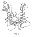
- Fig. 6 shows the situation immediately after that of Fig. 5, or immediately after that of Fig. 2.
- the common bale arm assembly 22 is returned to its raised position where a card 10 can be inserted by means of springs. It is also to be apprecieted that whereas in the description of the preferred embodiment the bale arm clamp 30 has been described as engaging the common bale arm assembly 22 only in the event of its being desired by the autoteller to retain tha card 10, the clamp solenoid 32 can be energised by the autoteller during a normal card reading as indicated in Fig. 2, in which instance the bale arm solenoid 28 would continue to be energised and the bale arm clamp 30 would lend added security to the holding of the card in the autoteller. Again it is to be appreciated that it is possible to read the card 10 with the bale arm clamp 30 in engagement with the common bale arm assembly 22 but with the bale arm solenoid 28 de-energised.
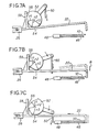
- Fig. 7A shows schematic detail of the cam assembly 24 operating the common bale arm assembly 22 immediately after the insertion of a card 10.
- the card 10 When the card 10 is inserted into the autoteller it lies upon a bed 46. With continued insertion the card engages a micro switch 48 which detects that the card is within .05 cm of the position it should occupy prior to reading. When the micro switch 48 is activated it informs the autoteller that a card 10 is present and requires to be read. The autoteller then activates the bale arm solenoid 28 which operates through a bale arm solenoid linkage 50 to turn the cam 52.
- the cam 52 being part of the cam assembly 24, comprises a portion of a first radius r1, a portion of a second radius r2, and a portion of a third radius r3.
- the cam 52 contacts the common bale arm assembly 22 at a first point 54 and has contact at a second point 56 with a projection 58 having a surface at 90° to the plane of the common bale arm assembly 22.
- the first radius r1 is smaller than the second radius r2 which in turn is smaller than the third radius r3.
- the cam 52 lies in a first position with a portion of the first radius r1 in contact with the projection 58 at the second point 56 and with a portion of the second radius r2 in contact with the bale arm assembly 22 at the first point 54.
- the bale arms 18, 22 are raised such that their tips are clear of the path of entry of the card 10 into the autoteller and onto the bed 46.
- the card 10 can be placed into and withdrawn from the autoteller when the bale arm assembly 22 is in this position.
- Fig. 7B shows the cam assembly 24 in an intermediate position during the activation of the bale arm solenoid 28.
- the cam 52 passes through an intermediate position where a portion thereof of the first radius r1 remains in contact with the projection 58 at the second point 56 but a new portion of radius r3 comes into contact with the bale arm assembly 22 in place of the portion previously in contact therewith having the second radius r2. Since the third radius r3 is greater than the second radius r2, the common bale arm assembly 22 moves from the first position, shown in phantom outline, being that occupied in Fig. 7A, to a second position where the plane of the common bale arm assembly, shown in solid line, is parallel to the plane of the card 10 as indicated by the arrow 8. Since the second point 56 has remained all this while in contact with a portion of the cam 52 of the first radius r1, the common bale arm assembly 22 has not moved at all in direction parallel to the direction of insertion of the card 10.
- Fig. 7C shows the mutual interaction of the cam assembly 24 and the common bale arm assembly 22 at the point where the bale arm solenoid 28 is completely energised.
- the cam 52 rests with a portion of the seoond radius r2 in contact with the projection 58 at the first point 56 and with a portion of the third radius r3 in contact with the bale arm assembly 22 at the first point 54. Since the first point 54 is in contact with and has remained in contact with a portion of the third radius r3, the bale arm assembly 22 stays in the plane of the card 10. The second point 56 of the projection 58 has ceased to be in contact with a point with the first radius r1 and has come into contact with a point of the second radius r2.
- the projection 58, and therefore the entire bale arm assembly 22 is forced backwards away from the slot 12 by a distance equal to the difference between the second radius r2 and the first radius r1. This has the effect of causing the tips of the bale arms. 18, 20 to engage the edge of the card 10 and, in the movement of the common bale arm assembly 22 away from the slot 12, to move the card 10 hard against the micro switch 48 bringing the card 10 into position for the card reader to read the card 10. In the backward movement of the common bale arm assembly 22 the pivot point thereof slides backwards in the sliding pivot 26.
- Fig. 8 shows a simplified isometric view of the apparatus for driving the card ejection pin 34.
- the pin driving wheel 36 is provided with an elastically coated face 60 having a semi-circular cross section channel 62 set therein.
- the elastically coated face 60 is provided on a steel core.
- the elastic material is preferably elastomeric polyurethane which was found to have the correct amount of friction against the card ejection pin 34.
- a pin idler wheel 64 made from steel, pushes hard against the pin driving wheel 36 and has a second semi-circular cross section groove 66 therein for holding .the card ejection pin in the first semi-circular cross section groove 62 in a mangle action.
- the pin driving wheel 36 is rotated by the electric motor 38 as previously described.
- the bed 46 whereon the card 10 is deposited when inserted through the slot 12 comprises a substantially semi-circular groove 68 set in the top thereof.
- the combination of the pin driving wheel 36 and of the pin idler wheel 64 causes the card ejection pin 34 to slide in the groove 68.
- the tip of the card ejection pin 34 projects a little way out of the groove 68 and, when the pin 34 is moved towards the card 10 the tip of the card ejection pin 34 projecting out of the groove 68, engages the edge of the card 10 and forces it across the bed 46.
- the bed 46 is continuous and solid, it is to be appreciated that the bed 46 can be provided with apertures and grooves where through magnetic heads can gain access to the rear of the card 10 for reading magnetic stripes recorded thereon.
- the bed 46 can be provided with apertures and grooves where through magnetic heads can gain access to the rear of the card 10 for reading magnetic stripes recorded thereon.
Landscapes
- Physics & Mathematics (AREA)
- General Physics & Mathematics (AREA)
- Engineering & Computer Science (AREA)
- Business, Economics & Management (AREA)
- Accounting & Taxation (AREA)
- Finance (AREA)
- Theoretical Computer Science (AREA)
- Mechanical Engineering (AREA)
- Control Of Vending Devices And Auxiliary Devices For Vending Devices (AREA)
- Control And Other Processes For Unpacking Of Materials (AREA)
Claims (10)
Priority Applications (5)
| Application Number | Priority Date | Filing Date | Title |
|---|---|---|---|
| GB08308689A GB2137393B (en) | 1983-03-29 | 1983-03-29 | Autoteller card-handling mechanism |
| US06/576,501 US4527052A (en) | 1983-03-29 | 1984-02-02 | Autoteller card handling mechanism |
| GB08405543A GB2137157A (en) | 1983-03-29 | 1984-03-02 | Bag Opening and Emptying Machine |
| EP84304216A EP0165349B1 (de) | 1983-03-29 | 1984-06-22 | Mechanismus zur Handhabung von Karten bei einem selbsttätigen Bankschalter |
| DE8484304216T DE3478159D1 (en) | 1984-06-22 | 1984-06-22 | Autoteller card-handling mechanism |
Applications Claiming Priority (3)
| Application Number | Priority Date | Filing Date | Title |
|---|---|---|---|
| GB08308689A GB2137393B (en) | 1983-03-29 | 1983-03-29 | Autoteller card-handling mechanism |
| GB838308681A GB8308681D0 (en) | 1983-03-29 | 1983-03-29 | Bag opening and emptying machine |
| EP84304216A EP0165349B1 (de) | 1983-03-29 | 1984-06-22 | Mechanismus zur Handhabung von Karten bei einem selbsttätigen Bankschalter |
Publications (2)
| Publication Number | Publication Date |
|---|---|
| EP0165349A1 EP0165349A1 (de) | 1985-12-27 |
| EP0165349B1 true EP0165349B1 (de) | 1989-05-10 |
Family
ID=27227174
Family Applications (1)
| Application Number | Title | Priority Date | Filing Date |
|---|---|---|---|
| EP84304216A Expired EP0165349B1 (de) | 1983-03-29 | 1984-06-22 | Mechanismus zur Handhabung von Karten bei einem selbsttätigen Bankschalter |
Country Status (3)
| Country | Link |
|---|---|
| US (1) | US4527052A (de) |
| EP (1) | EP0165349B1 (de) |
| GB (2) | GB2137393B (de) |
Families Citing this family (29)
| Publication number | Priority date | Publication date | Assignee | Title |
|---|---|---|---|---|
| US4724310A (en) * | 1984-07-02 | 1988-02-09 | Tokyo Tatsuno Co., Ltd. | Device for inserting and holding an IC card as an external memory during reading and writing operations |
| US4784289A (en) * | 1985-11-13 | 1988-11-15 | Tokyo Electric Co., Ltd. | Ticket issuing device for a ticket machine |
| WO1990000500A2 (en) * | 1988-07-07 | 1990-01-25 | John Earp | Packaged food recovery apparatus |
| US5146069A (en) * | 1988-09-19 | 1992-09-08 | Fuji Photo Film Co., Ltd. | Device for loading and unloading a memory cartridge using a sliding member |
| ATE182999T1 (de) * | 1988-10-14 | 1999-08-15 | Omron Tateisi Electronics Co | Kartenlesegerät mit verriegelung |
| DE3914459A1 (de) * | 1989-05-02 | 1990-11-08 | Steinecker Maschf Anton | Vorrichtung zum entleeren von mit schuettgut gefuellten saecken |
| US5089694A (en) * | 1990-03-07 | 1992-02-18 | General Signal Corporation | Card reader device having automatic means for clamping the card to be read and for automatically ejecting the card at the end of the card reading and writing operations |
| EP0460606B1 (de) * | 1990-06-07 | 1996-10-02 | Kabushiki Kaisha Toshiba | Lese-/Schreibvorrichtung für eine Karte |
| JPH087480Y2 (ja) * | 1990-06-21 | 1996-03-04 | 株式会社三協精機製作所 | カードリーダーのカード搬送機構 |
| DE4022276C1 (en) * | 1990-07-12 | 1991-12-19 | Sic Ag, Basel, Ch | Automatic bag opening appts. - has housing with scissor-type blades at bottom, pivoting on axle |
| US5180905A (en) * | 1990-11-23 | 1993-01-19 | Verifone Inc. | Card reader apparatus with replaceable card guide |
| US5440108A (en) * | 1991-10-11 | 1995-08-08 | Verifone, Inc. | System and method for dispensing and revalung cash cards |
| US5434404A (en) * | 1991-10-11 | 1995-07-18 | Verifone, Inc. | Linear scanner apparatus for communicating with a data card |
| WO1993007594A1 (en) * | 1991-10-11 | 1993-04-15 | Verifone, Inc. | Dispensing machine with data card scanner apparatus and enhanced features |
| BE1005592A4 (fr) * | 1992-02-05 | 1993-11-16 | Schepens Henri | Dispositif semi-automatique d'ouverture et de vidage de sacs. |
| JPH05303821A (ja) * | 1992-04-24 | 1993-11-16 | Olympus Optical Co Ltd | カード状記録媒体の記録再生装置 |
| US5277014A (en) * | 1992-09-14 | 1994-01-11 | Abr Corporation | Bag discharge station |
| DE4235695C1 (de) * | 1992-10-22 | 1994-04-21 | Copyguard Electronic Gmbh | Vorrichtung zum Halten von Chipkarten |
| DE9321528U1 (de) * | 1993-06-04 | 1999-04-08 | Vendoret Holding S.A., Luxemburg/Luxembourg | Karte für ein Pfandschloß |
| DE4407684C1 (de) * | 1994-03-08 | 1995-06-29 | Henkel Ecolab Gmbh & Co Ohg | Vorrichtung zum Öffnen und dosierten Entleeren von Säcken |
| US5780827A (en) * | 1996-10-16 | 1998-07-14 | Verifone, Inc. | Landing contact mechanism and card latch for smart card reader/writer |
| GB2351587A (en) * | 1999-06-29 | 2001-01-03 | Ncr Int Inc | Fraud protection for a self-service terminal |
| EP1231559B1 (de) * | 2001-02-09 | 2003-11-26 | ddm hopt + schuler GmbH & Co. KG | Kartenleser |
| CN103625710B (zh) * | 2013-12-11 | 2015-08-26 | 天津市艾盟科技发展有限公司 | 自动破袋投料机 |
| GB2537407A (en) * | 2015-04-16 | 2016-10-19 | Palamatic Ltd | Apparatus and method for opening a sealed sack containing particulate material |
| CN108910197B (zh) * | 2017-01-13 | 2021-01-12 | 中国计量大学 | 振动除残料式自动拆包卸料方法 |
| EP3704027B1 (de) * | 2017-11-03 | 2021-08-04 | Main Tech S.r.l. | Vorrichtung zum entladen von material und beutelentleerungsvorrichtung mit besagter vorrichtung |
| FR3110566B1 (fr) * | 2020-05-20 | 2022-09-23 | Ouest Elevage | Dispositif et procede d’ouverture et de vidage automatique d’un contenant de produit poudreux |
| CN113830445B (zh) * | 2021-08-20 | 2023-01-13 | 广东邦普循环科技有限公司 | 固定组件及固定装置 |
Family Cites Families (13)
| Publication number | Priority date | Publication date | Assignee | Title |
|---|---|---|---|---|
| DE1449645B2 (de) * | 1963-09-12 | 1971-07-08 | Siemens AG. 1000 Berlin u 8000 München | Ausrichteinrichtung fuer lochkarten |
| NL6814743A (de) * | 1968-10-15 | 1970-04-17 | ||
| US3939327A (en) * | 1969-08-05 | 1976-02-17 | Data Source Corporation | Optical reading apparatus and method |
| US3850426A (en) * | 1970-06-22 | 1974-11-26 | Amp Inc | A card reader having automatic card positioning means |
| US3850299A (en) * | 1973-12-03 | 1974-11-26 | Ncr Co | Card transport and capture mechanism |
| JPS5323793A (en) * | 1976-08-12 | 1978-03-04 | Narasaki Shipbuilding Co Ltd | Device for automatically opening sack |
| US4087680A (en) * | 1977-04-22 | 1978-05-02 | Burroughs Corporation | Semiautomatic credit card information handling apparatus |
| US4151564A (en) * | 1977-12-02 | 1979-04-24 | Burroughs Corporation | Modular, semiautomatic credit card reader/writer apparatus |
| GB2040254B (en) * | 1979-01-17 | 1982-12-15 | Sim Bianca Srl | Machine for emptying sacks |
| FR2450768A1 (fr) * | 1979-03-05 | 1980-10-03 | Satil Sa | Procede et dispositif pour vider mecaniquement des sacs |
| DK146581A (da) * | 1981-03-31 | 1982-10-01 | Wittenborgs Automatfab | Betalingsanlaeg med magnetkort |
| GB2099390A (en) * | 1981-06-02 | 1982-12-08 | Simon Solitec Ltd | A bag opening and emptying machine |
| DE3140467A1 (de) * | 1981-10-12 | 1983-04-21 | Luco-Technic Gmbh Verfahrenstechnische Anlagen, 6474 Ortenberg | "handbetaetigte sackleervorrichtung" |
-
1983
- 1983-03-29 GB GB08308689A patent/GB2137393B/en not_active Expired
-
1984
- 1984-02-02 US US06/576,501 patent/US4527052A/en not_active Expired - Lifetime
- 1984-03-02 GB GB08405543A patent/GB2137157A/en not_active Withdrawn
- 1984-06-22 EP EP84304216A patent/EP0165349B1/de not_active Expired
Also Published As
| Publication number | Publication date |
|---|---|
| GB8405543D0 (en) | 1984-04-04 |
| US4527052A (en) | 1985-07-02 |
| GB2137393B (en) | 1986-02-05 |
| GB2137157A (en) | 1984-10-03 |
| GB8308689D0 (en) | 1983-05-05 |
| EP0165349A1 (de) | 1985-12-27 |
| GB2137393A (en) | 1984-10-03 |
Similar Documents
| Publication | Publication Date | Title |
|---|---|---|
| US4527052A (en) | Autoteller card handling mechanism | |
| US5331138A (en) | Hybrid card reader | |
| EP0696009B1 (de) | Kartenlesegerät mit Verriegelung | |
| US5912446A (en) | Card reader with carriage powered by movement of inserted card | |
| US6761310B2 (en) | Card reader | |
| CA1057255A (en) | Card retrieval means | |
| US6729538B2 (en) | Card reader module | |
| JP4210217B2 (ja) | Icカードリーダ | |
| US20010052546A1 (en) | Card processing method | |
| JP4293317B2 (ja) | Iccカード・リーダ/ライタ | |
| EP0996936B1 (de) | Zusatzvorrichtung zum Bearbeiten eines Sparbuchs und Verfahren zum Betreiben der Vorrichtung | |
| JPH0468671B2 (de) | ||
| US4692602A (en) | Apparatus for sensing and/or writing information on cards, passports and checks and the like | |
| US5589681A (en) | Card receiver enabling a broken card to be ejected and card reader using it | |
| US4136819A (en) | Card processing apparatus | |
| JPH02213990A (ja) | Icカードリーダ・ライタ | |
| JPS6124199B2 (de) | ||
| JPS6142313B2 (de) | ||
| EP0809208A2 (de) | Verfahren und Vorrichtung zum Bedrucken eines Trägers und zum Erfassen und Lesen der auf dem Träger gedruckten Informationen | |
| JPH0335379A (ja) | Icカードリーダ | |
| JPS62175962A (ja) | カ−ドリ−ダ | |
| JPH03189785A (ja) | カードリーダ | |
| JP2915755B2 (ja) | 磁気カードリーダ | |
| JPS6227968Y2 (de) | ||
| JPH0521166Y2 (de) |
Legal Events
| Date | Code | Title | Description |
|---|---|---|---|
| PUAI | Public reference made under article 153(3) epc to a published international application that has entered the european phase |
Free format text: ORIGINAL CODE: 0009012 |
|
| 17P | Request for examination filed |
Effective date: 19840628 |
|
| AK | Designated contracting states |
Designated state(s): BE DE FR IT NL SE |
|
| RAP1 | Party data changed (applicant data changed or rights of an application transferred) |
Owner name: UNISYS CORPORATION |
|
| 17Q | First examination report despatched |
Effective date: 19871119 |
|
| GRAA | (expected) grant |
Free format text: ORIGINAL CODE: 0009210 |
|
| AK | Designated contracting states |
Kind code of ref document: B1 Designated state(s): BE DE FR IT NL SE |
|
| REF | Corresponds to: |
Ref document number: 3478159 Country of ref document: DE Date of ref document: 19890615 |
|
| ET | Fr: translation filed | ||
| ITF | It: translation for a ep patent filed | ||
| PLBE | No opposition filed within time limit |
Free format text: ORIGINAL CODE: 0009261 |
|
| STAA | Information on the status of an ep patent application or granted ep patent |
Free format text: STATUS: NO OPPOSITION FILED WITHIN TIME LIMIT |
|
| 26N | No opposition filed | ||
| PGFP | Annual fee paid to national office [announced via postgrant information from national office to epo] |
Ref country code: SE Payment date: 19920521 Year of fee payment: 9 |
|
| PGFP | Annual fee paid to national office [announced via postgrant information from national office to epo] |
Ref country code: NL Payment date: 19920630 Year of fee payment: 9 |
|
| PGFP | Annual fee paid to national office [announced via postgrant information from national office to epo] |
Ref country code: BE Payment date: 19920708 Year of fee payment: 9 |
|
| PG25 | Lapsed in a contracting state [announced via postgrant information from national office to epo] |
Ref country code: SE Effective date: 19930623 |
|
| ITTA | It: last paid annual fee | ||
| PG25 | Lapsed in a contracting state [announced via postgrant information from national office to epo] |
Ref country code: BE Effective date: 19930630 |
|
| BERE | Be: lapsed |
Owner name: UNISYS CORP. Effective date: 19930630 |
|
| PG25 | Lapsed in a contracting state [announced via postgrant information from national office to epo] |
Ref country code: NL Effective date: 19940101 |
|
| NLV4 | Nl: lapsed or anulled due to non-payment of the annual fee | ||
| PGFP | Annual fee paid to national office [announced via postgrant information from national office to epo] |
Ref country code: FR Payment date: 19940613 Year of fee payment: 11 |
|
| PGFP | Annual fee paid to national office [announced via postgrant information from national office to epo] |
Ref country code: DE Payment date: 19940630 Year of fee payment: 11 |
|
| EUG | Se: european patent has lapsed |
Ref document number: 84304216.9 Effective date: 19940110 |
|
| PG25 | Lapsed in a contracting state [announced via postgrant information from national office to epo] |
Ref country code: FR Effective date: 19960229 |
|
| PG25 | Lapsed in a contracting state [announced via postgrant information from national office to epo] |
Ref country code: DE Effective date: 19960301 |
|
| REG | Reference to a national code |
Ref country code: FR Ref legal event code: ST |