EP0165468B1 - Dispositif pour ajuster la densité réciproque d'air d'admission du moteur - Google Patents
Dispositif pour ajuster la densité réciproque d'air d'admission du moteur Download PDFInfo
- Publication number
- EP0165468B1 EP0165468B1 EP85105984A EP85105984A EP0165468B1 EP 0165468 B1 EP0165468 B1 EP 0165468B1 EP 85105984 A EP85105984 A EP 85105984A EP 85105984 A EP85105984 A EP 85105984A EP 0165468 B1 EP0165468 B1 EP 0165468B1
- Authority
- EP
- European Patent Office
- Prior art keywords
- engine
- adjusting
- intake air
- heating element
- air
- Prior art date
- Legal status (The legal status is an assumption and is not a legal conclusion. Google has not performed a legal analysis and makes no representation as to the accuracy of the status listed.)
- Expired - Lifetime
Links
- 238000010438 heat treatment Methods 0.000 claims description 22
- OKTJSMMVPCPJKN-UHFFFAOYSA-N Carbon Chemical compound [C] OKTJSMMVPCPJKN-UHFFFAOYSA-N 0.000 claims description 16
- 229910052799 carbon Inorganic materials 0.000 claims description 16
- 239000011345 viscous material Substances 0.000 claims description 14
- 239000000446 fuel Substances 0.000 description 16
- 238000002347 injection Methods 0.000 description 8
- 239000007924 injection Substances 0.000 description 8
- 239000000203 mixture Substances 0.000 description 6
- 230000002950 deficient Effects 0.000 description 3
- 230000000694 effects Effects 0.000 description 2
- 239000000126 substance Substances 0.000 description 2
- 238000002485 combustion reaction Methods 0.000 description 1
- 230000003247 decreasing effect Effects 0.000 description 1
- 230000001419 dependent effect Effects 0.000 description 1
- 238000011144 upstream manufacturing Methods 0.000 description 1
- 238000010792 warming Methods 0.000 description 1
Images

Classifications
-
- F—MECHANICAL ENGINEERING; LIGHTING; HEATING; WEAPONS; BLASTING
- F02—COMBUSTION ENGINES; HOT-GAS OR COMBUSTION-PRODUCT ENGINE PLANTS
- F02D—CONTROLLING COMBUSTION ENGINES
- F02D31/00—Use of speed-sensing governors to control combustion engines, not otherwise provided for
- F02D31/001—Electric control of rotation speed
- F02D31/002—Electric control of rotation speed controlling air supply
- F02D31/003—Electric control of rotation speed controlling air supply for idle speed control
- F02D31/005—Electric control of rotation speed controlling air supply for idle speed control by controlling a throttle by-pass
-
- F—MECHANICAL ENGINEERING; LIGHTING; HEATING; WEAPONS; BLASTING
- F02—COMBUSTION ENGINES; HOT-GAS OR COMBUSTION-PRODUCT ENGINE PLANTS
- F02M—SUPPLYING COMBUSTION ENGINES IN GENERAL WITH COMBUSTIBLE MIXTURES OR CONSTITUENTS THEREOF
- F02M3/00—Idling devices for carburettors
- F02M3/06—Increasing idling speed
-
- F—MECHANICAL ENGINEERING; LIGHTING; HEATING; WEAPONS; BLASTING
- F02—COMBUSTION ENGINES; HOT-GAS OR COMBUSTION-PRODUCT ENGINE PLANTS
- F02M—SUPPLYING COMBUSTION ENGINES IN GENERAL WITH COMBUSTIBLE MIXTURES OR CONSTITUENTS THEREOF
- F02M31/00—Apparatus for thermally treating combustion-air, fuel, or fuel-air mixture
- F02M31/02—Apparatus for thermally treating combustion-air, fuel, or fuel-air mixture for heating
- F02M31/12—Apparatus for thermally treating combustion-air, fuel, or fuel-air mixture for heating electrically
- F02M31/13—Combustion air
-
- Y—GENERAL TAGGING OF NEW TECHNOLOGICAL DEVELOPMENTS; GENERAL TAGGING OF CROSS-SECTIONAL TECHNOLOGIES SPANNING OVER SEVERAL SECTIONS OF THE IPC; TECHNICAL SUBJECTS COVERED BY FORMER USPC CROSS-REFERENCE ART COLLECTIONS [XRACs] AND DIGESTS
- Y02—TECHNOLOGIES OR APPLICATIONS FOR MITIGATION OR ADAPTATION AGAINST CLIMATE CHANGE
- Y02T—CLIMATE CHANGE MITIGATION TECHNOLOGIES RELATED TO TRANSPORTATION
- Y02T10/00—Road transport of goods or passengers
- Y02T10/10—Internal combustion engine [ICE] based vehicles
- Y02T10/12—Improving ICE efficiencies
Definitions
- the present invention relates to an apparatus for adjusting the specific volume of intake air for an engine of the kind referred to in the precharacterizing portion of patent claims 1, 2 and 6, respectively.
- Such an apparatus is known for example from DE-A-25 36 432.
- an air-fuel mixture is formed by a carburetor by making use of a vacuum produced during the intake stroke, and the amount of the air-fuel mixture to be supplied is controlled by varying the degree of opening of a throttle valve.
- the other type of automotive engine has been designed such that a fuel injection valve is disposed in an intake passage, and the specific volume of intake air is controlled by varying the degree of opening of a throttle valve, while the fuel injection amount is controlled by varying the period of time during which the fuel injection valve is open, whereby the amount of the air-fuel mixture as a whole is controlled.
- the throttle valve is opened and closed in operatively associated relation with the accelerator pedal, and the fuel within the carburetor and the air passing through an air cleaner are mixed together and pass through the area around the throttle valve. Consequently, the throttle valve and the intake passage wall surface portion surrounding the valve are wet at all times. For this reason, even if back-fire gas or blowby gas flows backward as far as the vicinity of the throttle valve and the carbon and viscous substances contained in the gas to the valve and its surrounding area, they are washed away by the air-fuel mixture, whereby the throttle valve and the intake passage wall surface portion are kept relatively clean.
- an apparatus for adjusting a specific volume of intake air for an engine of the type having a by-pass passage which by-passes a throttle valve for adjusting the specific volume of intake air flowing through an intake passage, and an orifice defined by an adjusting valve body and a valve seat and adapted to adjust the specific volume of intake air passing through said by-pass passage, further comprising a heating element provided on a downstream side of said orifice in said by-pass passage, said heating element allowing said intake air to pass therethrough.
- the heating device only functions to heat the mixture of air from the main body portion and supplied through a branch intake duct and fuel from a fuel injector.
- an air valve main body 1 is formed with an intake passage in which is installed a throttle valve 3 supported by a shaft 2.
- a fuel injection valve (not shown) is installed on the downstream side of the throttle valve 3.
- the air valve main body 1 is further formed with an idling air passage (by-pass passage) 4 which by-passes the throttle valve 3.
- An adjusting valve body 6 and a valve seat 7 for adjusting the orifice area are installed in the vicinity of an outlet-side passage 5 of the by-pass passage 4.
- the throttle valve 3 is in a nearly full closed position. Consequently, the air intaken during idling is supplied into the combustion chamber of the engine through the by-pass passage 4.
- the carbon and viscous substances contained in back-fire gas, blowby gas or EGR gas may gather on the downstream side of the throttle valve 3 and finally adhere to the respective distal end portions of the valve seat 7 and the adjusting valve body 6 installed in the by- pass passage 4.
- the embodiment of the present invention shown in Fig. 1 employs a lattice-shaped heating element 8 which has a relatively small resistance to passage of air and is disposed on the downstream side of the adjusting valve body 6 and the valve seat 7 in the by-pass passage 4, whereby carbon and viscous substances which may undesirably flow back into the by-pass passage 4 are caused to adhere to the lattice of the heating element 8 before contacting the valve seat 7 or the adjusting valve body 6.
- the heating element 8 is connected with a vehicle speed switch 10 which is connected in series to an ignition switch 9.
- the vehicle speed switch 10 is adapted to energize the heating element 8 when the vehicle speed exceeds a predetermined value.
- the switch 10 turns on, the heating element 8 is caused to heat up and burn the carbon and other substances adhering to the lattice.
- the reason why the heating element 8 is energized when the vehicle speed switch 10 is closed as the vehicle speed exceeds a predetermined value is explained by the following. If the heating element 8 is supplied with electric current during an idling operation, since at this time no voltage is applied to the battery by the generator, the battery voltage drops, so that it cannot apply a sufficiently high voltage to the spark plug. As a result, the engine speed becomes unstable. In the worst case, the engine may stall.
- the heating element 8 is preferably provided as close to the engine as possible, because carbon and viscous substances more easily adhere to the heating element 8 if it is closer to the engine. Further, the smaller the gap between individual lattice bars constituting the heating element 8, the more easily carbon and other substances adhere to the heating element 8. It is, however, necessary for the entire air passage area of the heating element 8 to be larger than the area of the orifice defined by the valve seat 7 and the adjusting valve body 6.
- carbon and viscous substances which may flow back into the by-pass passage 4 are caused to adhere to the lattice-shaped heating element 8 before contacting the valve seat 7 or the adjusting valve body 6 and are burnt by the heat generated by the heating element 8. It is therefore possible to prevent any adhesion of carbon and viscous substances to the adjusting valve body 6 or the valve seat 7 in the by-pass passage 4. Accordingly, it is possible to prevent the specific volume of intake air from becoming deficient during a low-speed engine running in which the amount of the air passing through the by-pass passage 4 is small.
- Fig. 2 is a sectional view of an essential part of the arrangement shown in Fig. 1, which shows another embodiment of the present invention.
- the heating element 8 is mounted on the air valve main body 1, together with the valve seat 7, in the embodiment shown in Fig. 2 the valve seat 7 is formed with a sharp-edged shape and the lattice-shaped heating element 8 is housed inside the valve seat 7.
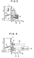
- the present invention has been described above through its embodiments in an apparatus for adjusting the specific volume of intake air for a fuel injection type engine in which the fuel injection valve is disposed on the downstream side of the throttle valve 3, it may also be applied to another type of engine in which a fuel injection valve 11 is disposed on the upstream side of the throttle valve 3 in the manner shown in Fig. 3, and it is still possible to obtain an advantageous effect similar to the above.
- the invention may be applied to still another type of engine which is provided with an air regulator 14 which controls the idling speed of the engine during warming up or an air amount control valve 14 which operates during deceleration and when the cooler is switched on, the air regulator or the air amount control valve 14 being connected to the inlet side of the by-pass passage 4 through an air inlet pipe 12 and connected to the outlet-side passage 5 through an air outlet pipe 13.
- an air regulator 14 which controls the idling speed of the engine during warming up
- an air amount control valve 14 which operates during deceleration and when the cooler is switched on
- the air regulator or the air amount control valve 14 being connected to the inlet side of the by-pass passage 4 through an air inlet pipe 12 and connected to the outlet-side passage 5 through an air outlet pipe 13.
- the present invention advantageously makes it possible to prevent any adhesion of carbon and viscous substances to the adjusting valve body or the valve seat in the by- pass passage and consequently to prevent the specific volume of intake air from becoming deficient during low-speed engine running in which the amount of the air passing through the by-pass passage is small.
Landscapes
- Engineering & Computer Science (AREA)
- Chemical & Material Sciences (AREA)
- Combustion & Propulsion (AREA)
- Mechanical Engineering (AREA)
- General Engineering & Computer Science (AREA)
- Control Of Throttle Valves Provided In The Intake System Or In The Exhaust System (AREA)
- Electrical Control Of Air Or Fuel Supplied To Internal-Combustion Engine (AREA)
Claims (6)
Applications Claiming Priority (2)
| Application Number | Priority Date | Filing Date | Title |
|---|---|---|---|
| JP59100767A JPS60243330A (ja) | 1984-05-18 | 1984-05-18 | エンジンの吸入空気量調整装置 |
| JP100767/84 | 1984-05-18 |
Publications (3)
| Publication Number | Publication Date |
|---|---|
| EP0165468A2 EP0165468A2 (fr) | 1985-12-27 |
| EP0165468A3 EP0165468A3 (en) | 1987-04-08 |
| EP0165468B1 true EP0165468B1 (fr) | 1990-02-07 |
Family
ID=14282645
Family Applications (1)
| Application Number | Title | Priority Date | Filing Date |
|---|---|---|---|
| EP85105984A Expired - Lifetime EP0165468B1 (fr) | 1984-05-18 | 1985-05-15 | Dispositif pour ajuster la densité réciproque d'air d'admission du moteur |
Country Status (6)
| Country | Link |
|---|---|
| US (1) | US4712531A (fr) |
| EP (1) | EP0165468B1 (fr) |
| JP (1) | JPS60243330A (fr) |
| KR (1) | KR850008703A (fr) |
| CA (1) | CA1253410A (fr) |
| DE (1) | DE3575977D1 (fr) |
Families Citing this family (12)
| Publication number | Priority date | Publication date | Assignee | Title |
|---|---|---|---|---|
| KR910001056Y1 (ko) * | 1987-02-26 | 1991-02-21 | 미쯔비시 덴끼 가부시끼가이샤 | 기관의 흡기량 제어장치 |
| KR100353078B1 (ko) * | 1999-12-08 | 2002-09-19 | 현대자동차주식회사 | 자동차용 흡기계통의 카본 흡착 방지장치 |
| JP2003262159A (ja) * | 2002-03-08 | 2003-09-19 | Walbro Japan Inc | 気化器のアイドル燃料供給装置 |
| US8199919B2 (en) | 2006-06-01 | 2012-06-12 | Personics Holdings Inc. | Earhealth monitoring system and method II |
| US8194864B2 (en) | 2006-06-01 | 2012-06-05 | Personics Holdings Inc. | Earhealth monitoring system and method I |
| US8208644B2 (en) | 2006-06-01 | 2012-06-26 | Personics Holdings Inc. | Earhealth monitoring system and method III |
| WO2007143580A2 (fr) | 2006-06-01 | 2007-12-13 | Personics Holdings Inc. | Système de surveillance de niveau de pression sonore a l'entrée de l'oreille |
| WO2007147077A2 (fr) | 2006-06-14 | 2007-12-21 | Personics Holdings Inc. | Système de régulation de protection d'oreille |
| WO2008153589A2 (fr) | 2007-06-01 | 2008-12-18 | Personics Holdings Inc. | Système et procédé iv de surveillance de l'état de santé d'une oreille |
| JP6933591B2 (ja) * | 2018-02-23 | 2021-09-08 | 株式会社ミクニ | スロットル装置及び燃料蒸発ガス回収システム |
| CN111102110A (zh) * | 2019-12-30 | 2020-05-05 | 潍柴动力股份有限公司 | 柴油机进气结构及柴油车 |
| CN113431678B (zh) * | 2021-05-27 | 2023-03-21 | 株式会社三国 | 一种节气门体防积碳结构 |
Family Cites Families (14)
| Publication number | Priority date | Publication date | Assignee | Title |
|---|---|---|---|---|
| DE354909C (de) * | 1920-01-24 | 1922-06-16 | Fried Krupp Akt Ges Germaniawe | Einrichtung zum Vorwaermen des Brennstoffes von Verbrennungskraftmaschinen |
| US1525824A (en) * | 1922-08-04 | 1925-02-10 | Gen Electric | Method of and apparatus for heating fuel mixtures |
| US2115634A (en) * | 1933-05-20 | 1938-04-26 | Otto Gutmann | Heavy oil carburetor |
| US2155670A (en) * | 1937-01-18 | 1939-04-25 | Albert C Macbeth | Control for carburetor idling systems |
| US2139777A (en) * | 1937-12-09 | 1938-12-13 | Skok Alois | Electric and automatic fuel vaporizer |
| US3787037A (en) * | 1971-06-07 | 1974-01-22 | M Motooka | Carburation system |
| US3996315A (en) * | 1973-11-09 | 1976-12-07 | Rene Laurent Herail | Vaporization apparatus for internal combustion engines |
| DE2536432A1 (de) * | 1975-08-16 | 1977-02-24 | Volkswagenwerk Ag | Kaltstart- und warmlaufeinrichtung |
| FR2333969A1 (fr) * | 1975-12-03 | 1977-07-01 | Renault | Diffuseur a col sonique pour carburateurs |
| US4177778A (en) * | 1976-07-29 | 1979-12-11 | Nippondenso Co., Ltd. | Carburetors with heating device |
| JPS5453714A (en) * | 1977-10-06 | 1979-04-27 | Toyota Motor Corp | Internal combustion engine fuel injector |
| US4308845A (en) * | 1979-10-22 | 1982-01-05 | Chrysler Corporation | Early fuel evaporation with bypass |
| US4387690A (en) * | 1981-11-12 | 1983-06-14 | Texas Instruments Incorporated | Fuel evaporation device |
| JPS58165547A (ja) * | 1982-03-26 | 1983-09-30 | Nissan Motor Co Ltd | デイ−ゼルエンジンの振動低減装置 |
-
1984
- 1984-05-18 JP JP59100767A patent/JPS60243330A/ja active Pending
-
1985
- 1985-05-02 KR KR1019850002977A patent/KR850008703A/ko not_active Ceased
- 1985-05-07 CA CA000480919A patent/CA1253410A/fr not_active Expired
- 1985-05-08 US US06/731,734 patent/US4712531A/en not_active Expired - Fee Related
- 1985-05-15 DE DE8585105984T patent/DE3575977D1/de not_active Expired - Lifetime
- 1985-05-15 EP EP85105984A patent/EP0165468B1/fr not_active Expired - Lifetime
Also Published As
| Publication number | Publication date |
|---|---|
| DE3575977D1 (de) | 1990-03-15 |
| EP0165468A2 (fr) | 1985-12-27 |
| JPS60243330A (ja) | 1985-12-03 |
| CA1253410A (fr) | 1989-05-02 |
| EP0165468A3 (en) | 1987-04-08 |
| KR850008703A (ko) | 1985-12-21 |
| US4712531A (en) | 1987-12-15 |
Similar Documents
| Publication | Publication Date | Title |
|---|---|---|
| US4712531A (en) | Apparatus for adjusting specific volume of intake air for engine | |
| US4538412A (en) | Exhaust gas cleaning device for diesel engines | |
| JPH06207509A (ja) | 内燃機関の排ガスを浄化するためのバーナシステム | |
| EP0892166A3 (fr) | Système de contrôle d'injection de carburant pour moteur diesel | |
| CA2138563C (fr) | Dispositif de determination de la deterioration du catalyseur d'un moteur a combustion interne | |
| JPH08270509A (ja) | ヂーゼルエンジン組立体 | |
| US4426968A (en) | Carburetor with means for compensation of idling revolution | |
| KR940008274B1 (ko) | 내연기관의 아이들 제어밸브의 제어방법 및 장치 | |
| CA1127742A (fr) | Regulateur de melange air/carburant | |
| DE3011523C2 (de) | Luft-Brennstoff-Verhältnisregelanordnung für einen Verbrennungsmotor | |
| US4700676A (en) | Intake control device | |
| US4510902A (en) | Fuel supply control in deceleration of an internal combustion engine for vehicles | |
| US4336779A (en) | Carburation devices | |
| US5337715A (en) | Engine deceleration intake air flow reduction and fuel shut-off control | |
| US4234522A (en) | Variable diffuser for carburetors | |
| JPS6045751B2 (ja) | 燃料噴射式火花点火機関の吸気装置 | |
| US4182297A (en) | Heat control system for a two-cycle engine | |
| US4354472A (en) | Fuel injection system | |
| AU5869186A (en) | Internal combustion engine pollutant control system | |
| JPS628358Y2 (fr) | ||
| JPS60111032A (ja) | エンジンの吸入空気量制御装置 | |
| US4342288A (en) | Water induction system for internal combustion engines | |
| JPH1073054A (ja) | 内燃機関の燃料制限装置 | |
| CA1177343A (fr) | Systeme de carburation pour moteur a combustion interne | |
| JPH0253625B2 (fr) |
Legal Events
| Date | Code | Title | Description |
|---|---|---|---|
| PUAI | Public reference made under article 153(3) epc to a published international application that has entered the european phase |
Free format text: ORIGINAL CODE: 0009012 |
|
| AK | Designated contracting states |
Designated state(s): CH DE FR GB IT LI NL SE |
|
| PUAL | Search report despatched |
Free format text: ORIGINAL CODE: 0009013 |
|
| AK | Designated contracting states |
Kind code of ref document: A3 Designated state(s): CH DE FR GB IT LI NL SE |
|
| 17P | Request for examination filed |
Effective date: 19870422 |
|
| 17Q | First examination report despatched |
Effective date: 19871208 |
|
| GRAA | (expected) grant |
Free format text: ORIGINAL CODE: 0009210 |
|
| RBV | Designated contracting states (corrected) |
Designated state(s): DE FR GB SE |
|
| AK | Designated contracting states |
Kind code of ref document: B1 Designated state(s): DE FR GB SE |
|
| REF | Corresponds to: |
Ref document number: 3575977 Country of ref document: DE Date of ref document: 19900315 |
|
| ET | Fr: translation filed | ||
| PLBE | No opposition filed within time limit |
Free format text: ORIGINAL CODE: 0009261 |
|
| STAA | Information on the status of an ep patent application or granted ep patent |
Free format text: STATUS: NO OPPOSITION FILED WITHIN TIME LIMIT |
|
| 26N | No opposition filed | ||
| PGFP | Annual fee paid to national office [announced via postgrant information from national office to epo] |
Ref country code: SE Payment date: 19910405 Year of fee payment: 7 |
|
| PGFP | Annual fee paid to national office [announced via postgrant information from national office to epo] |
Ref country code: FR Payment date: 19920331 Year of fee payment: 8 |
|
| PG25 | Lapsed in a contracting state [announced via postgrant information from national office to epo] |
Ref country code: SE Effective date: 19920516 |
|
| PGFP | Annual fee paid to national office [announced via postgrant information from national office to epo] |
Ref country code: GB Payment date: 19930505 Year of fee payment: 9 |
|
| PG25 | Lapsed in a contracting state [announced via postgrant information from national office to epo] |
Ref country code: FR Effective date: 19940131 |
|
| REG | Reference to a national code |
Ref country code: FR Ref legal event code: ST |
|
| PG25 | Lapsed in a contracting state [announced via postgrant information from national office to epo] |
Ref country code: GB Effective date: 19940515 |
|
| PGFP | Annual fee paid to national office [announced via postgrant information from national office to epo] |
Ref country code: DE Payment date: 19940729 Year of fee payment: 10 |
|
| GBPC | Gb: european patent ceased through non-payment of renewal fee |
Effective date: 19940515 |
|
| EUG | Se: european patent has lapsed |
Ref document number: 85105984.0 Effective date: 19921204 |
|
| PG25 | Lapsed in a contracting state [announced via postgrant information from national office to epo] |
Ref country code: DE Effective date: 19960201 |