EP0165477A2 - Revêtement pour cylindre ou tambour transportant des feuilles dans les machines rotatives d'impression offsetet utilisation d'un tel revêtement. - Google Patents
Revêtement pour cylindre ou tambour transportant des feuilles dans les machines rotatives d'impression offsetet utilisation d'un tel revêtement. Download PDFInfo
- Publication number
- EP0165477A2 EP0165477A2 EP85106073A EP85106073A EP0165477A2 EP 0165477 A2 EP0165477 A2 EP 0165477A2 EP 85106073 A EP85106073 A EP 85106073A EP 85106073 A EP85106073 A EP 85106073A EP 0165477 A2 EP0165477 A2 EP 0165477A2
- Authority
- EP
- European Patent Office
- Prior art keywords
- elevator
- sheet
- elevator according
- openings
- printing
- Prior art date
- Legal status (The legal status is an assumption and is not a legal conclusion. Google has not performed a legal analysis and makes no representation as to the accuracy of the status listed.)
- Granted
Links
- 238000007645 offset printing Methods 0.000 title abstract description 4
- 238000007639 printing Methods 0.000 claims abstract description 57
- 238000003860 storage Methods 0.000 claims abstract description 9
- 238000007664 blowing Methods 0.000 claims abstract description 6
- 239000000463 material Substances 0.000 claims abstract description 4
- 239000011324 bead Substances 0.000 claims description 27
- 239000011521 glass Substances 0.000 claims description 27
- 239000004744 fabric Substances 0.000 claims description 12
- 239000011888 foil Substances 0.000 claims description 2
- 229910052751 metal Inorganic materials 0.000 claims description 2
- 239000002184 metal Substances 0.000 claims description 2
- 239000004033 plastic Substances 0.000 claims description 2
- PXHVJJICTQNCMI-UHFFFAOYSA-N Nickel Chemical compound [Ni] PXHVJJICTQNCMI-UHFFFAOYSA-N 0.000 description 19
- VYZAMTAEIAYCRO-UHFFFAOYSA-N Chromium Chemical compound [Cr] VYZAMTAEIAYCRO-UHFFFAOYSA-N 0.000 description 10
- 229910052759 nickel Inorganic materials 0.000 description 8
- 239000012876 carrier material Substances 0.000 description 5
- 229910000831 Steel Inorganic materials 0.000 description 4
- 239000010959 steel Substances 0.000 description 4
- 229910052782 aluminium Inorganic materials 0.000 description 3
- XAGFODPZIPBFFR-UHFFFAOYSA-N aluminium Chemical compound [Al] XAGFODPZIPBFFR-UHFFFAOYSA-N 0.000 description 3
- 238000000034 method Methods 0.000 description 3
- 238000009713 electroplating Methods 0.000 description 2
- 239000003973 paint Substances 0.000 description 2
- 238000005488 sandblasting Methods 0.000 description 2
- 239000000853 adhesive Substances 0.000 description 1
- 230000001070 adhesive effect Effects 0.000 description 1
- 229910052804 chromium Inorganic materials 0.000 description 1
- 239000011651 chromium Substances 0.000 description 1
- 238000010276 construction Methods 0.000 description 1
- 238000001816 cooling Methods 0.000 description 1
- 238000006073 displacement reaction Methods 0.000 description 1
- 239000000428 dust Substances 0.000 description 1
- 239000006260 foam Substances 0.000 description 1
- 239000003292 glue Substances 0.000 description 1
- 230000005660 hydrophilic surface Effects 0.000 description 1
- 230000003993 interaction Effects 0.000 description 1
- 230000001788 irregular Effects 0.000 description 1
- 238000004519 manufacturing process Methods 0.000 description 1
- 230000002093 peripheral effect Effects 0.000 description 1
- 238000009827 uniform distribution Methods 0.000 description 1
Images


Classifications
-
- B—PERFORMING OPERATIONS; TRANSPORTING
- B41—PRINTING; LINING MACHINES; TYPEWRITERS; STAMPS
- B41F—PRINTING MACHINES OR PRESSES
- B41F22/00—Means preventing smudging of machine parts or printed articles
-
- B—PERFORMING OPERATIONS; TRANSPORTING
- B41—PRINTING; LINING MACHINES; TYPEWRITERS; STAMPS
- B41F—PRINTING MACHINES OR PRESSES
- B41F21/00—Devices for conveying sheets through printing apparatus or machines
-
- B—PERFORMING OPERATIONS; TRANSPORTING
- B41—PRINTING; LINING MACHINES; TYPEWRITERS; STAMPS
- B41N—PRINTING PLATES OR FOILS; MATERIALS FOR SURFACES USED IN PRINTING MACHINES FOR PRINTING, INKING, DAMPING, OR THE LIKE; PREPARING SUCH SURFACES FOR USE AND CONSERVING THEM
- B41N7/00—Shells for rollers of printing machines
-
- B—PERFORMING OPERATIONS; TRANSPORTING
- B41—PRINTING; LINING MACHINES; TYPEWRITERS; STAMPS
- B41N—PRINTING PLATES OR FOILS; MATERIALS FOR SURFACES USED IN PRINTING MACHINES FOR PRINTING, INKING, DAMPING, OR THE LIKE; PREPARING SUCH SURFACES FOR USE AND CONSERVING THEM
- B41N2207/00—Location or type of the layers in shells for rollers of printing machines
- B41N2207/02—Top layers
-
- B—PERFORMING OPERATIONS; TRANSPORTING
- B41—PRINTING; LINING MACHINES; TYPEWRITERS; STAMPS
- B41N—PRINTING PLATES OR FOILS; MATERIALS FOR SURFACES USED IN PRINTING MACHINES FOR PRINTING, INKING, DAMPING, OR THE LIKE; PREPARING SUCH SURFACES FOR USE AND CONSERVING THEM
- B41N2207/00—Location or type of the layers in shells for rollers of printing machines
- B41N2207/10—Location or type of the layers in shells for rollers of printing machines characterised by inorganic compounds, e.g. pigments
-
- B—PERFORMING OPERATIONS; TRANSPORTING
- B41—PRINTING; LINING MACHINES; TYPEWRITERS; STAMPS
- B41N—PRINTING PLATES OR FOILS; MATERIALS FOR SURFACES USED IN PRINTING MACHINES FOR PRINTING, INKING, DAMPING, OR THE LIKE; PREPARING SUCH SURFACES FOR USE AND CONSERVING THEM
- B41N2207/00—Location or type of the layers in shells for rollers of printing machines
- B41N2207/14—Location or type of the layers in shells for rollers of printing machines characterised by macromolecular organic compounds
Definitions
- the invention relates to an elevator for sheet-guiding cylinders and drums in rotary offset printing presses for one-sided and two-sided printing, the one surface of which is smooth and the opposite surface of which is structured, at least those which are outstanding from the structured area and are intended for carrying the sheet and are preferably arranged in a statistically uniform distribution Wings are made of paint-friendly, chemically resistant and wear-resistant material.
- the sheets to be printed are transported by a printing machine to the delivery by means of cylinders and transfer drums.
- these are printing cylinders, reversing cylinders, storage drums, transfer drums and delivery drums. While passing through this transport route, it cannot be avoided that the freshly printed side of the transported sheet comes to rest here and there on the lateral surfaces of the cylinders and drums mentioned. If no special precautions are taken, the contact of the not yet dry ink with the drum or cylinder surface causes smearing of the printed image, especially when there is a slight relative movement between the surface and the sheet being transported.
- a sheet delivery drum known from DE-PS 1 561 043 is double-walled and has a cover made of porous and air-permeable material. In the located between the double wall - cavity air is blown. This emerges through the air-permeable cover and creates an air cushion between the outer surface of the sheet delivery drum and the freshly printed underside of the sheet to be transported. This air cushion prevents smearing of the printed image, although it is known that there is a speed difference between the sheet discharged from the chain delivery and the lateral surface of the sheet delivery drum that still guides the freshly printed underside.
- the known glass bead cloths can only be used to a limited extent on sheet delivery drums, because when the chain gripper passes from the circular path of the chain wheel into the straight chain track, the transported sheet is forced to have a slightly different speed from the surface speed of the outer surface of the sheet delivery drum.
- the resulting displacement of the freshly printed underside of the sheet relative to the elevator, namely to the glass bead cloth, inevitably causes smearing of the printed image, despite the good ink delivery behavior of the glass bead tips.
- DE-PS 12 58 873 it is also known to roughen an aluminum sheet that can be clamped onto the lateral surface of printing or sheet guiding cylinders, for example by sandblasting, and then to coat it with a thin chrome layer.
- the load-bearing parts of the surface created in this way are irregularly high and different that big. Relatively pointed wings are naturally worn out faster by paper than flat ones.
- the carrier material e.g. aluminum, appears at worn out areas. The color release behavior of these exposed surfaces of the carrier material is so bad that the entire outer surface is no longer suitable for guiding freshly printed sheet pages with perfecting.
- a relative movement of the sheet guided by the pressure or transfer cylinder cannot be avoided with such a chrome-plated aluminum sheet.
- a sheet-guiding film is known as an elevator for impression cylinders of rotary offset printing presses for perfecting, one surface of which is smooth and the opposite surface of which is provided with statistically uniformly distributed, equally high spherical caps.
- a thin chrome layer that compensates for micro-roughness is applied to the structured surface of a chemically resistant, wear-resistant and unyielding base layer with good color-release behavior, for example made of nickel.
- This film is not only suitable on transfer drums, but especially on printing cylinders for smear-free guiding of sheets printed on both sides. However, such a film is also unable to prevent a relative movement of the guided sheet to the leading lateral surface of the cylinder or the drum.
- the object of the invention is to ensure a smear-free sheet transport through the entire printing press, both in straight printing and in perfecting.
- an elevator according to the invention on transfer drums, storage drums, reversing cylinders, printing cylinders and sheet delivery drums ensures that the printed sheets are guided without smearing.
- the color-proof, structured surface of an elevator according to the invention with the air that is fed in or discharged through the openings, either causes the sheet to be held on the elevator or a contact-free transport by means of this air cushion. If the freshly printed side of the sheet nevertheless briefly touches the raised areas of the structured surface during transport by means of an air cushion, this does not lead to smearing.
- the amount of air used can be kept within reasonable limits by suitable control.
- the openings provided on the structured surface of an elevator according to the invention can be arranged exclusively in the valleys between the wings.
- the cross section of an opening can comprise a maximum of only one wing or cover several wings and valleys of the structured area. It is advantageous if the openings are provided in a statistically evenly distributed manner over the entire structured area. Of course, the openings can also be expediently arranged in an irregular manner over the structured surface. They can be grouped together.
- the openings have a circular or at least similar cross-section, but openings formed as a polygon, for example as a square, can also be used.
- the wings of the structured surface can be designed as spherical caps, cylinders or truncated cones.
- the elevator itself can consist of one or more layers.
- a galvanoplastic molded nickel foil has been found to be particularly advantageous, the structured surface of which is chrome-plated. By In such a nickel foil, cracks can be molded together with the wings by electroplating. But the use of a glass bead cloth or a plastic or metal foil is also conceivable.
- the openings can be mechanically introduced into such an elevator, for example punched. As a rule, the diameter of an opening in the structured surface is less than 1 mm, for example 0.3 mm.
- air openings are provided in the lateral surface carrying the elevator, each of which covers at least two, but preferably several, openings.
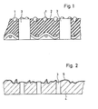
- the glass bead cloth shown in detail in Fig.l corresponds to the commercially available Spherecotetuch.
- asymmetrically scattered glass beads 1 protrude in a dome shape.
- These glass beads 1 are vulcanized into the carrier material 2 of the glass bead cloth.
- the glass beads 1 are hydrophilic, i.e. they willingly give off the color they have accepted from the freshly printed underside of the sheet. So you don't tend to build up color. This is why these glass bead domes are suitable for carrying freshly printed undersides of the bow.
- the rubber-like carrier material 2 of the glass bead cloth is oleophilic and therefore tends to build up color.
- Circular openings 3 are punched into the glass bead cloth according to FIG.
- air can be blown out or sucked in through this.
- an air cushion is generated at least between the tips of the glass beads 1, so that the freshly printed underside of the sheet only weakly comes into contact with the tops of the glass beads, thereby avoiding smearing of the fresh pressure.
- a negative pressure is created under the guided arc, as a result of which it is pressed firmly against the tops of the glass beads 1.
- a further elevator according to the invention is shown in detail in FIG. 2, namely a nickel steel sheet 4, the surface of which is roughened, for example by means of a sandblasting process, and then chrome-plated.
- the thin chrome cover layer 5 covers the entire roughened surface of the nickel steel sheet 4 serving as a support.
- the laser beams are used to burn the finest openings 3, for example with a diameter of 0.2 mm, into the elevator according to FIG.
- These breakthroughs 3 also serve to blow out air or to suck in fresh air.
- An air cushion can also be generated above the roughened surface of the elevator according to FIG.
- FIG. 3 shows a particularly advantageous embodiment of the invention.
- Elevator consisting of two layers, namely a nickel support layer 6 and a thin chrome cover layer 7, which is applied to the structured surface 8 of the nickel support layer 6.
- the structure of this structured surface 8 consists of dome-shaped wings 9 and valleys 10 between them.
- the dome-shaped wings 9 are provided asymmetrically, but statistically uniformly distributed on the structured surface 8.
- the elevator 11 according to FIG. 3 is provided with openings 3 of square cross section, which, as shown in FIG. 4, form a group.
- the side edge of the square cross section can be, for example, 0.2 mm.
- the elevator 11 according to FIG. 3 can be produced with the help of the electroplating process.
- the openings 3 can also be molded at the same time.
- the elevator 11 is stretched onto the outer surface 12 of a cylinder or a drum.
- a bore 13 is provided in this lateral surface 12, which has a diameter of approximately 2 mm and covers a group of openings 3.
- Compressed air is supplied through the bore 13 and blown out of the openings 3.
- an overpressure is formed above the chrome cover layer 7 of the elevator 11, which raises the sheet 14 to be transported to such an extent that its freshly printed underside does not come into contact with the crests of the spherical wings 9.
- openings 3 with a larger diameter, for example of approximately 2 mm, can also be provided in the elevator 11.
- Such an elevator could advantageously be used on a sheet delivery drum.
- a sheet 14 printed on both sides is transferred from the printing cylinder 15, which is drawn in sections in FIG. 6, to a transfer drum 16.
- the pressure cylinder 15 is with an elevator 11 according to FIG.
- Air channels 17 are arranged in its lateral surface 12. They run parallel to the axis of rotation of the printing cylinder 15.
- a valve disk 18 is provided on an end face of the printing cylinder 15, as shown in FIG. 7, on the side wall of the machine, not shown. It has a control slot 19 which is connected to a vacuum generator via the bore 20.
- a plurality of air channels 17 are arranged along the lateral surface 12 in a certain area and are connected to the atmosphere via bores 13.
- the elevator 11 is spanned in such a way that its groups of openings 3 each cover one bore 13 in the air channels 17.
- the printing units shown schematically in FIG. 8 are a straight printing arrangement.
- the printing unit 1 consists of the plate cylinder 21, the rubber cylinder 22 and the printing cylinder 23 with a double diameter.
- the latter is covered with elevators 11. Its design corresponds to that of the pressure cylinder 15 in Fig.6.
- the Control slot 19 causes a negative pressure generation on the surface of the elevator 11 when the sheet end has just left the pressure gap between the blanket cylinder 22 and the pressure cylinder 23. As described with reference to FIG. 6, this prevents the arch from protruding.
- a double-diameter transfer drum 16 removes the sheet from the impression cylinder 23.
- Your sheet guiding surfaces 24 can be covered with an elevator according to FIG. 1, that is to say with a glass bead cloth, which is likewise provided with openings 3 arranged over the entire surface.
- an elevator according to FIG. 1
- a glass bead cloth which is likewise provided with openings 3 arranged over the entire surface.
- air is blown out in the lower region with the aid of the control slot 19, so that the transported sheet 14 is placed against a sheet guide 26.
- the freshly printed sheet side hardly or not at all touches the surface of the glass bead cloth according to FIG. 1, which is stretched on the transfer drum 16.
- a printing cylinder 23 of the following printing unit which works together with a blanket cylinder 22 and a plate cylinder 21, takes over the sheet 14 and guides it along the printing nip, where it receives another print of a one-sided multicolor print.
- This printing cylinder 23 is also covered with elevators 11 according to FIG.
- Fig. 9 shows schematically two printing units of a perfecting machine. The whole arrangement differs from FIG. 8 only in the design of the arch guide 26 with blow holes.
- the sheet 14 guided by the printing cylinder 23 of the first printing unit is already printed one or more times on its underside.
- the pressure cylinder 23 thus leads a turned arc.
- the sheet printed on its underside receives its first impression in this printing unit.
- the sheet After passing through the printing nip and taking over the leading edge of the sheet by the transfer drum 16, it becomes precise as in FIG. 8, the sheet is pressed against the elevator 11 of the printing cylinder 23 due to a negative pressure, so that the sheet 14 cannot protrude.
- An elevator 11 according to FIG. 3 or according to FIG. 5 on a sheet delivery drum 28 can also be used particularly advantageously.
- This application is shown in Figs. 10 and 11.
- the sheet is transferred from the schematically represented printing cylinder 23 of the last printing unit to the sheet delivery drum 28 of a chain delivery unit 25.
- the end of the sheet 14 has been pulled off the blanket cylinder 22, it is prevented by suction due to the special design of the elevator 11 clamped on the impression cylinder 23.
- the gripper bridge 27 of the chain boom 25 leaves the circumference of the sheet delivery drum 28, the sheet 14 becomes a slightly different speed from the scope of the sheet delivery drum 28 imposed. This inevitably leads to a relative movement between the sheet-guiding outer surface of the sheet delivery drum 28 and the underside of the sheet 14.
- FIG. 11 shows how smearing of the freshly printed underside of the sheet is avoided by using the elevator 11 according to the invention despite the relative movement.
- the Bogenauslegetrommel 28 is provided with a plurality of blowing chambers 29, the air-saving and flow-favorable construction with the aid of foamed profile parts 31, for example, P U foam was obtained.
- the blow chambers 29 are temporarily connected to a compressed air generator (not shown) via control bores 30 and a control slot 19.
- the first printing unit consists of plate cylinder 21, blanket cylinder 22 and printing cylinder 23. This is followed by the transfer drum 33, which transfers the sheet 14 to the storage drum 34. From there, the turning cylinder 35 takes over the sheet at the front or rear edge, depending on the setting of the machine. From the turning cylinder 35, the sheet arrives at the next printing cylinder 23, which works together with the plate cylinder 21 and the blanket cylinder 23, whereby the sheet 14, depending on the setting of the machine, receives a perfecting or an impression in this printing unit.
- the single-diameter transfer drum 33 is provided with an elevator as shown in FIG. the sheet is pressed against the sheet guide 26 by means of blowing air, so that the freshly printed sheet side does not come into contact with the guide surface of the transfer drum 33.
- the storage drum 34 Due to its double diameter, the storage drum 34 is provided with two sheet guiding surfaces and has an adjustable suction box 36 in the region of the rear sheet edge. This is shown enlarged in Figure 13 and can be adjusted to the sheet format.
- the suction box 36 is connected via a pipe 37 to a vacuum generator, not shown.
- the cover plate 38 of the suction box 36 provided with bores 20 is glued with an elevator 11 according to FIG. 3. A group of openings 3 are covered by a bore 13.
- suction box 36 Sucking in the rear area of the sheet 14 by means of the suction box 36 ensures that the trailing edge of the sheet gripper of the turning cylinder 35 is taken over safely and without smearing.
- the suction box 36 thus above all prevents the sheet 14 printed on its underside from falling or falling.
- the hydrophilic surface of the elevator 11 additionally prevents the pressure on the underside of the sheet from being smeared.
- a consequent application of lifts according to the invention on all cylinders and drums of a rotary printing machine guarantees a lubrication-free, safe sheet guidance.
- blown air can be expelled briefly in a certain angular position in which the elevator does not carry a sheet, as a result of which the breakthroughs 3 of the elevator are adequately cleaned of paint and dust can.
- the suction box 36 can also be used in normal double-diameter transfer drums.
Landscapes
- Rotary Presses (AREA)
- Supply, Installation And Extraction Of Printed Sheets Or Plates (AREA)
- Coating Apparatus (AREA)
- Perforating, Stamping-Out Or Severing By Means Other Than Cutting (AREA)
- Discharging, Photosensitive Material Shape In Electrophotography (AREA)
- Printing Plates And Materials Therefor (AREA)
- Details Or Accessories Of Spraying Plant Or Apparatus (AREA)
- Manufacture Of Macromolecular Shaped Articles (AREA)
- Screen Printers (AREA)
- Paper (AREA)
- Delivering By Means Of Belts And Rollers (AREA)
- Moulding By Coating Moulds (AREA)
- Feeding Of Articles By Means Other Than Belts Or Rollers (AREA)
- Separation, Sorting, Adjustment, Or Bending Of Sheets To Be Conveyed (AREA)
- Measuring Pulse, Heart Rate, Blood Pressure Or Blood Flow (AREA)
- Other Liquid Machine Or Engine Such As Wave Power Use (AREA)
- Processing Of Solid Wastes (AREA)
Priority Applications (1)
| Application Number | Priority Date | Filing Date | Title |
|---|---|---|---|
| AT85106073T ATE50201T1 (de) | 1984-06-16 | 1985-05-17 | Folie fuer bogenfuehrende zylinder und trommeln in rotationsoffsetdruckmaschinen und verwendung derselben. |
Applications Claiming Priority (2)
| Application Number | Priority Date | Filing Date | Title |
|---|---|---|---|
| DE3422443A DE3422443C2 (de) | 1984-06-16 | 1984-06-16 | Folie für bogenführende Zylinder und Trommeln in Rotations-Offsetdruckmaschinen |
| DE3422443 | 1984-06-16 |
Publications (3)
| Publication Number | Publication Date |
|---|---|
| EP0165477A2 true EP0165477A2 (fr) | 1985-12-27 |
| EP0165477A3 EP0165477A3 (en) | 1987-10-07 |
| EP0165477B1 EP0165477B1 (fr) | 1990-02-07 |
Family
ID=6238542
Family Applications (1)
| Application Number | Title | Priority Date | Filing Date |
|---|---|---|---|
| EP85106073A Expired - Lifetime EP0165477B1 (fr) | 1984-06-16 | 1985-05-17 | Revêtement pour cylindre ou tambour transportant des feuilles dans les machines rotatives d'impression offsetet utilisation d'un tel revêtement. |
Country Status (9)
| Country | Link |
|---|---|
| US (1) | US4688784A (fr) |
| EP (1) | EP0165477B1 (fr) |
| JP (2) | JPS6111253A (fr) |
| AT (1) | ATE50201T1 (fr) |
| AU (1) | AU576848B2 (fr) |
| CA (1) | CA1238347A (fr) |
| DE (2) | DE3422443C2 (fr) |
| DK (1) | DK160605C (fr) |
| ES (1) | ES8606817A1 (fr) |
Cited By (10)
| Publication number | Priority date | Publication date | Assignee | Title |
|---|---|---|---|---|
| GB2190364A (en) * | 1986-05-14 | 1987-11-18 | Wallace Knight Ltd | An assembly for preventing the detachment of a substrate from a revolving cylinder |
| EP0878301A3 (fr) * | 1997-05-09 | 1999-06-30 | Heidelberger Druckmaschinen Aktiengesellschaft | Transport de feuilles sans maculage dans une presse rotative |
| DE4315528C2 (de) * | 1993-05-10 | 2001-10-04 | Heidelberger Druckmasch Ag | Einrichtung zur Formatanpassung einer Bogenübergabetrommel |
| DE4315514C2 (de) * | 1993-05-10 | 2001-10-31 | Heidelberger Druckmasch Ag | Einrichtung zur Formatanpassung einer Bogenübergabetrommel |
| DE4315513C2 (de) * | 1993-05-10 | 2001-11-08 | Heidelberger Druckmasch Ag | Einrichtung zur Formatanpassung einer Bogenübergabetrommel |
| GB2372543A (en) * | 2001-02-23 | 2002-08-28 | Bespak Plc | Dosage counting device |
| EP0990518B1 (fr) * | 1998-10-01 | 2003-04-16 | Heidelberger Druckmaschinen Aktiengesellschaft | Cylindre d'une machine à imprimer, notamment cylindre de contre-pression pour une machine à imprimer à feuilles rotative |
| US6684774B2 (en) | 1997-05-09 | 2004-02-03 | Heidelberger Druckmaschinen Ag | Sheet-fed rotary printing press |
| DE4315511B4 (de) * | 1993-05-10 | 2004-09-02 | Heidelberger Druckmaschinen Ag | Sauggreifer für eine Bogenübergabetrommel |
| EP1671807A3 (fr) * | 1995-12-29 | 2007-03-21 | DeMoore, Howard W. | Habillage flexible pour cylindre de transfert, anti-statique, non souillant, pré-étiré, pressé à plat, coupé avec précision et comportant une bande longitudinale |
Families Citing this family (50)
| Publication number | Priority date | Publication date | Assignee | Title |
|---|---|---|---|---|
| US4836104A (en) * | 1987-06-05 | 1989-06-06 | Duarte Products, Inc. | Sheet transfer mechanism for a freshly printed sheet |
| US4967661A (en) * | 1987-06-05 | 1990-11-06 | Duarte Procuts, Inc. | Sheet transfer mechanism for printing press |
| DE3869876D1 (de) * | 1987-09-11 | 1992-05-14 | Roland Man Druckmasch | Vorrichtung in mehrfarbenbogenrotationsdruckmaschinen zum anpressen eines bogens auf den druckzylinder. |
| DE3902923C2 (de) * | 1988-03-16 | 1994-06-01 | Heidelberger Druckmasch Ag | Bogenführungstrommel für Bogenrotationsdruckmaschinen |
| DE3827071A1 (de) * | 1988-08-10 | 1990-02-15 | Roland Man Druckmasch | Luftkissentrommel fuer bogendruckmaschinen |
| US5156090A (en) * | 1989-06-24 | 1992-10-20 | Heidelberger Druckmaschinen Ag | Device for smoothing a sheet on an impression cylinder of a sheet-fed rotary printing machine |
| DE3936846C1 (fr) * | 1989-11-06 | 1991-04-18 | Hilmar 5653 Leichlingen De Vits | |
| US5090685A (en) * | 1990-10-02 | 1992-02-25 | Optrotech Ltd. | Method and apparatus for securing a sheet material to a rotating vacuum drum using a sealing strip |
| US5127329A (en) * | 1990-12-18 | 1992-07-07 | Howard W. DeMoore | Vacuum transfer apparatus for rotary sheet-fed printing presses |
| US5205217A (en) * | 1990-12-31 | 1993-04-27 | Howard W. DeMoore | Vacuum transfer apparatus for rotary sheet-fed printing presses |
| DE4106677C1 (fr) * | 1991-03-02 | 1992-04-23 | Heidelberger Druckmaschinen Ag, 6900 Heidelberg, De | |
| US5190233A (en) * | 1991-04-12 | 1993-03-02 | Eastman Kodak Company | Apparatus for cutting and feeding strips of web material |
| DE9107437U1 (de) * | 1991-06-17 | 1991-08-22 | Erhardt + Leimer GmbH, 86157 Augsburg | Vorrichtung zum Führen einer querstabilen Bahn |
| DE4122322C2 (de) * | 1991-07-05 | 1994-03-17 | Roland Man Druckmasch | Beschichtete Papierleitwalze |
| DE4207119C2 (de) * | 1992-03-06 | 1999-09-02 | Roland Man Druckmasch | Bogenführendes Druckzylindermantelprofil |
| DE4230567C2 (de) * | 1992-09-12 | 1994-06-30 | Heidelberger Druckmasch Ag | Folie als Aufzug für einen Gegendruckzylinder einer Offset-Bogen-Rotationsdruckmaschine zum Schön- und Widerdruck |
| DE4332708C2 (de) * | 1993-09-25 | 2000-05-04 | Heidelberger Druckmasch Ag | Vorrichtung zum abschmierfreien Bogentransport in Bogendruckmaschinen |
| DE9416106U1 (de) * | 1994-10-06 | 1994-11-24 | Heidelberger Druckmaschinen Ag, 69115 Heidelberg | Bogenleitblech für eine Wendeeinrichtung |
| DE19505877C2 (de) * | 1995-02-21 | 2003-05-28 | Heidelberger Druckmasch Ag | Bogendruckmaschine |
| DE19513427C2 (de) * | 1995-04-08 | 2002-07-11 | Koenig & Bauer Ag | Bogenführungseinrichtung an Bogenführungszylindern in Druckmaschinen |
| DE19513426C2 (de) * | 1995-04-08 | 2002-07-11 | Koenig & Bauer Ag | Verfahren und Einrichtung zum Leiten von Bogen |
| JPH10754A (ja) * | 1996-06-17 | 1998-01-06 | Shinohara Tekkosho:Kk | 枚葉式印刷機の版胴 |
| US5842412A (en) * | 1997-03-07 | 1998-12-01 | Bba Nonwovens Simpsonville, Inc. | Anti-marking covering for printing press transfer cylinder |
| DE19713361B4 (de) * | 1997-03-29 | 2007-12-27 | Heidelberger Druckmaschinen Ag | Verfahren und Vorrichtung zum abschmierfreien Führen eines bedruckten Bogens auf einem bogenführenden Zylinder einer Druckmaschine, insbesondere auf einer Wendetrommel einer Bogenrotations-Offsetdruckmaschine, im Schöndruckbetrieb |
| EP0899228B1 (fr) * | 1997-08-28 | 2004-04-14 | Heidelberger Druckmaschinen Aktiengesellschaft | Dispositif de guidage à coussin d'air |
| DE19747040A1 (de) | 1997-08-28 | 1999-03-04 | Heidelberger Druckmasch Ag | Luftpolsterführung |
| DE19756942C2 (de) * | 1997-12-22 | 1999-10-07 | Heidelberger Druckmasch Ag | Druckmaschinenzylinder, insbesondere Gegendruckzylinder für eine Bogenrotationsdruckmaschine |
| US6125754A (en) * | 1998-10-30 | 2000-10-03 | Harris; J. C. | Web pressurizing channeled roller and method |
| CA2254319C (fr) * | 1998-11-18 | 2007-07-24 | Paprima Industries Inc. | Appareil de guidage de transfert de pointe directionnel |
| DE10152875B4 (de) * | 2000-11-21 | 2014-08-07 | Heidelberger Druckmaschinen Ag | Wendeeinrichtung mit Speicher für flächiges Material |
| DE10062954B4 (de) * | 2000-12-16 | 2004-04-15 | Schott Glas | Vorrichtung zum Erzeugen von Glasgobs |
| US6811863B2 (en) | 2001-07-20 | 2004-11-02 | Brite Ideas, Inc. | Anti-marking coverings for printing presses |
| DE10164255A1 (de) † | 2001-12-27 | 2003-07-17 | Heidelberger Druckmasch Ag | Drei-Trommel-Wendeeinrichtung für bogenverarbeitende Maschine |
| DE10209297A1 (de) * | 2002-03-01 | 2003-09-18 | Koenig & Bauer Ag | Oberfläche für Maschinenteile einer Druckmaschine |
| DE10304618B4 (de) * | 2002-03-25 | 2018-10-18 | Heidelberger Druckmaschinen Ag | Labyrinthdüse |
| DE10315193A1 (de) * | 2002-04-18 | 2003-10-30 | Heidelberger Druckmasch Ag | Gegendruckzylinder in einer Wendeeinrichtung einer bogenverarbeitenden Maschine |
| DE10217709A1 (de) * | 2002-04-20 | 2003-11-06 | Koenig & Bauer Ag | Bogenleiteinrichtung |
| DE10217708A1 (de) * | 2002-04-20 | 2003-11-06 | Koenig & Bauer Ag | Bogenleiteinrichtung |
| DE10305422B4 (de) * | 2003-02-05 | 2006-01-19 | Schott Ag | Verfahren zur Herstellung von Kugeln mit optischer Qualität aus zähem Glas |
| DE102004055315A1 (de) * | 2004-11-16 | 2006-05-18 | Man Roland Druckmaschinen Ag | Mehrfarbendruckmaschine und Verfahren zum Betreiben einer Mehrfarbendruckmaschine |
| AU2007249795B2 (en) | 2006-05-12 | 2012-06-28 | Printguard, Inc. | Fixture for anti-marking coverings for printing presses |
| JP5225623B2 (ja) * | 2006-07-12 | 2013-07-03 | ハイデルベルガー ドルツクマシーネン アクチエンゲゼルシヤフト | 被印刷体と接触する部材を製造する方法 |
| DE102008021694A1 (de) * | 2008-04-30 | 2009-11-05 | Koenig & Bauer Aktiengesellschaft | Flächenelement mit einer hohen Formstabilität für Druckmaschinen und Verfahren zu seiner Herstellung |
| US8863939B2 (en) * | 2009-12-14 | 2014-10-21 | Xerox Corporation | Surface roughness for improved vacuum pressure for efficient media hold-down performance |
| US8695783B2 (en) * | 2009-12-14 | 2014-04-15 | Xerox Corporation | Vacuum transport belts |
| US8708135B2 (en) * | 2009-12-14 | 2014-04-29 | Xerox Corporation | Vacuum transport belts |
| DE102010001685A1 (de) * | 2010-02-09 | 2011-08-11 | manroland AG, 63075 | Wendeeinrichtung einer Bogendruckmaschine |
| DE102012216324B4 (de) | 2011-09-19 | 2023-01-05 | Koenig & Bauer Ag | Bogenverarbeitende Maschine und Verfahren zum Transport von Bogen |
| EP3063007B1 (fr) * | 2013-10-28 | 2020-08-05 | HP Indigo B.V. | Dispositif et procédé pour l'application d'un fluide sur un substrat |
| DE102015209699B4 (de) * | 2015-05-27 | 2018-06-07 | Koenig & Bauer Ag | Wendevorrichtung und Verfahren zum Wenden eines Bogens mit einem Bogenführungszylinder und einer an den Bogenführungszylinder angestellten Ablöseeinrichtung |
Family Cites Families (27)
| Publication number | Priority date | Publication date | Assignee | Title |
|---|---|---|---|---|
| US3126826A (en) * | 1964-03-31 | Transfer cylinder for rotary multi-color printing presses | ||
| DE220801C (fr) * | ||||
| US2061033A (en) * | 1933-11-29 | 1936-11-17 | Alexander T Koppe | Sheet transfer mechanism for printing presses |
| DE665310C (de) * | 1935-08-21 | 1938-09-22 | Dresden Leipziger Schnellpress | Bogenausfuehrvorrichtung fuer Druckmaschinen |
| DE728119C (de) * | 1935-08-21 | 1942-11-20 | Planeta Druckmaschinenwerk Ag | Bogenausfuehrvorrichtung fuer Druckmaschinen |
| US2730950A (en) * | 1954-07-26 | 1956-01-17 | Leon J Grassi | Air pressure system for the skeleton wheels of an off-set printing press |
| DE1011438B (de) * | 1955-02-26 | 1957-07-04 | Falz Und Heftmaschinenwerk Veb | Saugelement an Bogenanlegern |
| US3161130A (en) * | 1963-05-27 | 1964-12-15 | Miller Printing Machinery Co | Printing apparatus |
| DE1561043B1 (de) * | 1967-03-16 | 1970-03-05 | Roland Offsetmaschf | Auslegertrommel |
| GB1218801A (en) * | 1967-05-12 | 1971-01-13 | Masson Scott Thrissell Eng Ltd | Improvements in web guide members |
| DE2026355B1 (de) * | 1970-05-29 | 1971-11-18 | Roland Offsetmaschinenfabrik Faber & Schleicher Ag, 6050 Offenbach | Wendestange zum Umlenken von Papierbahnen |
| US3913478A (en) * | 1971-06-17 | 1975-10-21 | Nebiolo Spa | Printing press with variable speed transfer cylinder |
| US3835597A (en) * | 1972-11-24 | 1974-09-17 | Harris Intertype Corp | Method of manufacturing a hydrophilic dampening roll |
| DE2358206C3 (de) * | 1973-11-22 | 1979-10-04 | Roland Offsetmaschinenfabrik Faber & Schleicher Ag, 6050 Offenbach | Vorrichtung an Druckmaschinen zum Transport von Bogen |
| DE2443663C3 (de) * | 1974-09-12 | 1981-01-15 | Basf Ag, 6700 Ludwigshafen | Walzeneinrichtung zum fortlaufenden Transport von Folienbahnen |
| DE2446188C3 (de) * | 1974-09-27 | 1983-11-24 | Heidelberger Druckmaschinen Ag, 6900 Heidelberg | Bogenführende Mantelfläche von Gegendruckzylindern oder Bogenüberführungszylindern in Rotationsoffsetdruckmaschinen |
| CH578940A5 (fr) * | 1975-02-14 | 1976-08-31 | Von Roll Ag | |
| CH598110A5 (fr) * | 1975-10-10 | 1978-04-28 | Gretag Ag | |
| US4099463A (en) * | 1977-04-13 | 1978-07-11 | Veb Polygraph Leipzig Kombinat Fuer Polygraphische Maschinen Und Ausruestungen | Support arrangement for guiding sheets through a printing machine |
| US4207998A (en) * | 1977-05-16 | 1980-06-17 | Bachofen & Meier, Maschinenfabrik | Vacuum roller |
| JPS609031Y2 (ja) * | 1978-06-26 | 1985-04-01 | 株式会社サト−研究所 | ハンドラベラ−用の印字装置 |
| DE7911947U1 (de) * | 1979-04-24 | 1984-05-30 | Heidelberger Druckmaschinen Ag, 6900 Heidelberg | Bogenfuehrende folie als aufzug fuer gegendruckzylinder |
| DE2916505A1 (de) * | 1979-04-24 | 1980-10-30 | Heidelberger Druckmasch Ag | Bogenfuehrende folie als aufzug fuer gegendruckzylinder |
| AT367233B (de) * | 1980-04-04 | 1982-06-11 | Philips Nv | Bandfuehrung |
| JPS5726754U (fr) * | 1980-07-22 | 1982-02-12 | ||
| DE3036790C2 (de) * | 1980-09-30 | 1982-11-11 | Heidelberger Druckmaschinen Ag, 6900 Heidelberg | Bogenübergabetrommel für auf Schön- und Widerdruck umstellbare Bogenrotationsdruckmaschinen |
| DE3209259C1 (de) * | 1982-03-13 | 1983-11-03 | M.A.N.- Roland Druckmaschinen AG, 6050 Offenbach | Bogenanlegevorrichtung an bogenverarbeitenden Maschinen |
-
1984
- 1984-06-16 DE DE3422443A patent/DE3422443C2/de not_active Expired
-
1985
- 1985-04-26 AU AU41715/85A patent/AU576848B2/en not_active Ceased
- 1985-05-07 CA CA000480972A patent/CA1238347A/fr not_active Expired
- 1985-05-13 ES ES543100A patent/ES8606817A1/es not_active Expired
- 1985-05-17 DE DE8585106073T patent/DE3575888D1/de not_active Expired - Lifetime
- 1985-05-17 AT AT85106073T patent/ATE50201T1/de not_active IP Right Cessation
- 1985-05-17 EP EP85106073A patent/EP0165477B1/fr not_active Expired - Lifetime
- 1985-05-22 DK DK227485A patent/DK160605C/da not_active IP Right Cessation
- 1985-06-17 JP JP60130075A patent/JPS6111253A/ja active Pending
- 1985-06-17 US US06/745,696 patent/US4688784A/en not_active Expired - Lifetime
-
1994
- 1994-08-29 JP JP010686U patent/JPH0721344U/ja active Pending
Cited By (12)
| Publication number | Priority date | Publication date | Assignee | Title |
|---|---|---|---|---|
| GB2190364A (en) * | 1986-05-14 | 1987-11-18 | Wallace Knight Ltd | An assembly for preventing the detachment of a substrate from a revolving cylinder |
| DE4315528C2 (de) * | 1993-05-10 | 2001-10-04 | Heidelberger Druckmasch Ag | Einrichtung zur Formatanpassung einer Bogenübergabetrommel |
| DE4315514C2 (de) * | 1993-05-10 | 2001-10-31 | Heidelberger Druckmasch Ag | Einrichtung zur Formatanpassung einer Bogenübergabetrommel |
| DE4315513C2 (de) * | 1993-05-10 | 2001-11-08 | Heidelberger Druckmasch Ag | Einrichtung zur Formatanpassung einer Bogenübergabetrommel |
| DE4315511B4 (de) * | 1993-05-10 | 2004-09-02 | Heidelberger Druckmaschinen Ag | Sauggreifer für eine Bogenübergabetrommel |
| EP1671807A3 (fr) * | 1995-12-29 | 2007-03-21 | DeMoore, Howard W. | Habillage flexible pour cylindre de transfert, anti-statique, non souillant, pré-étiré, pressé à plat, coupé avec précision et comportant une bande longitudinale |
| EP0878301A3 (fr) * | 1997-05-09 | 1999-06-30 | Heidelberger Druckmaschinen Aktiengesellschaft | Transport de feuilles sans maculage dans une presse rotative |
| US6684774B2 (en) | 1997-05-09 | 2004-02-03 | Heidelberger Druckmaschinen Ag | Sheet-fed rotary printing press |
| EP0990518B1 (fr) * | 1998-10-01 | 2003-04-16 | Heidelberger Druckmaschinen Aktiengesellschaft | Cylindre d'une machine à imprimer, notamment cylindre de contre-pression pour une machine à imprimer à feuilles rotative |
| US6581517B1 (en) | 1998-10-01 | 2003-06-24 | Heidelberger Druckmaschinen Ag | Printing-machine cylinder, especially an impression cylinder, for a sheet-fed rotary printing machine, and method of production |
| GB2372543A (en) * | 2001-02-23 | 2002-08-28 | Bespak Plc | Dosage counting device |
| GB2372543B (en) * | 2001-02-23 | 2003-08-20 | Bespak Plc | Dosage counting devices |
Also Published As
| Publication number | Publication date |
|---|---|
| EP0165477A3 (en) | 1987-10-07 |
| US4688784A (en) | 1987-08-25 |
| ATE50201T1 (de) | 1990-02-15 |
| JPH0721344U (ja) | 1995-04-18 |
| AU4171585A (en) | 1985-12-19 |
| DK160605B (da) | 1991-04-02 |
| EP0165477B1 (fr) | 1990-02-07 |
| JPS6111253A (ja) | 1986-01-18 |
| DK227485A (da) | 1985-12-17 |
| DE3575888D1 (de) | 1990-03-15 |
| ES543100A0 (es) | 1986-05-16 |
| DK160605C (da) | 1991-09-02 |
| DK227485D0 (da) | 1985-05-22 |
| DE3422443C2 (de) | 1989-11-23 |
| ES8606817A1 (es) | 1986-05-16 |
| AU576848B2 (en) | 1988-09-08 |
| CA1238347A (fr) | 1988-06-21 |
| DE3422443A1 (de) | 1985-12-19 |
Similar Documents
| Publication | Publication Date | Title |
|---|---|---|
| EP0165477B1 (fr) | Revêtement pour cylindre ou tambour transportant des feuilles dans les machines rotatives d'impression offsetet utilisation d'un tel revêtement. | |
| DE2446188C3 (de) | Bogenführende Mantelfläche von Gegendruckzylindern oder Bogenüberführungszylindern in Rotationsoffsetdruckmaschinen | |
| DE3419762C2 (fr) | ||
| DE3411029C2 (fr) | ||
| DE19704003A1 (de) | Verfahren und Vorrichtung zum Eindrucken von individualisierenden Kennzeichnungen | |
| EP0343105A2 (fr) | Rotative à plusieurs couleurs pour imprimer recto-verso simultanément | |
| DE19804269A1 (de) | Vorrichtung zum Auftragen einer Flüssigkeit auf einen Bedruckstoffbogen, insbesondere Druck, oder Lackierwerk, in einer Bogenrotationsdruckmaschine | |
| EP1737659B1 (fr) | Garniture pour dispositif d'estampage | |
| EP0706881A1 (fr) | Système de guidage de feuilles dans le dispositif de retournement d'une machine à imprimer recto-verso | |
| EP1037748A1 (fr) | Procede pour imprimer des feuilles | |
| DE3248232C1 (de) | Druckmaschine zum Bedrucken und abschliessenden Lackieren von Bogen | |
| DE102019118568A1 (de) | Bogenverarbeitende Maschine mit einer Wendeeinrichtung und Verfahren zum Fördern von Bogen | |
| DE102019118565B4 (de) | Bogenverarbeitende Maschine und Verfahren zum Fördern von Bogen | |
| DE19513426C2 (de) | Verfahren und Einrichtung zum Leiten von Bogen | |
| DE2603483B2 (de) | Verfahren zum Führen eines Bogens zum gleichzeitigen Bedrucken mit einem Schön- und Widerdruck sowie Vorrichtung zur Durchführung des Verfahrens | |
| EP0158129B1 (fr) | Rotative pour feuilles pour imprimer à retiration ou en plusieurs couleurs | |
| DE4219116A1 (de) | Bogenrotationsdruckmaschine für Mehrfarbendruck | |
| EP0150355B1 (fr) | Procédé d'impression à retiration et machine d'impression offset à feuilles pour la mise en oeuvre du procédé | |
| DE102006030062B3 (de) | Bogenführungszylinder mit Aufzug in einer Verarbeitungsmaschine | |
| DE8418300U1 (de) | Aufzug für bogenführende Zylinder und Trommeln in Rotations-Offsetdruckmaschinen | |
| DE10115876A1 (de) | Farbabweisende Beschichtung für ein einen Bedruckstoff kontaktierendes Element | |
| EP1124689B1 (fr) | Systeme de guidage de feuilles dans une machine a imprimer | |
| DE102019118566B4 (de) | Bogenverarbeitende Maschine und Verfahren zum Fördern von Bogen | |
| DE20303720U1 (de) | Bahnführung in einer Rollenrotatinsdruckmaschine | |
| DE10023136A1 (de) | Bogenrotationsdruckmaschine für Mehrfarbendruck |
Legal Events
| Date | Code | Title | Description |
|---|---|---|---|
| PUAI | Public reference made under article 153(3) epc to a published international application that has entered the european phase |
Free format text: ORIGINAL CODE: 0009012 |
|
| 17P | Request for examination filed |
Effective date: 19850517 |
|
| AK | Designated contracting states |
Designated state(s): AT BE CH DE FR GB IT LI NL SE |
|
| PUAL | Search report despatched |
Free format text: ORIGINAL CODE: 0009013 |
|
| AK | Designated contracting states |
Kind code of ref document: A3 Designated state(s): AT BE CH DE FR GB IT LI NL SE |
|
| 17Q | First examination report despatched |
Effective date: 19890201 |
|
| GRAA | (expected) grant |
Free format text: ORIGINAL CODE: 0009210 |
|
| AK | Designated contracting states |
Kind code of ref document: B1 Designated state(s): AT BE CH DE FR GB IT LI NL SE |
|
| REF | Corresponds to: |
Ref document number: 50201 Country of ref document: AT Date of ref document: 19900215 Kind code of ref document: T |
|
| REF | Corresponds to: |
Ref document number: 3575888 Country of ref document: DE Date of ref document: 19900315 |
|
| ET | Fr: translation filed | ||
| ITF | It: translation for a ep patent filed | ||
| GBT | Gb: translation of ep patent filed (gb section 77(6)(a)/1977) | ||
| PLBI | Opposition filed |
Free format text: ORIGINAL CODE: 0009260 |
|
| 26 | Opposition filed |
Opponent name: MAN ROLAND DRUCKMASCHINEN AG Effective date: 19901105 |
|
| NLR1 | Nl: opposition has been filed with the epo |
Opponent name: MAN ROLAND DRUCKMASCHINEN AG. |
|
| ITTA | It: last paid annual fee | ||
| PLBN | Opposition rejected |
Free format text: ORIGINAL CODE: 0009273 |
|
| STAA | Information on the status of an ep patent application or granted ep patent |
Free format text: STATUS: OPPOSITION REJECTED |
|
| 27O | Opposition rejected |
Effective date: 19921106 |
|
| PGFP | Annual fee paid to national office [announced via postgrant information from national office to epo] |
Ref country code: AT Payment date: 19930428 Year of fee payment: 9 |
|
| NLR2 | Nl: decision of opposition | ||
| PGFP | Annual fee paid to national office [announced via postgrant information from national office to epo] |
Ref country code: BE Payment date: 19930517 Year of fee payment: 9 |
|
| PGFP | Annual fee paid to national office [announced via postgrant information from national office to epo] |
Ref country code: SE Payment date: 19930519 Year of fee payment: 9 |
|
| PGFP | Annual fee paid to national office [announced via postgrant information from national office to epo] |
Ref country code: NL Payment date: 19930531 Year of fee payment: 9 |
|
| PG25 | Lapsed in a contracting state [announced via postgrant information from national office to epo] |
Ref country code: AT Effective date: 19940517 |
|
| PG25 | Lapsed in a contracting state [announced via postgrant information from national office to epo] |
Ref country code: SE Effective date: 19940518 |
|
| PG25 | Lapsed in a contracting state [announced via postgrant information from national office to epo] |
Ref country code: BE Effective date: 19940531 |
|
| BERE | Be: lapsed |
Owner name: HEIDELBERGER DRUCKMASCHINEN A.G. Effective date: 19940531 |
|
| PG25 | Lapsed in a contracting state [announced via postgrant information from national office to epo] |
Ref country code: NL Effective date: 19941201 |
|
| NLV4 | Nl: lapsed or anulled due to non-payment of the annual fee | ||
| EUG | Se: european patent has lapsed |
Ref document number: 85106073.1 Effective date: 19941210 |
|
| EUG | Se: european patent has lapsed |
Ref document number: 85106073.1 |
|
| PGFP | Annual fee paid to national office [announced via postgrant information from national office to epo] |
Ref country code: FR Payment date: 19950503 Year of fee payment: 11 |
|
| PGFP | Annual fee paid to national office [announced via postgrant information from national office to epo] |
Ref country code: CH Payment date: 19950613 Year of fee payment: 11 |
|
| PG25 | Lapsed in a contracting state [announced via postgrant information from national office to epo] |
Ref country code: LI Effective date: 19960531 Ref country code: CH Effective date: 19960531 |
|
| REG | Reference to a national code |
Ref country code: CH Ref legal event code: PL |
|
| PG25 | Lapsed in a contracting state [announced via postgrant information from national office to epo] |
Ref country code: FR Effective date: 19970131 |
|
| REG | Reference to a national code |
Ref country code: FR Ref legal event code: ST |
|
| REG | Reference to a national code |
Ref country code: GB Ref legal event code: IF02 |
|
| PGFP | Annual fee paid to national office [announced via postgrant information from national office to epo] |
Ref country code: GB Payment date: 20020425 Year of fee payment: 18 |
|
| PGFP | Annual fee paid to national office [announced via postgrant information from national office to epo] |
Ref country code: DE Payment date: 20020604 Year of fee payment: 18 |
|
| PG25 | Lapsed in a contracting state [announced via postgrant information from national office to epo] |
Ref country code: GB Free format text: LAPSE BECAUSE OF NON-PAYMENT OF DUE FEES Effective date: 20030517 |
|
| PG25 | Lapsed in a contracting state [announced via postgrant information from national office to epo] |
Ref country code: DE Free format text: LAPSE BECAUSE OF NON-PAYMENT OF DUE FEES Effective date: 20031202 |
|
| GBPC | Gb: european patent ceased through non-payment of renewal fee |
Effective date: 20030517 |