EP0165488A2 - Procédé de transmission d'images de télévision - Google Patents
Procédé de transmission d'images de télévision Download PDFInfo
- Publication number
- EP0165488A2 EP0165488A2 EP85106162A EP85106162A EP0165488A2 EP 0165488 A2 EP0165488 A2 EP 0165488A2 EP 85106162 A EP85106162 A EP 85106162A EP 85106162 A EP85106162 A EP 85106162A EP 0165488 A2 EP0165488 A2 EP 0165488A2
- Authority
- EP
- European Patent Office
- Prior art keywords
- signal values
- values
- transformation
- transmitted
- spectral values
- Prior art date
- Legal status (The legal status is an assumption and is not a legal conclusion. Google has not performed a legal analysis and makes no representation as to the accuracy of the status listed.)
- Granted
Links
Images


Classifications
-
- H—ELECTRICITY
- H04—ELECTRIC COMMUNICATION TECHNIQUE
- H04N—PICTORIAL COMMUNICATION, e.g. TELEVISION
- H04N19/00—Methods or arrangements for coding, decoding, compressing or decompressing digital video signals
- H04N19/60—Methods or arrangements for coding, decoding, compressing or decompressing digital video signals using transform coding
Definitions
- the invention relates to a method for the transmission of digitized television pictures, in which the signal values of partial pictures are transformed overlapping into spectral values, the coefficients of which are transmitted and from which the signal values are in turn determined on the receiving side by reverse transformation.
- the image signals of partial images are converted into spectral values, the coefficients of which are transmitted and converted back into the corresponding signal values (luminance and chrominance) on the receiving side by reverse transformation.
- Errors that arise due to the falsification of the spectral values are barely perceived, since the energy of the interference affects the entire partial image, that is to say, all of the spectral values, distributed. Since some of the spectral values only contain a small amount of energy, further data reduction is possible through suitable quantization.
- partial images can be one-dimensional, for example include the luminance signals of part of a television line, be two-dimensional, i.e. take into account the adjacent signal values from previous television lines or the corresponding signal values of the same pixels of the previous television image, or, with appropriate effort, be three-dimensional and two-dimensional partial images and that take into account the previous television field.
- window functions in the implementation of filters is also known.
- the spline functions are described in detail in Ahlberg's book, The Theory of Splines and Their Applications, Academic Press New York, London. Their application in filter implementation is described in the article "On spline interpolation in digital filters” in Frequency 38 (1984), pp. 44-49.
- the object of the invention is to provide an improved transformation method for the transmission of digital television pictures.
- this object is achieved in that a plurality of fields with N signal values each are evaluated on the transmission side using a time window function, that several fields with N signal values each using a modified Fourier transform, the N coefficients of which are an integer number of sine oscillation periods, are converted into spectral values, that only a maximum of N spectral values are transmitted, that the corresponding overlapping processing then takes place on the transmission side - apart from the first partial image - several partial images and a further partial image, that the non-transmitted spectral values are received on the receiving side by interpolation of the transmitted Spectral values are determined that all spectral values are subsequently transformed back and that the image signal values to be used further are added by adding the evaluated signal values obtained by reverse transformation to the can be determined in accordance with the overlapping processing on the transmission side of evaluated signal values.
- a "transfer function" for the coefficients that is as rectangular as possible is defined (with little leakage to neighboring coefficients), the so-called picket fence effect being intended to remain small due to a suitable bandwidth.
- the corresponding time window function - this corresponds to the reverse transformation of the transfer function - will be as short as possible for reasons of complexity and should cover the time axis constantly during the transfer with a predetermined feed.
- Spline functions are advantageous for this. Due to the transformation used, only a few spectral values are generated and transmitted. The spectral values required for the reverse transformation are recovered by interpolation. The data rate is further reduced by quantizing the spectral values.
- the discrete Fourier transformation has favorable transformation properties and is easy to implement.
- m hi (often referred to as basic vectors) are used again, which comprise an integer number of sinusoidal oscillation periods with a constant h for each N coefficient.
- N 6 signal values, which correspond, for example, to the luminance values of pixels.
- the processing is explained in more detail using the basic circuit diagram in FIG. 2.
- the signal values X present at input 1 of a series-parallel converter 2 are first converted into parallel form with a width of 4N signal words. Then a simultaneous evaluation of all 4N signal values takes place by means of a time window function w (t) in a time window function multiplier 3.
- the series-parallel conversion of a new field B5 then takes place.
- This and the last three partial images B2 to B4 are evaluated together with the same time window function w (t).
- the evaluated signal values XB, again comprising 4N, are converted into spectral values YT in the transformation device 4. Not all possible 4N, but only N selected spectral values YT are transmitted.
- the transformation results in a data reduction by breaking the statistical links between the image signals.
- the spectral values are fed to a coding device 5, which carries out quantization and coding. This results in a further data reduction, which, however, is not part of the present invention.
- Decoding is first carried out on the receiving side by a decoding device 6.
- Y 4N spectral values are available.
- These are fed to a reverse transformation device 8, which on their Output in turn 4N signal values XT evaluated according to the time function w (t) results which largely correspond to the evaluated signal values XB.
- the signal values of the three first inversely transformed partial images B2, B3 and B4 are each converted into the corresponding already inversely transformed signal values of the same partial images (B) a - added data block added.
- Each sub-picture is thus composed of signal values which consist of adding four signal values XT obtained by reverse transformation.
- a complete field with the image signal values X * to be used is present at the output of the addition device 9, which is output in serial form by a parallel-series converter 10 at its output 11.
- the time window function w (t) should be as short as possible and an overlap with a feed interval T, which corresponds to a partial image B, should cover the time axis constantly.
- time window function w (t) which arise by folding a defined rectangular window w OT with itself and the length (m + 1) T to have.
- the basis vectors of the transformation can thus be specified with the aid of the displacement theorem, as shown in FIG. 5.
- the selected division of the frequency band leads to a real Fourier transformation with the rectangular matrix
- the transformation can be carried out with the help of an LSI module; other known circuits can also be used.
- 4N spectral values Y must again be obtained from the N spectral values YT obtained by transformation are determined, from which the signal values X are in turn determined by inverse transformation through the full square DFT matrix M 0 -1 .
- the zeroth, fourth, eighth, twelfth etc. line of the transformation matrix M O was used to convert the signal values into spectral values, corresponding to the time window function comprising four fields (if the time window function comprises 5 fields, every fifth line of the corresponding matrix M O.
- the missing spectral values are obtained at the receiving end by interpolation between the transmitted spectral values YT. Even linear interpolation brings favorable results.
- the inverse transformation is carried out using the inverse DFT matrix M 0 -1
- the back-transformed signal values XT differ from the signal values XB evaluated with the time window function due to quantization and interpolation errors. Very small spectral values can be disregarded during the transmission and the back transformation. It is also conceivable to disregard the higher-order spectral values, to a certain extent the high-frequency components.
- the back-transformed signal values XT are combined by sliding addition to the original image signal values X * . This is done in the addition device 9, which contains, for example, a 4N long register with the word width required for the signal values.
- the continuous addition results in the image signal values X * in accordance with the presumed time window functions, which differ slightly from the original signal values X due to the data reductions made.
- At the output of the adder there is a complete field with N signal values, which is converted into serial form by the parallel-series converter 10.
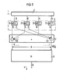
- FIG. 7 A simplified transmission device is shown in FIG. 7. It again contains the series-parallel converter 2 and the time function multiplier 3, which is shown in more detail here. It contains four sub-function multipliers 31 to 34, in each of which a section w (t) 1 to w (t) 4 of the time window function according to FIG. 3, for example between T and 2T, is implemented.
- the corresponding signal values of each field are combined in a further addition device 12, for example all first signal values in a first adder 121, all Nth signal values in an adder 12N, etc., so that sum signal values XBS are present at the output, each value of which is used in this example Contains the sum of 4 corresponding signal values from 4 successive fields, all of which were evaluated in accordance with the time window function w (t).
- the transformation can now be carried out using the matrix M, which has N columns and N rows.
- the modified transformation device 41 accordingly also has only N inputs.
- a further improvement in data reduction is made more multidimensional, usually at most, by the transmission three-dimensional drawing files.
- the evaluation is first carried out in one direction by means of a time window function and transformation, then a corresponding procedure takes place in the second and in every further direction.
Landscapes
- Engineering & Computer Science (AREA)
- Multimedia (AREA)
- Signal Processing (AREA)
- Color Television Systems (AREA)
- Television Systems (AREA)
- Two-Way Televisions, Distribution Of Moving Picture Or The Like (AREA)
- Reduction Or Emphasis Of Bandwidth Of Signals (AREA)
- Apparatus For Radiation Diagnosis (AREA)
Priority Applications (1)
| Application Number | Priority Date | Filing Date | Title |
|---|---|---|---|
| AT85106162T ATE51991T1 (de) | 1984-05-21 | 1985-05-20 | Verfahren zur uebertragung von fernsehbildern. |
Applications Claiming Priority (2)
| Application Number | Priority Date | Filing Date | Title |
|---|---|---|---|
| DE3418858 | 1984-05-21 | ||
| DE3418858 | 1984-05-21 |
Publications (3)
| Publication Number | Publication Date |
|---|---|
| EP0165488A2 true EP0165488A2 (fr) | 1985-12-27 |
| EP0165488A3 EP0165488A3 (en) | 1986-01-15 |
| EP0165488B1 EP0165488B1 (fr) | 1990-04-11 |
Family
ID=6236444
Family Applications (1)
| Application Number | Title | Priority Date | Filing Date |
|---|---|---|---|
| EP85106162A Expired - Lifetime EP0165488B1 (fr) | 1984-05-21 | 1985-05-20 | Procédé de transmission d'images de télévision |
Country Status (4)
| Country | Link |
|---|---|
| EP (1) | EP0165488B1 (fr) |
| JP (1) | JPS6143888A (fr) |
| AT (1) | ATE51991T1 (fr) |
| DE (1) | DE3577172D1 (fr) |
Cited By (1)
| Publication number | Priority date | Publication date | Assignee | Title |
|---|---|---|---|---|
| DE3914267A1 (de) * | 1989-04-29 | 1990-10-31 | Thomson Brandt Gmbh | Signalverarbeitungssystem fuer digitalsignale |
Family Cites Families (2)
| Publication number | Priority date | Publication date | Assignee | Title |
|---|---|---|---|---|
| FR2329124A1 (fr) * | 1975-10-24 | 1977-05-20 | Telecommunications Sa | Codeur-decodeur d'images a transformee matricielle avec ponderation des contributions des points de l'image a la formation de la transformee |
| DE3369451D1 (en) * | 1982-10-14 | 1987-02-26 | British Telecomm | Image transmission |
-
1985
- 1985-05-20 AT AT85106162T patent/ATE51991T1/de active
- 1985-05-20 EP EP85106162A patent/EP0165488B1/fr not_active Expired - Lifetime
- 1985-05-20 DE DE8585106162T patent/DE3577172D1/de not_active Expired - Lifetime
- 1985-05-21 JP JP60107098A patent/JPS6143888A/ja active Pending
Cited By (2)
| Publication number | Priority date | Publication date | Assignee | Title |
|---|---|---|---|---|
| DE3914267A1 (de) * | 1989-04-29 | 1990-10-31 | Thomson Brandt Gmbh | Signalverarbeitungssystem fuer digitalsignale |
| WO1990013971A1 (fr) * | 1989-04-29 | 1990-11-15 | Deutsche Thomson-Brandt Gmbh | Systeme de traitement de signaux numeriques |
Also Published As
| Publication number | Publication date |
|---|---|
| DE3577172D1 (de) | 1990-05-17 |
| ATE51991T1 (de) | 1990-04-15 |
| EP0165488B1 (fr) | 1990-04-11 |
| EP0165488A3 (en) | 1986-01-15 |
| JPS6143888A (ja) | 1986-03-03 |
Similar Documents
| Publication | Publication Date | Title |
|---|---|---|
| DE3044208C2 (de) | Interpolator zur Erhöhung der Wortgeschwindigkeit eines digitalen Signals | |
| DE2640140C2 (de) | Verfahren und Anordnung zur redundanzvermindernden Bildcodierung | |
| DE69411470T2 (de) | Methode und Vorrichtung zur Verbesserung der Schärfe einer einem kontinuierlichem Zoom unterworfenen Bildfolge | |
| DE2640157C2 (de) | Verfahren und Anordnung zum redundanzvermindernden Codieren von Bildern | |
| DE3788997T3 (de) | Interpolation von Zeilen eines Videosignals. | |
| DE4241131B4 (de) | Einrichtung zum Kodieren und Dekodieren von Übertragungssignalen mittels Transformationen | |
| DE3124653C2 (fr) | ||
| DE69221228T2 (de) | Adaptives Filterverfahren eines in Teilbändern transformierten Signals und entsprechende Filteranordnung | |
| DE2811576C2 (de) | Übertragungsanordnung mit Umwandlung diskreter Signale in ein diskretes Einseitenband-Frequenzmultiplexsignal und umgekehrt | |
| DE2707936C3 (de) | Einseitenband-FrequenzmultiplexÜbertragungssystem | |
| DE69424923T2 (de) | Verfahren und Anordnung zur Bearbeitung eines dekodierten Bildsignals mit Verzerrung | |
| DE2831059C2 (de) | Integrierender Kodeumsetzer | |
| EP0494990B1 (fr) | Procede pour transmettre un signal | |
| DE2616660B2 (de) | Arithmetische Einheit | |
| DE2216350C3 (de) | Digitalfilter | |
| DE2837120A1 (de) | Verfahren und anordnung zur verarbeitung von pal-farbfernsehsignalen in digitaler form | |
| EP0255931B1 (fr) | Procédé de transmission d'un signal vidéo | |
| DE3810916C2 (de) | Delta-Pulscodemodulation | |
| DE2315347A1 (de) | Verfahren und vorrichtung zur fortlaufenden decodierung von gruppen bildenden signalen | |
| DE2850718A1 (de) | Sich selbst anpassender entzerrer fuer eine elektrische nachrichtenuebertragungsstrecke | |
| DE69636139T2 (de) | Hierarchische Kodierungs- Dekodierungs-Vorrictung mit Speichervorrichtung für ein digitales Bildsignal | |
| DE69403328T2 (de) | Verfahren und vorrichtung zum filtern eines digitalen zeitsignals und anwendung für echokorrektur in einem übertragungskanal | |
| DE3545106C2 (fr) | ||
| EP0165488B1 (fr) | Procédé de transmission d'images de télévision | |
| DE3883414T2 (de) | Digitales Signalverarbeitungssystem mit einer Filterbank. |
Legal Events
| Date | Code | Title | Description |
|---|---|---|---|
| PUAI | Public reference made under article 153(3) epc to a published international application that has entered the european phase |
Free format text: ORIGINAL CODE: 0009012 |
|
| PUAL | Search report despatched |
Free format text: ORIGINAL CODE: 0009013 |
|
| AK | Designated contracting states |
Designated state(s): AT BE CH DE FR GB IT LI NL SE |
|
| AK | Designated contracting states |
Designated state(s): AT BE CH DE FR GB IT LI NL SE |
|
| 17P | Request for examination filed |
Effective date: 19860205 |
|
| 17Q | First examination report despatched |
Effective date: 19880909 |
|
| GRAA | (expected) grant |
Free format text: ORIGINAL CODE: 0009210 |
|
| AK | Designated contracting states |
Kind code of ref document: B1 Designated state(s): AT BE CH DE FR GB IT LI NL SE |
|
| PG25 | Lapsed in a contracting state [announced via postgrant information from national office to epo] |
Ref country code: SE Effective date: 19900411 Ref country code: NL Effective date: 19900411 Ref country code: IT Free format text: LAPSE BECAUSE OF FAILURE TO SUBMIT A TRANSLATION OF THE DESCRIPTION OR TO PAY THE FEE WITHIN THE PRESCRIBED TIME-LIMIT;WARNING: LAPSES OF ITALIAN PATENTS WITH EFFECTIVE DATE BEFORE 2007 MAY HAVE OCCURRED AT ANY TIME BEFORE 2007. THE CORRECT EFFECTIVE DATE MAY BE DIFFERENT FROM THE ONE RECORDED. Effective date: 19900411 Ref country code: GB Effective date: 19900411 Ref country code: FR Effective date: 19900411 Ref country code: BE Effective date: 19900411 |
|
| REF | Corresponds to: |
Ref document number: 51991 Country of ref document: AT Date of ref document: 19900415 Kind code of ref document: T |
|
| REF | Corresponds to: |
Ref document number: 3577172 Country of ref document: DE Date of ref document: 19900517 |
|
| PG25 | Lapsed in a contracting state [announced via postgrant information from national office to epo] |
Ref country code: AT Effective date: 19900520 |
|
| PG25 | Lapsed in a contracting state [announced via postgrant information from national office to epo] |
Ref country code: LI Effective date: 19900531 Ref country code: CH Effective date: 19900531 |
|
| EN | Fr: translation not filed | ||
| NLV1 | Nl: lapsed or annulled due to failure to fulfill the requirements of art. 29p and 29m of the patents act | ||
| GBV | Gb: ep patent (uk) treated as always having been void in accordance with gb section 77(7)/1977 [no translation filed] | ||
| REG | Reference to a national code |
Ref country code: CH Ref legal event code: PL |
|
| PG25 | Lapsed in a contracting state [announced via postgrant information from national office to epo] |
Ref country code: DE Effective date: 19910201 |
|
| PLBE | No opposition filed within time limit |
Free format text: ORIGINAL CODE: 0009261 |
|
| STAA | Information on the status of an ep patent application or granted ep patent |
Free format text: STATUS: NO OPPOSITION FILED WITHIN TIME LIMIT |
|
| 26N | No opposition filed |