EP0165552A2 - Installation d'aération - Google Patents
Installation d'aération Download PDFInfo
- Publication number
- EP0165552A2 EP0165552A2 EP85107260A EP85107260A EP0165552A2 EP 0165552 A2 EP0165552 A2 EP 0165552A2 EP 85107260 A EP85107260 A EP 85107260A EP 85107260 A EP85107260 A EP 85107260A EP 0165552 A2 EP0165552 A2 EP 0165552A2
- Authority
- EP
- European Patent Office
- Prior art keywords
- liquor
- baffle
- aeration tank
- flow path
- impeller
- Prior art date
- Legal status (The legal status is an assumption and is not a legal conclusion. Google has not performed a legal analysis and makes no representation as to the accuracy of the status listed.)
- Withdrawn
Links
Images
Classifications
-
- C—CHEMISTRY; METALLURGY
- C02—TREATMENT OF WATER, WASTE WATER, SEWAGE, OR SLUDGE
- C02F—TREATMENT OF WATER, WASTE WATER, SEWAGE, OR SLUDGE
- C02F3/00—Biological treatment of water, waste water, or sewage
- C02F3/02—Aerobic processes
- C02F3/12—Activated sludge processes
- C02F3/1236—Particular type of activated sludge installations
- C02F3/1257—Oxidation ditches
-
- C—CHEMISTRY; METALLURGY
- C02—TREATMENT OF WATER, WASTE WATER, SEWAGE, OR SLUDGE
- C02F—TREATMENT OF WATER, WASTE WATER, SEWAGE, OR SLUDGE
- C02F3/00—Biological treatment of water, waste water, or sewage
- C02F3/02—Aerobic processes
- C02F3/12—Activated sludge processes
- C02F3/14—Activated sludge processes using surface aeration
- C02F3/18—Activated sludge processes using surface aeration the aerator having a horizontal axis
-
- Y—GENERAL TAGGING OF NEW TECHNOLOGICAL DEVELOPMENTS; GENERAL TAGGING OF CROSS-SECTIONAL TECHNOLOGIES SPANNING OVER SEVERAL SECTIONS OF THE IPC; TECHNICAL SUBJECTS COVERED BY FORMER USPC CROSS-REFERENCE ART COLLECTIONS [XRACs] AND DIGESTS
- Y02—TECHNOLOGIES OR APPLICATIONS FOR MITIGATION OR ADAPTATION AGAINST CLIMATE CHANGE
- Y02W—CLIMATE CHANGE MITIGATION TECHNOLOGIES RELATED TO WASTEWATER TREATMENT OR WASTE MANAGEMENT
- Y02W10/00—Technologies for wastewater treatment
- Y02W10/10—Biological treatment of water, waste water, or sewage
Definitions
- This invention is concerned with improvements relating to aeration plant, particularly but not exclusively for use in the treatment of sewage liquor, trade effluent and the like.
- a tank around which the liquor is circulated.
- a typical tank is oval in plan view, comprising a central dividing wall, typically being 3m to 4m deep, 30m to 100m long, and around which the liquor is circulated in (typically) three to fifteen minutes, sewage liquor-being continuously circulated for a dwell period typically in the region of eight to twenty four hours, treated liquor being continuously removed and untreated liquor being continuously added.
- One method of increasing the oxygen content is to circulate the liquor by the use of a horizontal impeller comprising a number of paddles, the axis being situated slightly above the surface of the liquor such that the paddles on striking the liquor cause circulatory motion thereof whilst introducing air into the liquor.
- tanks have been used in which the flow of liquor has been forced to undergo sharp changes of direction.
- the impeller has been positioned close to such a "corner” to produce turbulence in the region of the corner.
- the efficiency ratio, Kg oxygen/Kwh lies within the range 2.0 to 2.5. In view of the continuous nature of operation of the pl ⁇ nt, and the high power requirements, considerable savings may be made by small increases (e.g. 10%) in this ratio.
- an aeration tank for the treatment of liquor, the tank defining a continuous flow path, comprising impeller means to induce flow of liquor around said flow path, wherein there is provided in the flow path downstream of the impeller means a deflector means which extends from a level adjacent to the surface of. the liquor in the tank to a level below the surface of the liquor, the deflector means being operative to cause liquor, impelled by said impeller means, and air entrapped in the liquor, to be deflected towards the bottom of the tank.
- the deflector means extends from a level above the surface of liquor, such that no flow of liquor over the deflector means takes place.
- the deflector means is preferably in the form of a baffle (which may be continuous sheet, or perforated) extending substantially the full width of the flow channel, and may extend vertically or be inclined at any suitable -angle to the vertical.
- a baffle which may be continuous sheet, or perforated
- the baffle is inclined at an angle of between 30° and 60° to the vertical in an orientation such that liquor on striking the baffle is deflected downwardly towards the bottom of the tank.
- the impeller means comprises a rotor, the axis of rotation of which extends horizontally generally at right angles to the direction of liquor flow, and a number of paddles extending from the rotor generally radially and longitudinally thereof.
- the baffle extends into the liquor from a position higher than the lowermost extremity of the rotor.
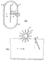
- the tank which is the preferred embodiment of this invention comprises a chamber 6, generally oval in plan, divided by a central wall 8 to provide a continuous flow path F, inlet and outlet pipes 10, 12 being provided in conventional manner.
- impeller means in the form of a rotor 14 on which paddles 16 are mounted.
- the paddles are arrayed generally helically in the longitudinal direction of the rotor.
- the rotor is typically rotated at about 70 r.p.m., the paddles driving the liquor around the flow path in the direction indicated, and to induce bubbles of air into the liquor, to assist in the aerobic digestion of the liquor.
- baffle 18 Located downstream of the impeller and extending across the flow path is deflector means afforded by a baffle 18.
- the baffle member 18 extends downwardly into the liquor from a position slightly above the surface thereof, conveniently extending about one quarter - one third of the way into the liquor.
- the extent to which the baffle element extends above the surface is preferably sufficient to ensure no significant flow of liquor, under the action of the impeller, over the tap of the baffle element.
- the baffle is inclined at an angle a to the vertical, typically between 30 0 - 60 0 , (the direction of inclination being away from the impeller in the downward direction) such that liquor impelled in the direction F by the impeller on striking of the baffle member 18, is forced downwardly, towards the bottom of the tank, carrying downwardly the bubbles of air produced by the impeller, and increasing the rate at which the oxygen is dissolved by the liquor.
- an impeller is used having a diameter of 1.0 meter, and the baffle element is positioned approximately 7 meters downstream of the rotor at an angle of 45 0 , extending from 500 mm above the liquor level to I meter below the liquor level.
Landscapes
- Life Sciences & Earth Sciences (AREA)
- Biodiversity & Conservation Biology (AREA)
- Microbiology (AREA)
- Hydrology & Water Resources (AREA)
- Engineering & Computer Science (AREA)
- Environmental & Geological Engineering (AREA)
- Water Supply & Treatment (AREA)
- Chemical & Material Sciences (AREA)
- Organic Chemistry (AREA)
- Mixers Of The Rotary Stirring Type (AREA)
- Aeration Devices For Treatment Of Activated Polluted Sludge (AREA)
Applications Claiming Priority (2)
| Application Number | Priority Date | Filing Date | Title |
|---|---|---|---|
| GB8415415 | 1984-06-16 | ||
| GB8415415A GB8415415D0 (en) | 1984-06-16 | 1984-06-16 | Aeration plant |
Publications (2)
| Publication Number | Publication Date |
|---|---|
| EP0165552A2 true EP0165552A2 (fr) | 1985-12-27 |
| EP0165552A3 EP0165552A3 (fr) | 1987-06-16 |
Family
ID=10562556
Family Applications (1)
| Application Number | Title | Priority Date | Filing Date |
|---|---|---|---|
| EP19850107260 Withdrawn EP0165552A3 (fr) | 1984-06-16 | 1985-06-12 | Installation d'aération |
Country Status (3)
| Country | Link |
|---|---|
| EP (1) | EP0165552A3 (fr) |
| GB (2) | GB8415415D0 (fr) |
| ZA (1) | ZA854511B (fr) |
Cited By (1)
| Publication number | Priority date | Publication date | Assignee | Title |
|---|---|---|---|---|
| CN116240848A (zh) * | 2023-03-14 | 2023-06-09 | 天津大学 | 扰冰设备及基于扰冰设备的扰冰方法 |
Families Citing this family (2)
| Publication number | Priority date | Publication date | Assignee | Title |
|---|---|---|---|---|
| US5611926A (en) * | 1995-01-13 | 1997-03-18 | Nishida; Tetsuo | Water treatment device |
| DE20005298U1 (de) | 2000-03-21 | 2000-08-10 | Westermann GmbH & Co. KG, 49838 Lengerich | Kläranlage und darin verwendbare Vorrichtung zum Bewegen einer Flüssigkeitsoberfläche |
Family Cites Families (8)
| Publication number | Priority date | Publication date | Assignee | Title |
|---|---|---|---|---|
| DE1158009B (de) * | 1957-12-21 | 1963-11-21 | Passavant Werke | Verfahren und Belueftungsbecken zum Belueften von Fluessigkeiten, insbesondere von Abwasser |
| US3561738A (en) * | 1969-02-10 | 1971-02-09 | Owens Illinois Inc | Aeration apparatus |
| DE2043148B2 (de) * | 1970-08-31 | 1973-11-22 | Passavant - Werke Michelbacher Huette, 6209 Aarbergen | Vorrichtung zur Abwasserreinigung nach dem Belebtschlammverfahren |
| DE2412543C2 (de) * | 1974-03-15 | 1977-06-23 | Schreiber, August, Dr.-Ing., 3001 Vinnhorst | Vorrichtung zur biologischen Reinigung von Abwasser mit einem langgestreckten Umlaufbecken. |
| GB1457721A (en) * | 1975-01-21 | 1976-12-08 | Passavant Werke | Apparatus for the surface aeration of waste water |
| GB2011795B (en) * | 1978-01-06 | 1982-07-21 | Hartley Simon Ltd | Aeration of liquids |
| GB1594767A (en) * | 1978-05-16 | 1981-08-05 | Mahon & Mcphillips Ltd | Purification of sewage |
| EP0065047A1 (fr) * | 1981-05-19 | 1982-11-24 | Paul Ingolf Rongved | Système de traitement d'eau usée utilisant des moyens d'aération et de circulation |
-
1984
- 1984-06-16 GB GB8415415A patent/GB8415415D0/en active Pending
-
1985
- 1985-06-12 GB GB08514857A patent/GB2160192B/en not_active Expired
- 1985-06-12 EP EP19850107260 patent/EP0165552A3/fr not_active Withdrawn
- 1985-06-14 ZA ZA854511A patent/ZA854511B/xx unknown
Cited By (1)
| Publication number | Priority date | Publication date | Assignee | Title |
|---|---|---|---|---|
| CN116240848A (zh) * | 2023-03-14 | 2023-06-09 | 天津大学 | 扰冰设备及基于扰冰设备的扰冰方法 |
Also Published As
| Publication number | Publication date |
|---|---|
| GB8415415D0 (en) | 1984-07-18 |
| GB2160192B (en) | 1989-02-01 |
| GB8514857D0 (en) | 1985-07-17 |
| ZA854511B (en) | 1986-02-26 |
| EP0165552A3 (fr) | 1987-06-16 |
| GB2160192A (en) | 1985-12-18 |
Similar Documents
| Publication | Publication Date | Title |
|---|---|---|
| US3840216A (en) | Vacuum aeration of liquid waste effluent | |
| CA1124415A (fr) | Appareil melangeur de fluides | |
| US5045202A (en) | Centrifugal oxygenator for treatment of waste water and system | |
| USRE29781E (en) | High oxygen utilization in BOD-containing water treatment | |
| CA1038090A (fr) | Reacteur de traitement biologique de l'eau | |
| US3510110A (en) | Sewage purification | |
| US4009100A (en) | Method of treating waste water with jet nozzles | |
| JP2010535627A (ja) | 曝気のための方法及び装置 | |
| US4240905A (en) | High solids mixture aeration method | |
| US4869818A (en) | Orbital wastewater treatment system with combined surface aerator and submerged impeller | |
| US5772886A (en) | Aquaculture process | |
| EP0165552A2 (fr) | Installation d'aération | |
| US4166790A (en) | Single stage process for continuous introduction of oxygen-containing gases into effluent containing activated sludge | |
| US2597802A (en) | Apparatus for treating liquid sewage and the like | |
| US3207313A (en) | Apparatus for aeration of waste products | |
| EP0606432A1 (fr) | Reacteur. | |
| US2969225A (en) | Detention and mixing apparatus for treating waste liquids | |
| RU2114793C1 (ru) | Установка биологической очистки сточных вод | |
| CA3157698A1 (fr) | Autoclave et procede d'oxydation sous pression | |
| EP0027911B1 (fr) | Appareil pour mettre en contact un liquide avec un gaz | |
| US4202762A (en) | Process and device for the aeration of waste water | |
| KR20040092843A (ko) | 기체의 용해 및 혼합을 이용한 오폐수 처리장치 | |
| US4734197A (en) | Jet aerator header assemblies and methods for use thereof in total, partial, and non-barriered oxidation ditches | |
| IL45829A (en) | Method and apparatus for oxygenating wastewater | |
| EP0902761A1 (fr) | Station d'epuration pour traitement des eaux |
Legal Events
| Date | Code | Title | Description |
|---|---|---|---|
| PUAI | Public reference made under article 153(3) epc to a published international application that has entered the european phase |
Free format text: ORIGINAL CODE: 0009012 |
|
| AK | Designated contracting states |
Designated state(s): AT DE FR IT NL SE |
|
| PUAL | Search report despatched |
Free format text: ORIGINAL CODE: 0009013 |
|
| AK | Designated contracting states |
Kind code of ref document: A3 Designated state(s): AT DE FR IT NL SE |
|
| STAA | Information on the status of an ep patent application or granted ep patent |
Free format text: STATUS: THE APPLICATION IS DEEMED TO BE WITHDRAWN |
|
| 18D | Application deemed to be withdrawn |
Effective date: 19870617 |
|
| RIN1 | Information on inventor provided before grant (corrected) |
Inventor name: HAGAN, JAMES GERALD Inventor name: DENTON, RODNEY STUART |